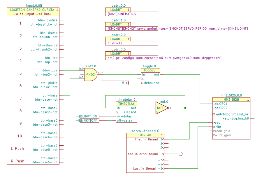
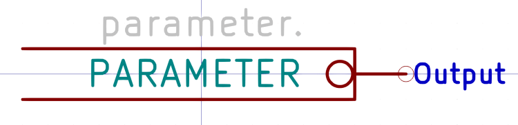
Kicad PARAMETER symbols (center, left of the upper TOGGLE) provide the value for HAL setp commands:
Which becomes this line in the HAL file:
setp toggle.0.debounce 5 # parameter.0
Parameter pins use the Inverted graphic style decorating them with a small circle to distinguish parameters from ordinary data pins, but the data value is not inverted. Parameter components can also connect to ordinary HAL input pins without the Inverted style.
PARAMETER symbols have an invisible reference value (parameter.0 in the example) that you don’t care about:
Edit the value inside the symbol to whatever you need.
Kicad CONSTANT symbols (lower center, left of the TIMEDELAY symbol) generate HAL CONSTANT modules, set their values, and connect them to a thread. The resulting HAL commands look like this:
addf constant.0		servo-thread
addf constant.1		servo-thread

… snippage …

setp constant.0.value [BLINKY]ON
setp constant.1.value [BLINKY]OFF

… snippage …

net N_001 <= constant.1.out => timedelay.0.off-delay
net N_002 <= constant.0.out => timedelay.0.on-delay
The thread connections works the same way as for other HAL components with the automagic net connection to “_”:
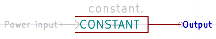
The (invisible) + in the middle tells Kicad-to-HAL to put the total number of CONSTANT components into the addf command.
As with Parameters, edit the CONSTANT inside the symbol as needed.
Both Parameters and Constants can use text values defined in the INI file:
[BLINKY]
ON = 0.2
OFF = 2.0
Both Parameters and Constants can connect to nets going to multiple input pins, but it’s probably not worth cluttering a schematic with off-page connectors just to reuse a single instance. When you copy-n-paste an otherwise identical symbol somewhere else, it will get a different reference number and generate additional HAL commands, which may offend your sense of neatness.

Comments
One response to “Kicad-to-HAL: Parameters and Constants”
[…] Parameters and constants: https://softsolder.com/2021/03/30/kicad-to-hal-parameters-and-constants/ […]