Ed Nisley's Blog: Shop notes, electronics, firmware, machinery, 3D printing, laser cuttery, and curiosities. Contents: 100% human thinking, 0% AI slop.
It’s one of the few Underwriter’s Knots I’ve ever seen in the wild. Many recent (i.e., built in the last half-century) lamps pass the cords through a plastic clamp or depend on simple bushings, with some just ignoring the problem.
This anonymous lamp sports the usual Made in China sticker, but also features a genuine-looking UL sticker complete with elaborate holograms, so it may well have been sold by a reputable company. IIRC, it came from a trash can in a Vassar College hallway, back when in-person meetings were a thing; perhaps Vassar required known-good electrical hardware.
A new floor lamp similar to the one I adjusted to suit my chair appeared next to Mary’s chair. It was, as I expected, much too tall, but shortening it required just removing one of the vertical tube sections (exactly one foot long!), as Mary was content with the flexy arm’s reach. Perhaps as a nod to the current chip shortage, this version of the lamp has a control consisting of a mechanical knob in a lump just under the flexy arm: push to turn on, rotate for intensity, tap for color, push-and-hold for off. This is much more usable than the finicky proximity pads on my lamp (and the slightly more expensive version of this one), which is why I picked it.
Because the coaxial power connector doesn’t fit through the bushing in the base of the vertical tubes and didn’t have a connector at the control lump, I had to dismantle the lump to disconnect the power cable to remove the pipe section, an operation deep in warranty violation territory.
So, we begin.
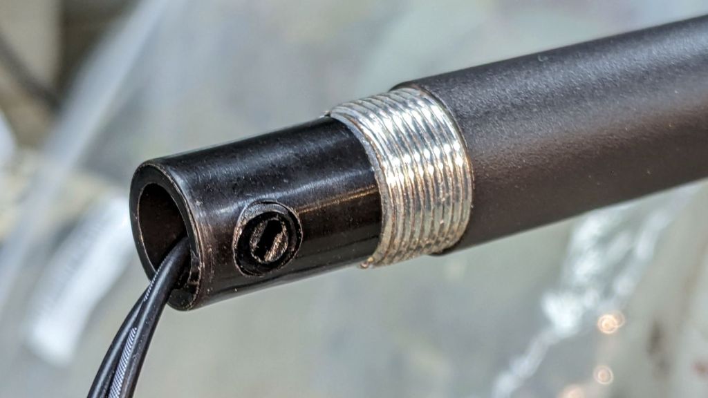
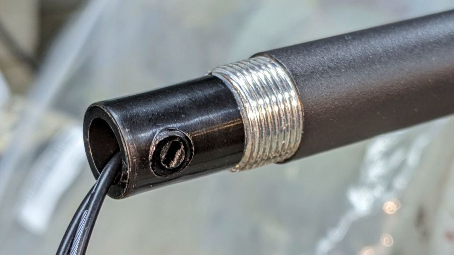
Loosen the screw clamping the power cord to the tube just below the control lump:
LED Floor Lamp – DC wire clamp
Remove the two screws holding the control lump together:
LED Floor Lamp – control case
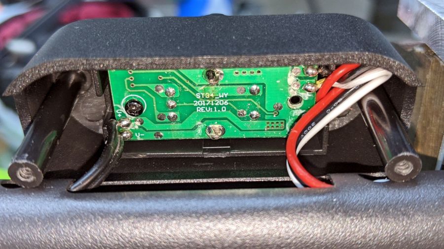
Pull the front of the lump off the tube and peel off a protective foam sheet to expose the circuitry:
LED Floor Lamp – PCB silkscreen
Power comes from a 12 VDC 400 mA wall wart, so note the wire markings:
LED Floor Lamp – DC wire marking
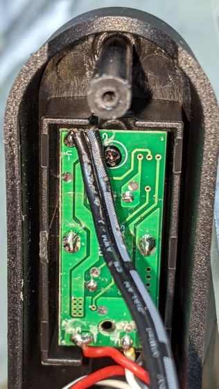
In this case, the marked wire (with the dashed lines) is the positive conductor:
LED Floor Lamp – DC polarity PCB marking
Unsolder the cable and pull it out of the entire collection of tubing. The topmost section has two inner threads, so remove one of the other sections (with inner and outer threads) and reassemble the rest. Poke the cable through the tubes, solder to PCB, tighten clamp screw, reassemble lump in reverse order, then declare victory:
LED Floor Lamp – shortened
The business end now hovers 39 inches (a neat 1 m) over the floor, just below her eye level, where it belongs.
An ancient Ottlite fluorescent floor lamp (one of a pair bought during a closeout sale at a minute fraction of their absurd sticker price) finally aged out. Pondering what to do with the carcass led to this discovery:
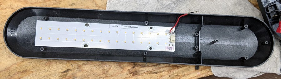
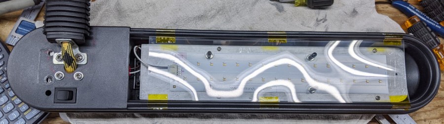
Ottlite conversion – LED panel fit check
Half of a Samsung (!) LED panel (presumably sheared by the surplus supplier) fit so perfectly in place of the fluorescent tube that I just had to make it happen.
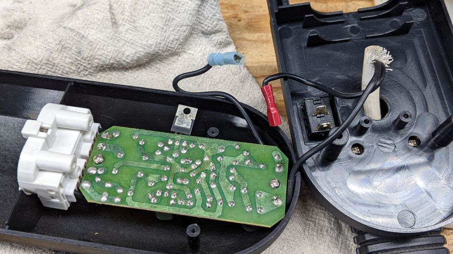
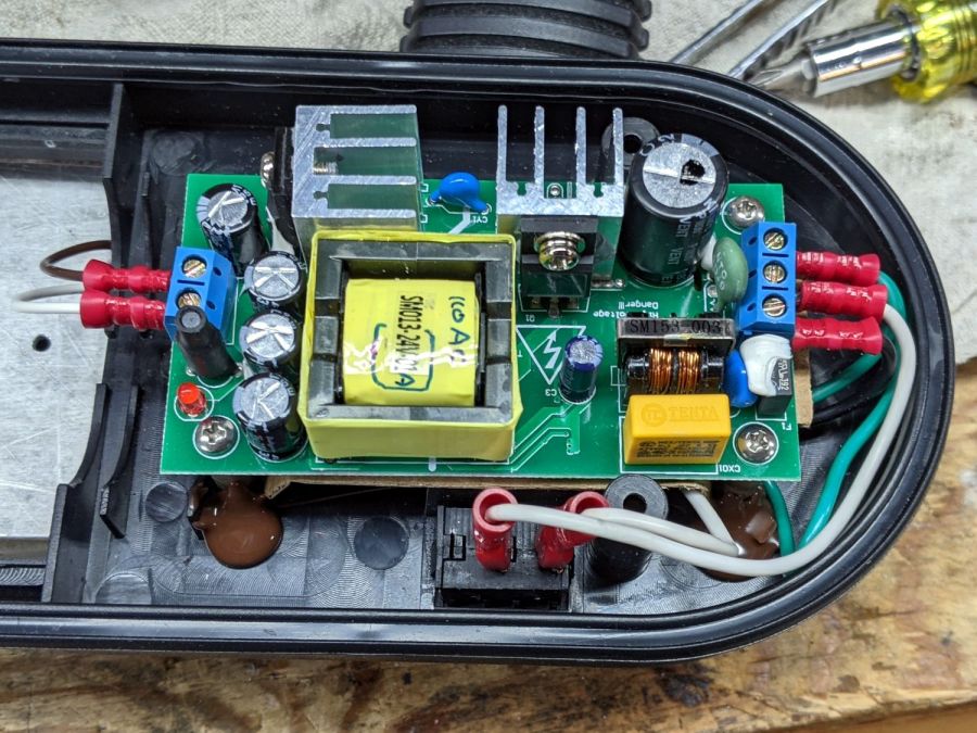
The original fluorescent ballast mounted in the smaller compartment:
Ottlite conversion – OEM fluorescent driver
I like the air-cooled triac sticking off the side of the PCB.
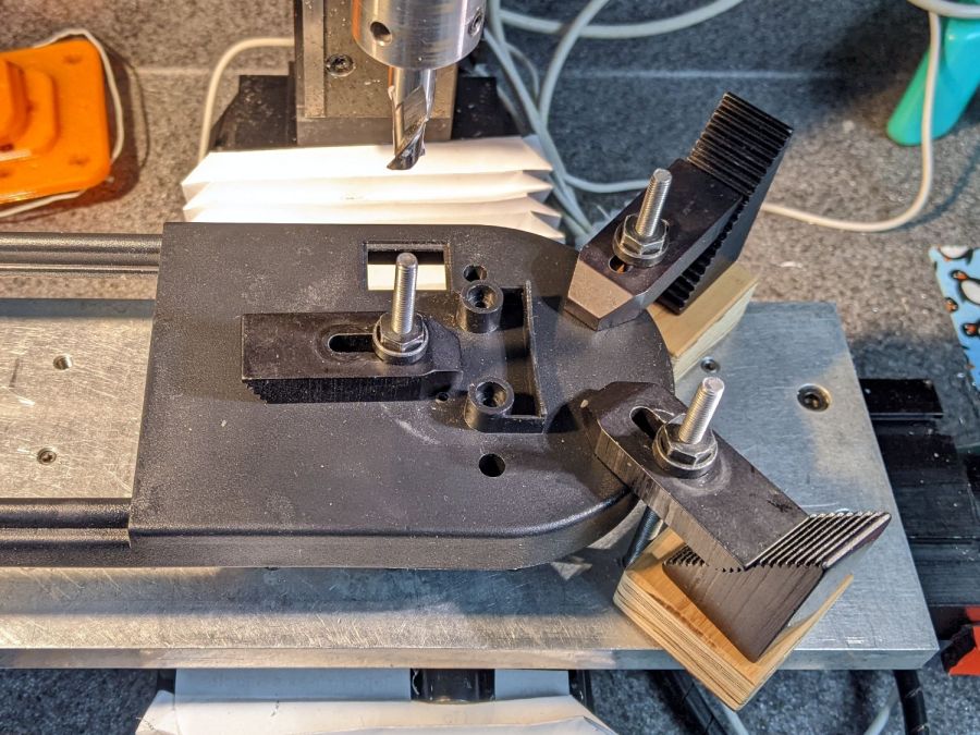
The lamp originally mounted parallel to the flex arm, but I wanted it at a right angle, so the molded bracket had to go:
Ottlite conversion – bracket milling setup
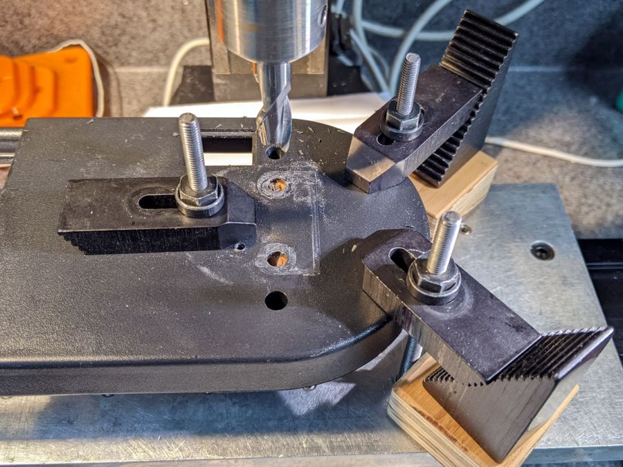
Which required a few minutes of manual jogging:
Ottlite conversion – bracket milled
Some coordinate drilling on the Sherline converted a rectangle of aluminum sheet into a backing plate inside the base (visible through the original holes) to spread the stress over a larger area:
Ottlite conversion – flex arm mount
The new 24 V 1 A power supply mounts pretty much where the OEM ballast came from, although I had to hack out the molded screw bosses and perch the PCB atop four aluminum standoffs anchored in globs of high-temperature hot-melt glue:
Ottlite conversion – power supply
You might think the white and black wires on the right are interchanged, because you’re not supposed to switch the neutral, but only if you also insist anybody cares about the colors of wires inside a molded cord. This one came from a nominally good-quality cord with an IEC connector now in the e-waste box: trust yet always always verify.
The LED panel sticks to the aluminum sheet with thermal tape and is clamped in place with a quartet of M2.5 standoffs:
Ottlite conversion – bottom view
I’ll eventually make a better cover than a strip of overhead projector film (remember overhead projectors?), as spattering the LEDs with cutting oil and random conductive swarf is Bad Practice™.
A little more cutting and drilling produced an angle bracket for the lathe backsplash panel:
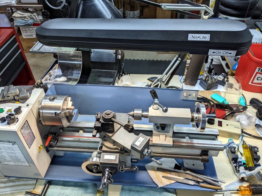
Ottlite conversion – installed
Thing looks like it grew there, doesn’t it?
The end of the backsplash might need a 3D printed bracket to stabilize its right-angle bends and prevent wobbulation, although I’ll wait until that becomes a real problem before solving it.
The top of that stylin’ lamp shade tapers along its length and, unfortunately, appears directly in front of the MPCNC bench across the basement (out of sight at the top) as I stand at the lathe. Having the shade not align exactly parallel to the bench is more annoying than it really should be; perhaps I can get used to it after spending more time at the lathe.
Harvesting a line cord for a widowmaker test setup revealed its inner secret:
Mystery not-copper wire – as found
The conductors are as thin as I’ve ever seen in an AC line cord, with 0.5 mm² = just under 20 AWG. The color code doesn’t match USA-ian standards, but neither does the labeling, so I’m not surprised.
If the individual strands seem unnaturally straight, they are, because they’re made of (presumably) copper plated on a (presumably) metallic core. Here’s what they look like after bending them sharply around my fingernail:
Mystery not-copper wire – bending
Wonderfully springy, utterly non-magnetic, and surprisingly durable.
Scraping the 0.02 mm strands with a sharp blade reveals a silvery interior, so it’s (presumably) not copper-coated plastic. Aluminum springs (ahem) to mind, but I’d expect tiny aluminum strands would snap (or at least deform) when bent and erode quickly when scraped.
Each wire measures about 1 Ω / m from the plug (a convenient 40 inch = 1 m away), which is the resistance you’d get from a single hair-fine 5 mil = 0.13 mm strand of 35 AWG solid copper. An 18 AWG aluminum wire would have the same resistance as a 20 AWG copper wire, both of which should be 32 mΩ / m: a factor of 30 less than this crap.
A hank of the wire goes into the Box o’ Springs, in the event I ever need a tiny straight spring rod; you definitely can’t wind this stuff into a coil! It might be fine enough for a crosshair / reticle, at least for crude optics.
Having put the Tek AM503 with the 4 MHz oscillation (B075593) on the shelf pending arrival of what might be the world’s last remaining NOS 2625 op amp in the “screened and tested” 156-0317-03 grade, I figured I might as well go through the adjustment procedure on one of the bench units (B064098) to reset the gain and reduce the peaky leading edges (green trace):
Tek AM503 – B031510 B064098 – 10mA-div
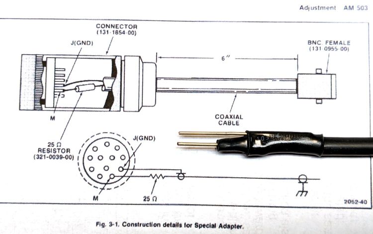
I conjured a low-budget Special Adapter to feed signals into the front-panel connector:
Tektronix AM503 Special Adapter
I also used a somewhat smaller resistor in place of the required 3 Ω 3 W wire-wound unit:
Tek AM503 – 3 ohm test resistor
It need only soak up a few seconds of the degaussing signal and never even got warm, so it’s all good.
To my surprise, the square-wave output of the JDS6600 Function Generator meets the 10 ns risetime requirement:
JDS6600 Fn Gen – risetime 50 ohm
Perhaps half an hour of adapter shuffling and trimmer twiddling later, the AM503 output looked better:
Tek AM503 – compensation adj
The (purple) input comes from the function generator output through a BNC tee and an unterminated foot of coax, so the leading edge ringing is perfectly normal.
With the scope input now providing the 50 Ω termination and the Hall probe clamped around one wire of a clip-to-clip pair of BNC-to-alligator-clip adapters, we’re still not talking RF-grade interconnection quality:
Tek AM503 – 1 MHz square
Even through it’s not factory spec, the output tracks the input well enough for my simple needs.
One of the Tekronix AM503 current probe amplifiers arrived without the panel bushing for the Balance trim pot. Back in the day, you could presumably order part number 350-0301-02 and have it delivered (most likely) by your local Tek representative:
Balance pot panel bushing – Tek part listing
Those days are over.
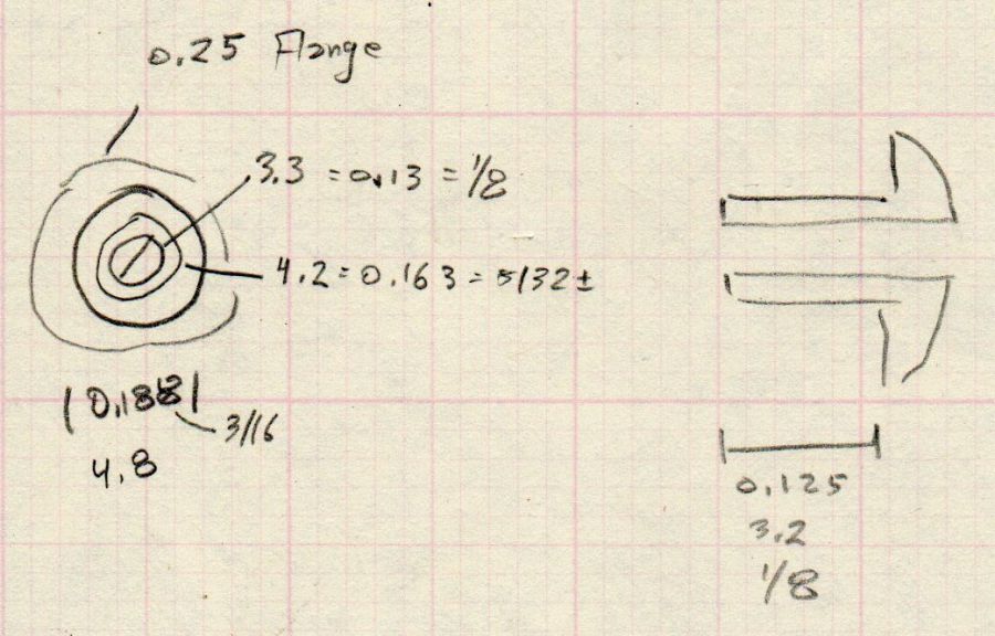
A few minutes produced a doodle with pretty-close measurements:
Balance pot panel bushing – dimension doodle
The as-built bushing turned out just a smidge too long, so make yours a scant eighth of an inch. Maybe the Tek dimension is the overall length?
An SLA resin printer might crank out such a thing, but it’s well below the looks-good / fits-well resolution limit of an ordinary fused-filament printer.
Applying the mini-lathe to a 1/4 inch white acrylic rod produced a reasonable facsimile:
Tek AM503 Balance pot bushing – front
The side view:
Tek AM503 Balance pot bushing – side
Acrylic is definitely the wrong material for the job, but it came readily to hand while pondering the Shelf o’ Rods. Acetal would be better, as you could easily trim off the aforementioned excess length with a knife.
All’s well that ends well:
Tek AM503 Balance pot bushing – installed
A dab of white acrylic adhesive around the raw opening holds the bushing in place and it looks good enough to me.
The motivation for this boils down to having the bushing center the pot twiddler required to set the balance, which I must do every time I fire up the amps, even after waiting for the half-hour required to stabilize them at their operating temperature.