My friends in Raleigh sent a small box with the various tools I made, along with the scorched Bafang battery charge port. As it turned out, none of the tools were useful and the real fix required opening the battery cover enough to remove and replace the charge connector.
A view looking straight into the connector, with the side contact on the top of the image:
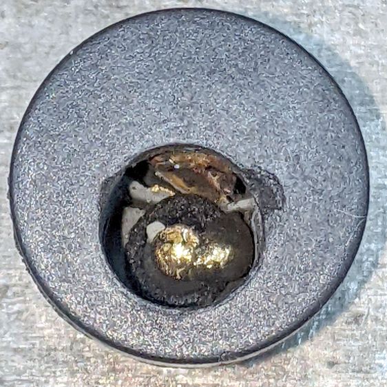
Gutting the connector shows why my homebrew shell drill wasn’t going to work:

There’s not much left of the central pin: the nugget hanging on its side is much larger than I expected. Most of the pin melted into that nugget, with a bonus droplet on the near side.
The rectangular chunk (upper right) is the switch terminal, with the tab from the side contact (on the right) welded to it.
Fortunately, none of the mayhem (including a few small sparks during the connector replacement) damaged the battery management circuitry or triggered a shutdown, so the reset tool wasn’t needed.
It’ll make a great 3D printing show-n-tell exhibit, in the unlikely event I ever do an in-person talk …