Having put the Tek AM503 with the 4 MHz oscillation (B075593) on the shelf pending arrival of what might be the world’s last remaining NOS 2625 op amp in the “screened and tested” 156-0317-03 grade, I figured I might as well go through the adjustment procedure on one of the bench units (B064098) to reset the gain and reduce the peaky leading edges (green trace):

I conjured a low-budget Special Adapter to feed signals into the front-panel connector:
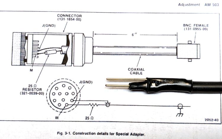
I also used a somewhat smaller resistor in place of the required 3 Ω 3 W wire-wound unit:

It need only soak up a few seconds of the degaussing signal and never even got warm, so it’s all good.
To my surprise, the square-wave output of the JDS6600 Function Generator meets the 10 ns risetime requirement:

Perhaps half an hour of adapter shuffling and trimmer twiddling later, the AM503 output looked better:

The (purple) input comes from the function generator output through a BNC tee and an unterminated foot of coax, so the leading edge ringing is perfectly normal.
With the scope input now providing the 50 Ω termination and the Hall probe clamped around one wire of a clip-to-clip pair of BNC-to-alligator-clip adapters, we’re still not talking RF-grade interconnection quality:

Even through it’s not factory spec, the output tracks the input well enough for my simple needs.
Good old Tek instruments: gotta love ’em!

Comments
4 responses to “Tektronix AM503: Adjustment”
Stupid question, but where does the 25ns delay come from?
AFAICT, that’s the delay from the Hall sensor through all the analog circuitry to the output.
A quick look through the specs gives radio silence on the delay, but does remind me the bandwidth is 50 MHz with the P6302 probe; the 29 ns risetime suggests 17-ish MHz, but from an input that isn’t a good step function.
The Hall sensor isn’t in circuit during this, right, you’re injecting a signal with your Special Adaptor? 25ns latency seems like an awfully long time to me! If you were running at the 50MHz bandwidth limit you’d be almost an entire cycle out of phase.
Except for the last picture, the signal comes directly from the signal generator into the connector.
As long as the amp’s delay is constant (*), I think it’s largely irrelevant to the results, unless you’re interested in real vs. reactive power at absurdly high frequencies, in which case the phase difference matters a lot.
(*) I vaguely recall this requires linear phase response, although I have no idea whether the AM503 behaves like that … or even how I’d measure it.