Ed Nisley's Blog: Shop notes, electronics, firmware, machinery, 3D printing, laser cuttery, and curiosities. Contents: 100% human thinking, 0% AI slop.
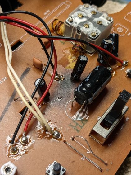
A power failure apparently pushed the ancient RCA alarm clock over the edge into a mode where it ignored its pushbuttons and displayed a time based on a hitherto unknown exoplanet. Popping the case revealed it’s been simmering in its own juices for quite a while:
RCA Alarm Clock – PCB overheat
There’s nothing obviously scorched on the underside of the PCB, although a large SMD resistor might be the source of the problem.
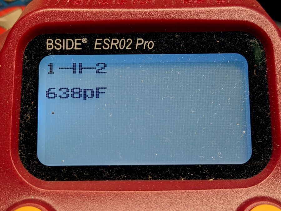
Having been around this block a few times, I unsoldered that big electrolytic cap with its guts protruding from the overwrap:
RCA Alarm Clock – failed cap value
Nope, that’s not really an electrolytic cap any more.
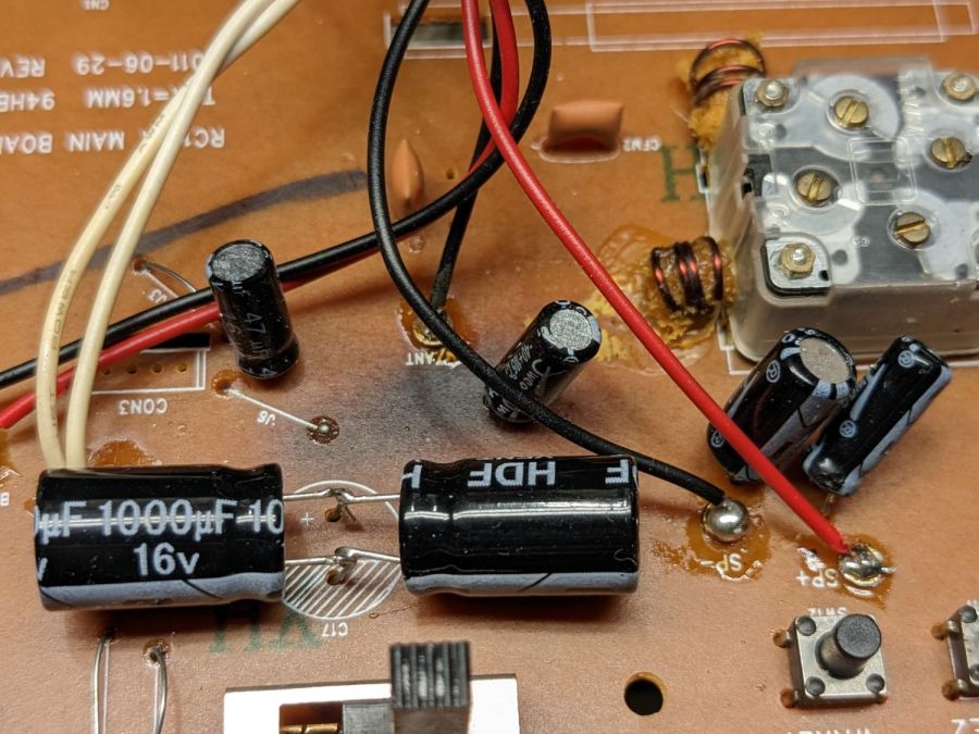
Lacking a 2200 µF cap of suitable voltage rating, but knowing cap tolerances allow for considerable windage, this worked out well enough:
RCA Alarm Clock – replacement caps
Two smaller caps measuring on the low side of OK now reside in the e-waste box.
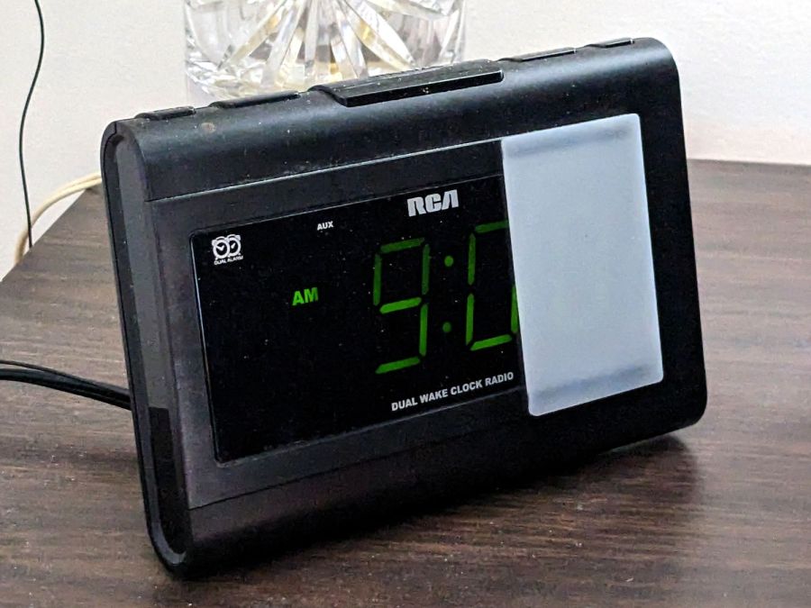
The white diffuser over the last digit improves it in ways I do not profess to understand, but am pleased to implement:
RCA Alarm Clock – in place
It’s held in place by two strips of LSE tape to see how it reacts to prolonged shear force, no matter how gentle.
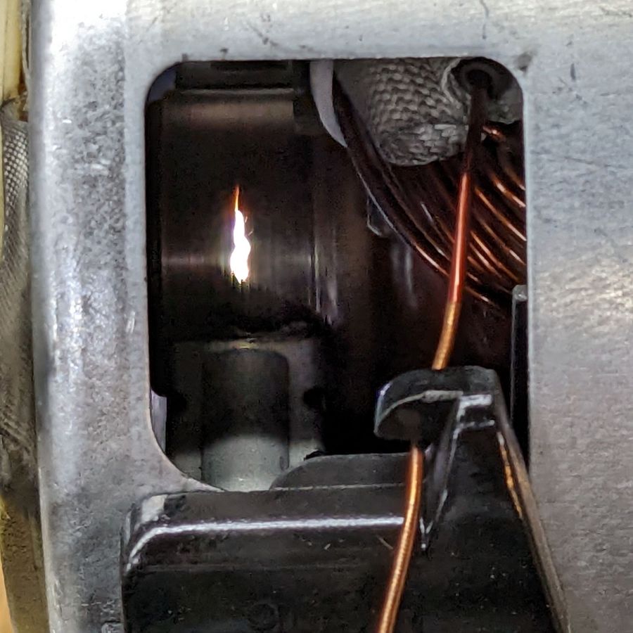
Apparently igniters last about eight years, regardless of provenance, because the igniter just failed, with the usual symptoms of low current draw (about 2 A), failed ignition, and a faint smell of propane (well, mercaptan) before the safety valve kicked in:
Oven igniter – location
The new igniter, another low-buck Amazon offering, came with half a green plastic connector block that mated neatly with the existing half under the oven. Unfortunately, the new wires had female pins crimped on their ends, rather than the male pins required by the existing connector and the ceramic wire nuts I’d used to join the previous igniter to the OEM connector were non-removable.
So I trimmed the old wires to a usable length and applied the new ceramic wire nuts to the stubs:
Oven igniter – connector rewiring
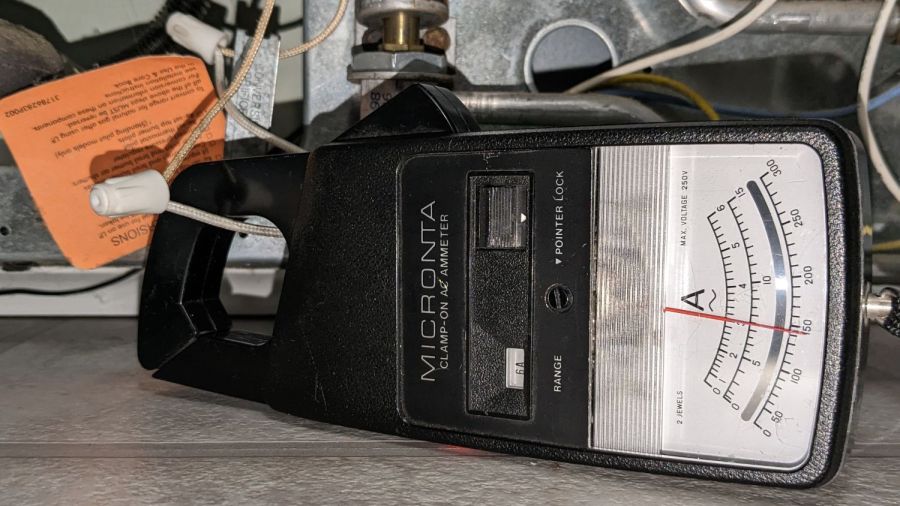
Also as before, the new igniter measures 3 A, definitely below the low end of the valve’s 3.3 to 3.6 A range:
Oven igniter – current test
If this one lasts eight years, I won’t be the guy replacing it …
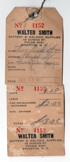
I know it’s still good, because the label has its 4 lb 7 oz refilled gross weight stamped into it, which is exactly what it weighs today.
Walter Smith Welding Supplies may still be in business, perhaps in Poughkeepsie, but their former 18 Downs St location in Kingston has become Noble Gas Solutions:
Noble Gas Solutions – 18 Downs St Kingston – 2019
Back then, you could call Smith Welding at a four digit phone number in Kingston: 5061. Nowadays, you must call Noble Gas with three more digits: 338-5061. As Charles Stross observed, something like 70% of the future is already in place, because infrastructure is so tenacious.
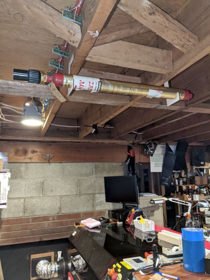
Heck, just look at that Quonset hut!
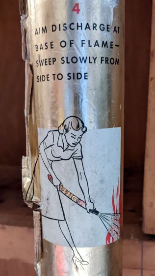
Keep calm and extinguish on:
Fyre Freez extinguisher – step 4
Two thoughts spring to mind:
Most kitchen fires start waist-high (it’s the late 1950s: where else would she be?)
She’s gonna lose skin on that metal tank
Seems to me a Fyre Freez will get cold enough to freeze skin while discharging, but I admit to not having actually tried it.
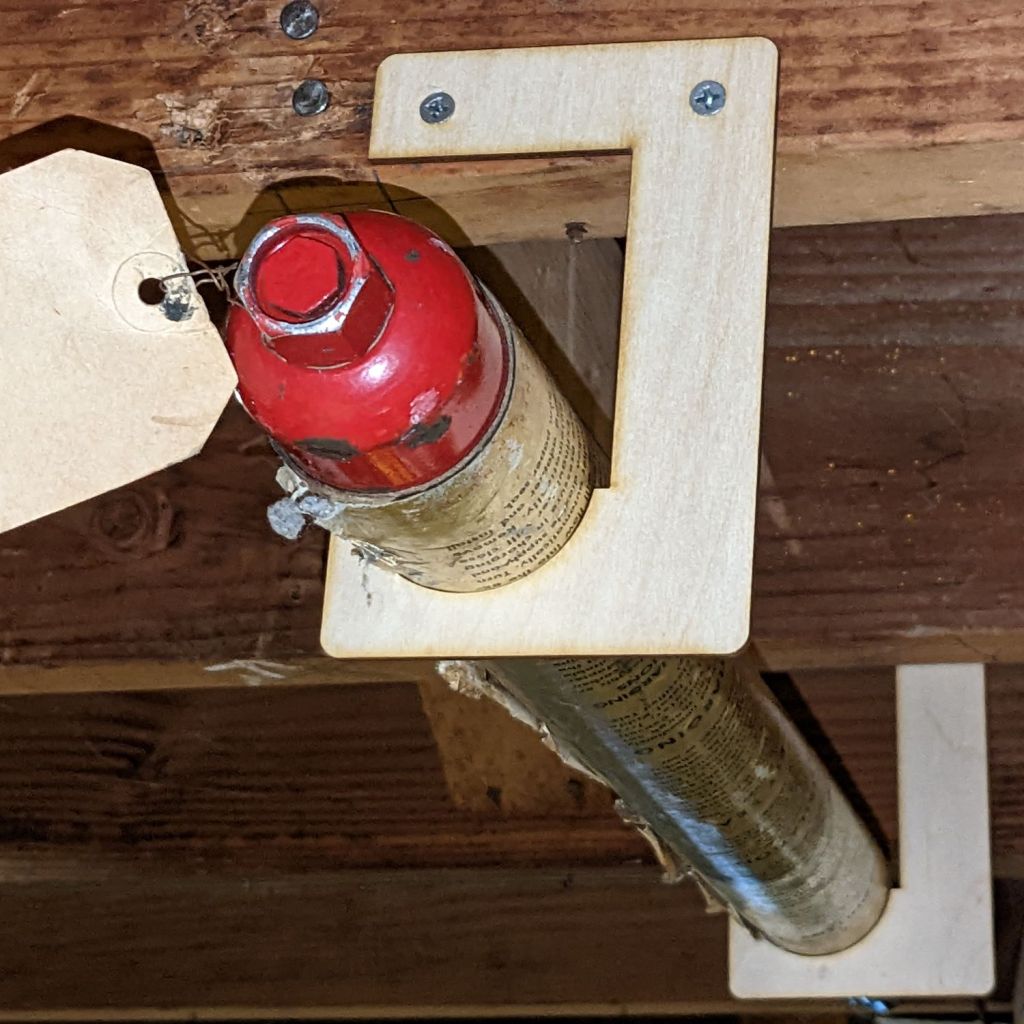
Anyhow, given the overall basement decor, the brackets have the right general style:
Fyre Freez extinguisher – bracket detail
Here’s hoping its future will be as dull as its past …
It’s easy to find the two front screws holding the top in place, although you’ll need either a bendy or offset screwdriver to remove them:
Sears Progressive Vacuum – front case screws
Pull up hard on the cord retraction plunger to remove it, revealing the two rear screws:
Sears Progressive Vacuum – rear case screws
Extract the wires and motor control PCB from their niches:
Sears Progressive Vacuum – motor assembly overview
Prying the latch in the middle of the rear panel (over on the right) releases the motor assembly, which you can then wiggle-n-jiggle upward and out:
Sears Progressive Vacuum – extracting motor assembly
Disconnect the wires, peel off various foam bits, and extract the motor from its carapace. Measure the blower diameter and cut a suitable plywood clamp for the bench vise:
Sears Progressive Vacuum – custom motor clamp
I loves me some good laser cutter action, even when the plywood crate the laser came in doesn’t have much to recommend it:
Sears Progressive Vacuum – failed plywood clamp
I vaguely recall reading the purple tinge comes from the bromine vapor used to dis-insect the wood during manufacturing, before shipping it halfway around the planet.
One area of the commutator looks like it’s in bad shape:
Sears Progressive Vacuum – as-found commutator
Clean the commutator bars in the desperate hope it’s just random crud, even though that seems unlikely, then connect a widowmaker cord to the motor terminals:
Sears Progressive Vacuum – widowmaker line cord
Use a Variac to spin the motor at a (relatively) low speed while watching the brushes and commutator:
Sears Progressive Vacuum – commutator sparking
Now, that is not a nominal outcome.
The cleaned commutator again shows signs of distress:
Sears Progressive Vacuum – scarred commutator
Indeed, measuring the resistance across the line cord terminals shows a shorted winding: 0.0 Ω with the brushes aligned on the bars just antispinward of the scars.
So the motor is definitely, irretrievably dead.
Extracting the brushes shows the arcs have eroded their spinward edges:
Sears Progressive Vacuum – eroded motor brushes
The dark smudge on the windings seems due to internal problems, rather than just the arcs, because the wiring crossing between the commutator and the smudge remains clean:
Sears Progressive Vacuum – charred motor windings
One can buy a used motor assembly on eBay for about $40, with no assurance it doesn’t also have a shorted winding.
The Hakko FX-888 soldering iron perched on the corner of my bench has a little red LED that lights up when it’s heating and goes off when it’s not. Unfortunately, while shutting down after fixing something, I sometimes glance at the thing while the LED is off, whereupon it will patiently keep the iron hot, sometimes for days, until I return.
A recent Squidwrench session gave me the opportunity to yoink that nuisance off the to-do pile where it has been pending since about ten minutes after I unboxed the iron a decade ago.
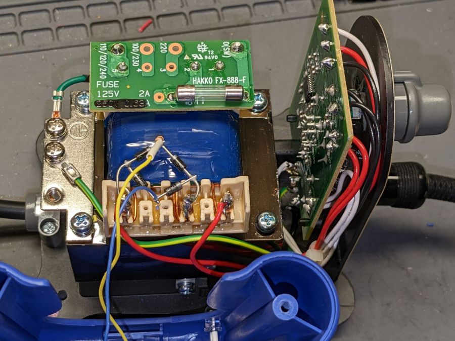
Some concerted rummaging failed to turn up the stash of bridge rectifiers, so I air-wired one from a quartet of discrete diodes:
Hakko 888 Soldering Iron pilot – bridge rectifier
Remember: the bigger the blob, the better the job.
For the record, the transformer produces 28 VAC, with the center tap 26 VAC from the left end and 2 VAC from the right end.
A 10 kΩ resistor stands upright at the far corner of the bridge, limiting the LED current to a few milliamps and making it bright enough for the purpose.
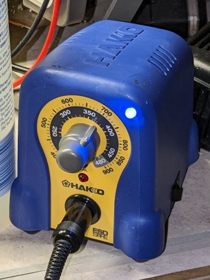
The front of the case has plenty of vacant space in its upper corners, so I drilled a hole and poked a blue LED:
Hakko 888 Soldering Iron pilot – heating
That’s shown with the iron heating.
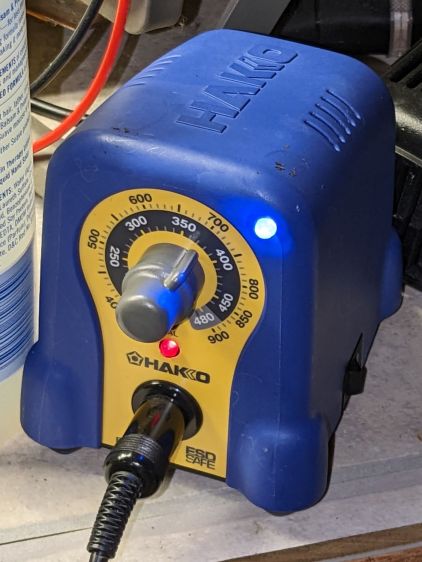
Here’s an action shot with the temperature at the setpoint:
Hakko 888 Soldering Iron pilot – stable
Nowadays all soldering irons have digital readouts with no need for a pilot light.
Of course, two days later I found the bridge rectifier stash, but there’s no point in opening the patient again.
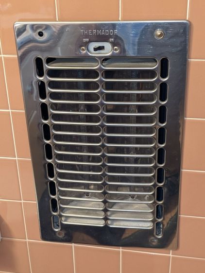
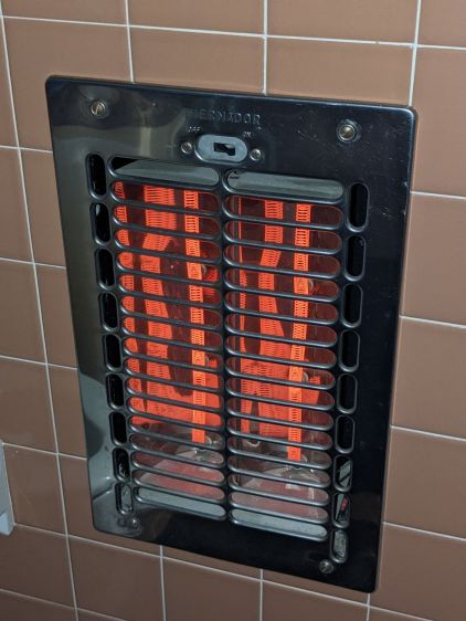
Our house dates back to 1955 and features several fancy items not found in contemporary dwellings. Take, for example, the Thermador in-wall heater in the front bathroom:
Thermador In-Wall Heater
It has a finger-friendly design apparently intended to admit a small finger through the grille, where it can easily contact the resistance heating coil, so while we were moving in I snapped a GFI circuit breaker into that slot in the breaker panel. We advised our (very young) Larval Engineer of the hazard and had no further problem; as far as I know, that breaker never tripped and no fingers were damaged.
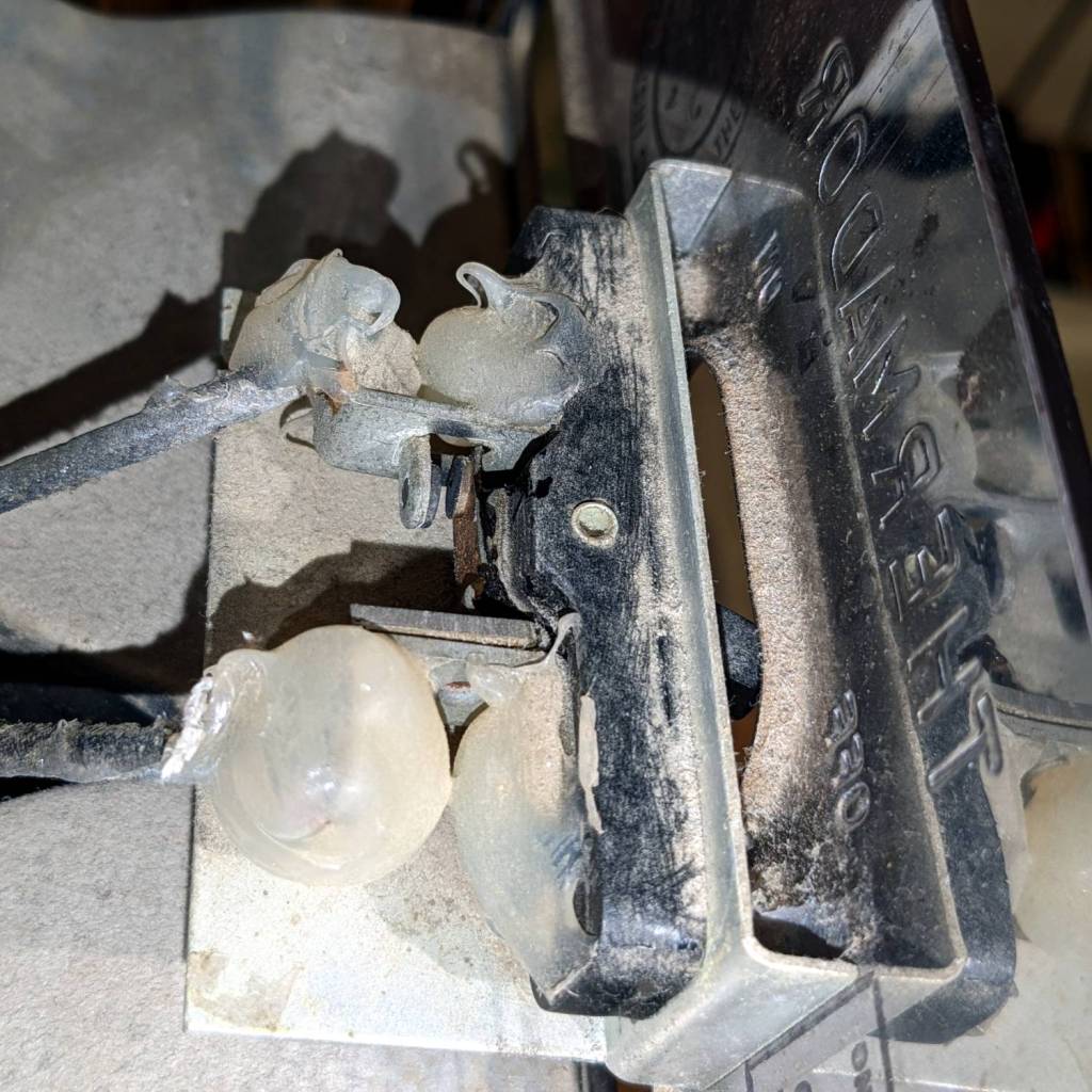
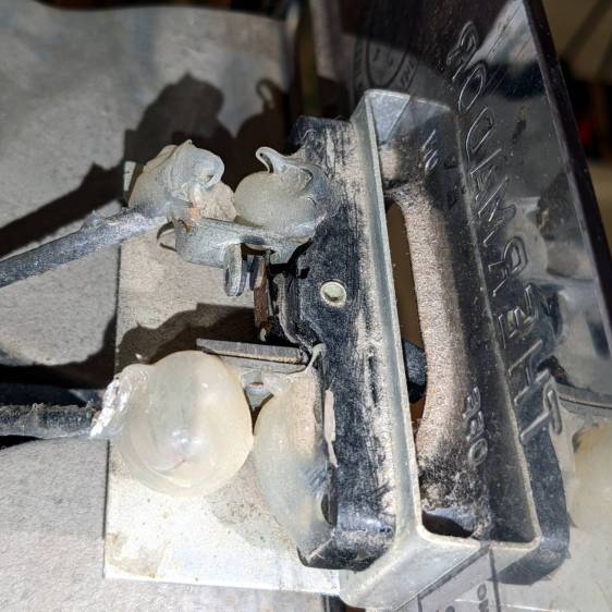
Back then, while adding that breaker and cleaning the first half-century of fuzz out of the thing, I evidently blobbed silicone rubber on the screw terminals of the switch:
Thermador In-Wall Heater – switch contacts
They don’t make switches like that any more.
For reasons not relevant here, we’ll be using it for the first time since we moved in, so I spent a while cleaning / blowing / brushing another two decades of fuzz out of it.
Minus the fuzz, the heater no longer smells like a house on fire:
The usual measurements of voltages and currents assume a constant load impedance, where the power varies with the square of the measured value. In this case, the laser tube is most definitely not a constant resistance, because it operates at an essentially constant voltage around 12 kV after lighting up at maybe twice that voltage. As a result, the power varies linearly with the measured voltages and currents, so the usual Bode plot “20 dB per decade” single-pole filter slope does not apply.
Because the laser tube power varies roughly with the current, I’ve been using the current as a proxy for the power, so the half-power points are where the current is half its value at low frequencies.
The controller’s analog voltage output is linearly related to the tube current and power, so the same reasoning applies.
That reasoning is obviously debatable …
Anyhow, it seems the PWM digital output is the primary signal source, with the L-AN analog output filtered from it. If you had a use for the analog voltage that didn’t involve sending it through a second low-pass filter, it might come in handy, but that’s not the case with the laser’s HV power supply.
Looking across the graph at the tube current’s half-power level of 12-ish mA shows 150 Hz for the L-AN output and 250 Hz for the PWM output. That’s roughly what I had guesstimated from the raw measurements, but it’s nice to see those lines in those spots.
In practical terms, grayscale engraving will operate inside an upper frequency limit around 200 Hz. Engraving a square wave pattern similar to the risetime target requires a bandwidth perhaps three times the base frequency for reasonably crisp edges, which means no faster than 100 Hz = 100 mm/s for a 1 mm bar.
It may be easier to think in terms of the equivalent risetime, with 200 Hz implying a 1.5 ms risetime. The rise and fall times of the laser tube current are not equal and only vaguely related to the usual rules of thumb, but 1.5 ms will get you in the ballpark.
The usual tradeoff between scanning speed and laser power for a given material now also includes a maximum speed limit set by the feature size and edge sharpness. Scanning at 500 mm/s with a 1.5 ms risetime means the minimum sharp-edged feature should be maybe three times that wide: 5 ms / 500 mm/s = 2.5 mm.
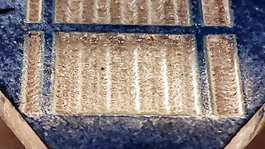
The sine bars at 400 mm/s come out very shallow, both rectangular bars have sloped edges, and the 1 mm bar on the left resembles a V:
Sine bars – acrylic – 400 mm-s 100pct
At 100 mm/s, all the features are nicely shaped, although the sidewalls still have some slope:
Sine bars – acrylic – 100 mm-s 25pct
In all fairness, grayscale engraving with a CO₂ laser may not be particularly useful, unless you’re making very shallow and rather grainy 3D relief maps.
Intensity-modulating a “photographic” engraving on, say, white tile depends on the dye / metal / whatever having a linear-ish intensity variation with exposure, which is an unreasonable assumption.
The L-ON digital enable also has a millisecond or two of ramp time, so each discrete dot within a halftoned / dithered image has a minimum width.