Based on the poor performance of the NB-5L batteries I bought from Blue Nook, they sent me three NB-5L batteries from a fresh batch (date code BNI13) and I ran them through the same discharge test:
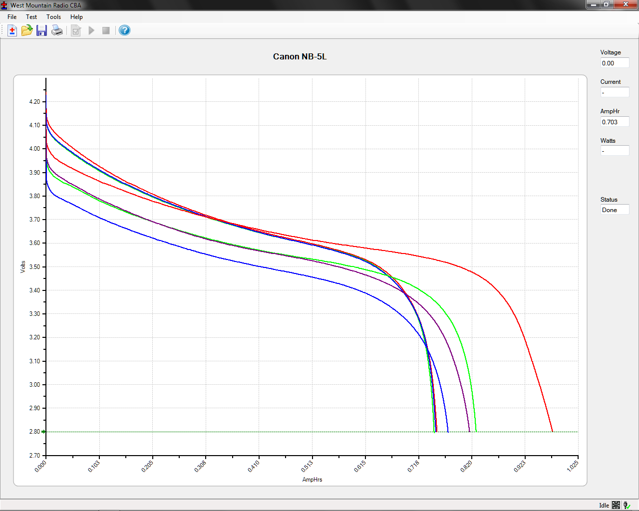
The red line off to the far right is the three year old Canon OEM battery, which remains far and away the best battery at 1 A·h.
The previous cells (BNF27) produced the three scattered traces with the lowest initial voltages, ending around 0.8 A·h.
The new cells (BNI13) produced the three tightly clustered traces. They have a higher initial voltage than the OEM cell, but much lower total capacity (about 0.75 A·h).
These batteries obviously don’t come close to their 1400 mA·h rating. The capacity depends on the load current, but I’m using 500 mA because that’s close to the camera’s drain; the results should correlate reasonably well with actual use.
The higher voltage from the new batteries will produce a longer runtime than the previous duds, but their total capacity is lower and they’re still no match for the old Canon OEM battery.
The new ones start out very similar to each other, but the previous batch hasn’t aged well on their shelf. If the date codes mean what I think, all of these batteries will fail quickly.
All that’s quite disappointing, because their NP-BX1 batteries for the Sony camera turned out quite well. The date codes all have the same format and typography, so I think they come from the same factory.
For whatever it’s worth, I think the date coding works like this:
- B – factory? shift? OEM? Blue Nook?
- M – last two digits of year: M=13, N=14
- K – month: F=6, I=9, K=11
- 20 – day
For the four batteries / lots I have on hand:
BMK20= 2013 Nov 20 – NP-BX1 bought in early 2014BNI18= 2014 Sep 18 – NP-BX1 bought in October – new lotBNF27= 2014 Jun 27 – NB-5L bought in October – old lotBNI13= 2014 Sep 13 – NB-5L supplied in late October – new lot
So it goes.