A quick-and-dirty bracket (made from a leftover strip in the pile of chassis clips) affixed an IR reflective sensor (based on the ubiquitous TCRT5000 module) to the sewing machine motor:
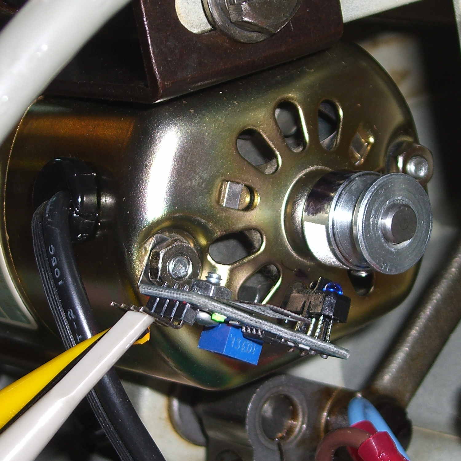
That’s scribbling black Sharpie around the retroreflective tape for the laser tachometer, which worked just about as poorly as you’d expect. Retroreflective tape, by definition, reflects the light directly back at the LED, but in this case you want it bounced to the photosensor.
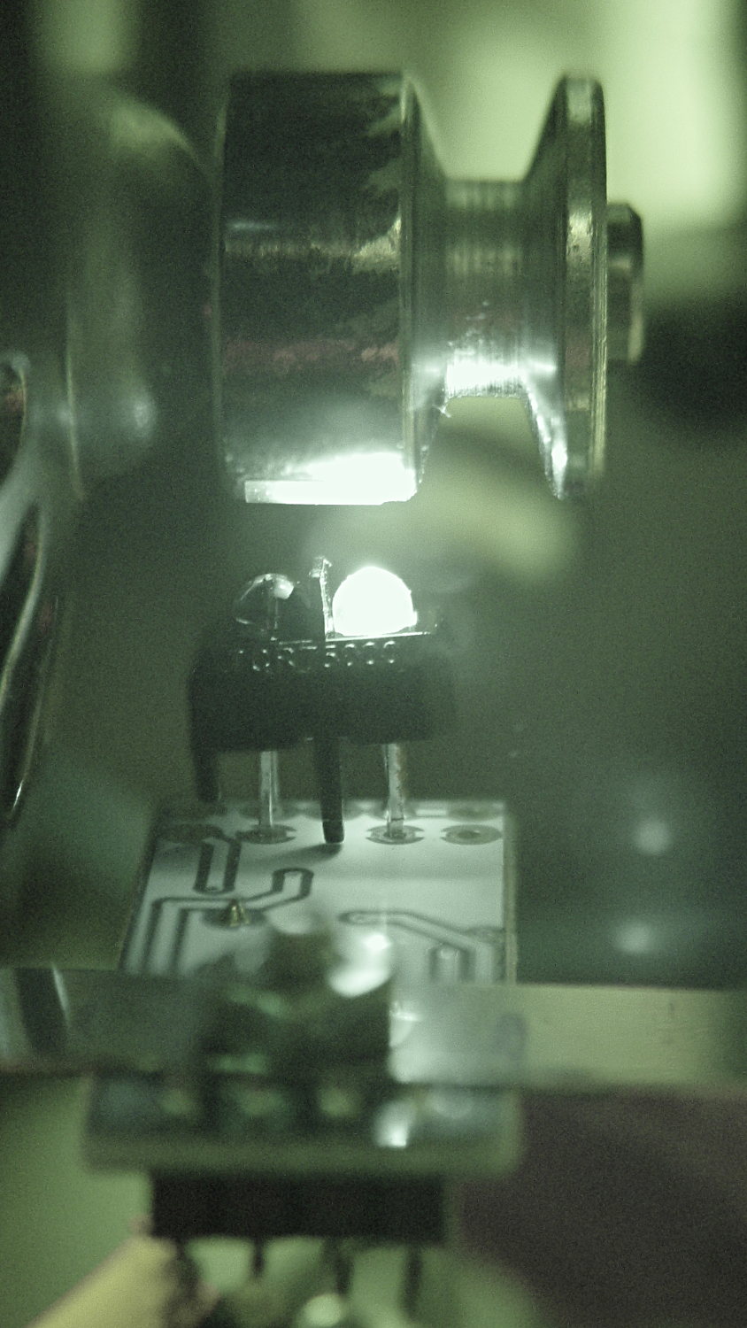
An IR view shows the geometry and highlights the LED:
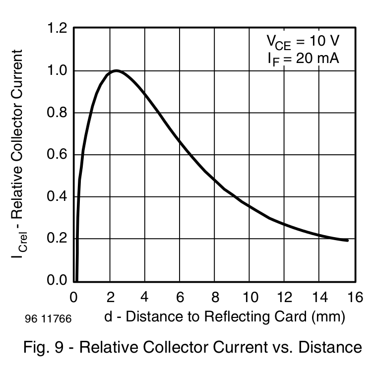
The TCRT5000 datasheet suggests that the peak operating distance is 2.5 mm, roughly attained by tinkering with the bracket. The datasheet graph shows that anything between 1 and 5 mm should be just fine:
Soooo, a bit of contrast improvement is in order:
- Scrape off the tape
- Remove adhesive and Sharpie with xylene
- Scuff with sandpaper
- Apply Brownell’s Oxpho-Blue gun bluing with a cotton swab
- Buff with 0000 steel wool
- Repeat
- Apply stainless steel tape around half the circumference
- Burnish flat
Which looks pretty good:
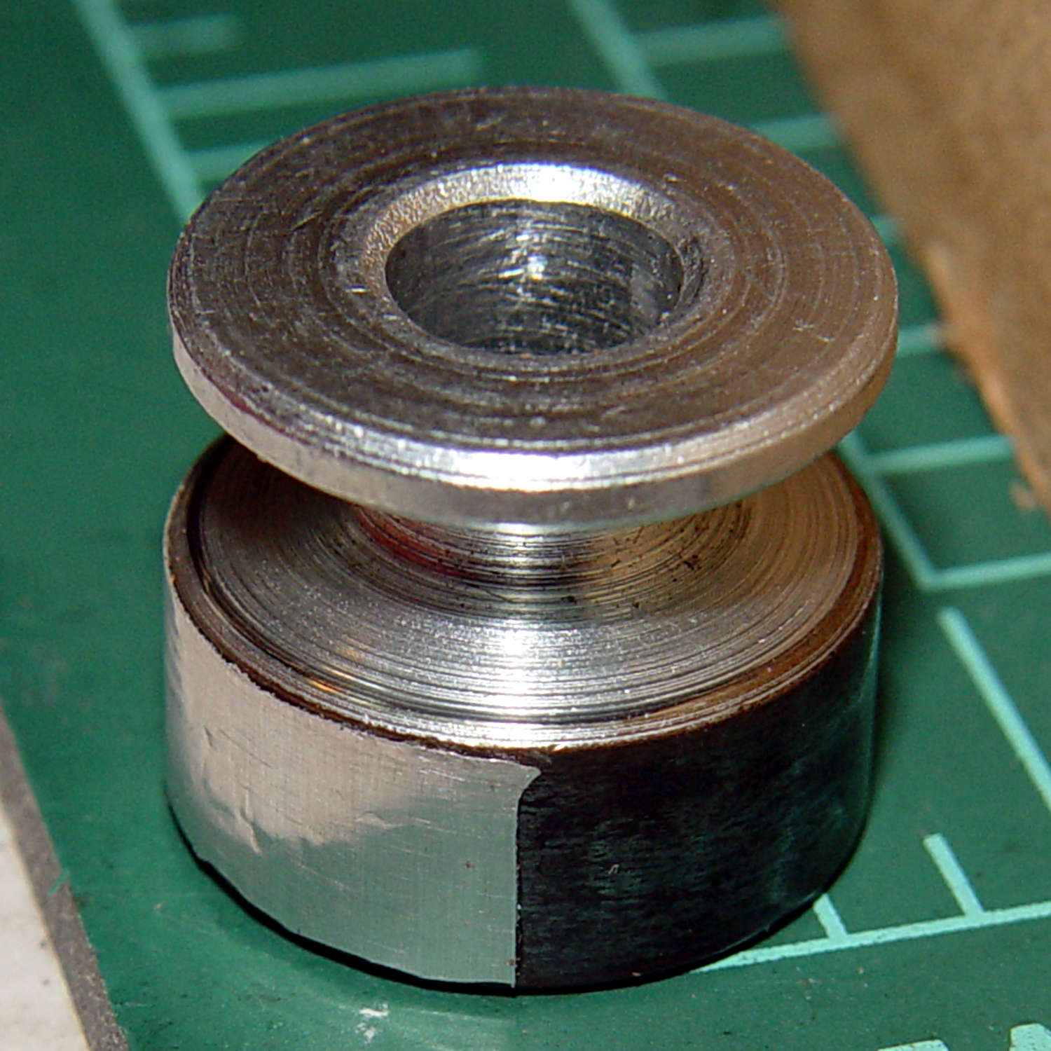
The stainless tape butts up against the setscrew:
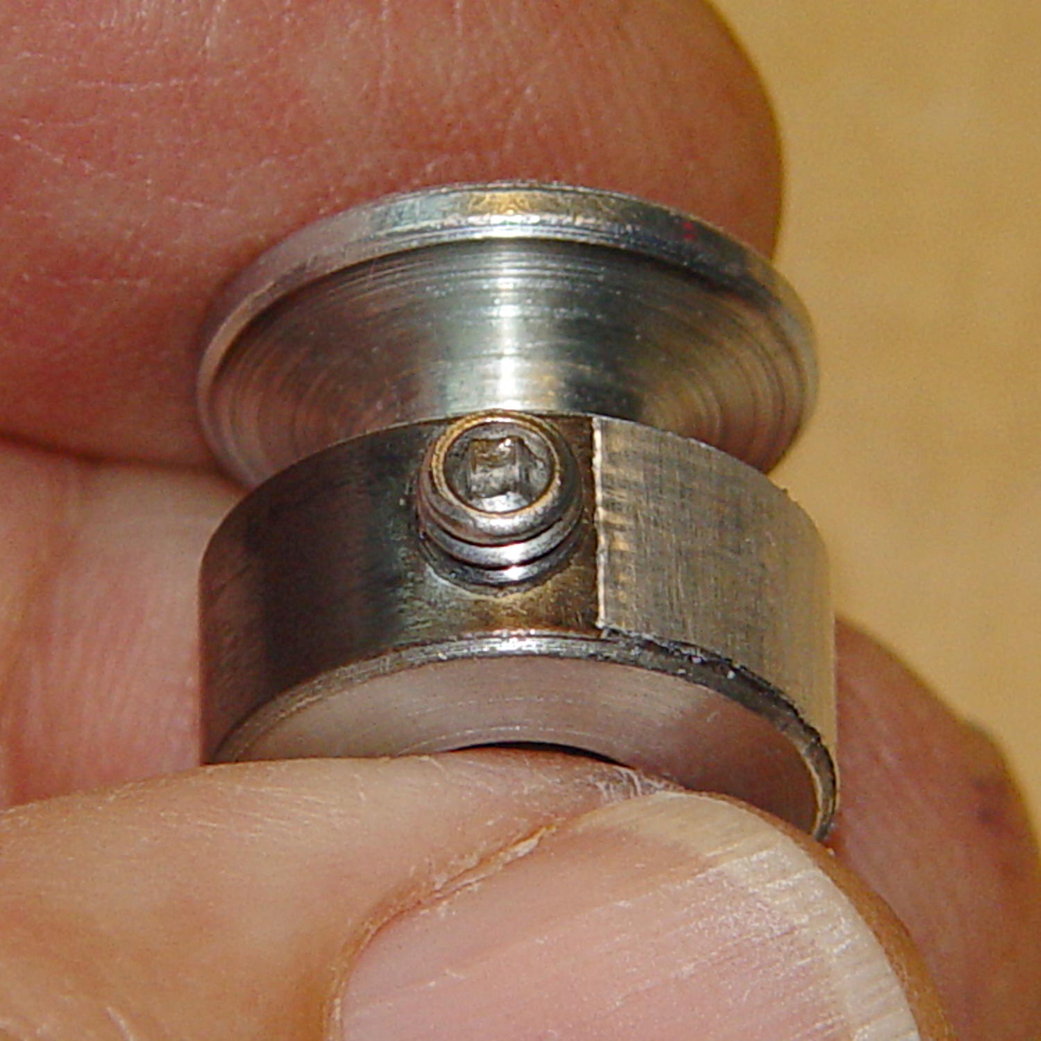
Adjusting the sensitivity midway between the point where the output is low (OFF) over the black and high (ON) over the tape seems reasonable.
Running at the slowest possible speed produces this pulse train:
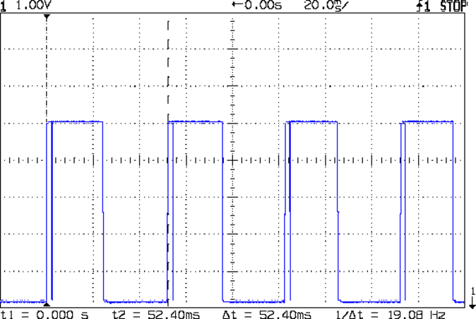
The motor at 19 rev/s = 1140 RPM corresponds to about 2 rev/s of the sewing machine shaft= 2 stitch/s. Slower than, that, the pedal won’t go in simple open-loop mode.
The setscrew causes those “glitches” on the rising edge. They look like this at a faster sweep:
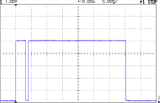
At maximum speed, the setscrew doesn’t show up:
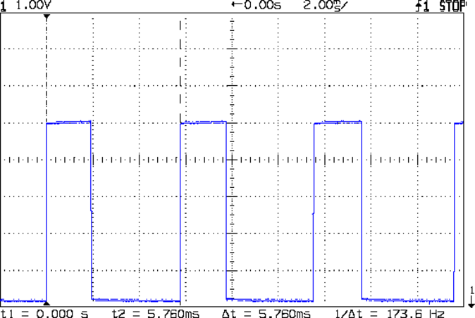
The motor at 174 rev/s = 10440 RPM would do 1000 stitch/s, but that’s just crazy talk: it runs at that speed with the handwheel clutch disengaged and the motor driving only the bobbin winder. I was holding the machine down with the shaft engaged and all the gimcrackery flailing around during that shot.
The sensor board may have an internal glitch filter, but it’s hard to say: the eBay description has broken links to the circuit documentation.
I could grind the setscrew flush with the pulley OD and cover it with tape, but that seems unreasonable. Fixing the glitch in firmware shouldn’t be too difficult: ignore a rising edge that occurs less than, say, 1/4 of the previous period following the previous edge.
Perhaps buffing half the pulley’s circumference to a reasonable shine (minus the bluing) would eliminate the need for the stainless steel tape.
Iterating the bluing operation / scrubbing with steel wool should produce a darker black, although two passes yields a nice flat black.

Comments
6 responses to “Sewing Machine RPM Sensing: Gun Bluing FTW!”
I can reduce the number of steps to improve contrast:
1) Apply black heatshrink tube to the pulley
2) Apply white correction tape to a portion of the heatshrink tube
Not sure about the setscrew, unless you can use it to trigger a Hall-effect sensor.
The gotcha here is a 10 kRPM top speed: the more stuff attached to the pulley, the more stuff will eventually peel off.
I know for a fact that the stainless steel tape adhesive eventually dries out, which is why buffing half the pulley seems more durable: gun bluing should survive forever inside a sewing machine. With a bit of luck, that will provide enough contrast without using anything that will fly off.
Well, heatshrink shouldn’t peel off as it would be a complete piece, encircling the pulley. And correction tape is essentially massless. But yes, if you can make the light and dark parts intrinsic to the pulley itself then that’s a benefit.
Based on the scope traces, wouldn’t you be better off with the setscrew somewhere in the middle of the dark part? Unless the edge of the screw is giving you the first high pulse, followed by a low for the screw itself, followed by the light tape.
As nearly as I can tell from manually turning the shaft, the setscrew recess is reflective enough to trip the sensor. I tried blackening it, with little to show for the effort; the recess must act like a corner reflector.
After some doodling, the interrupt handler now rejects glitches on either edge, so the software fix seems to work fine; more on that later. With a bit of luck, the code won’t fly apart at high speeds. [grin]
Could you point the sensor at the end face of the pulley? Then paint two semicircles of black and white on that face. There is no set screw there, and anything you stick on the face will be subject to shear force instead of a peeling force. I suppose there might not be room beyond the face of the pulley.
Or how about pointing the sensor into the motor, through those vent holes? It looks like there are some vanes in there you could dab some white paint on.
Or carry on with the current, now working, plan.
I wanted to do that, too, but the sensor on the board points kinda-sorta the wrong way for an end mount and cries out for rewiring and another 3D printed bracket. This orientation and coloration pretty much works, even though I’m not ecstatic about it, either.
The peering-into-the-vanes idea might actually work; if I need a higher resolution motor sensor, that’s definitely in the running. Thanks for the idea!