Ed Nisley's Blog: Shop notes, electronics, firmware, machinery, 3D printing, laser cuttery, and curiosities. Contents: 100% human thinking, 0% AI slop.
The shelf that collects old hard drives filled up, so I’ve been wiping the data before recycling them. This takes a while, but we know what happens when your hardware falls into unexpected hands. The routine goes a little something like this…
Set the drive’s jumper to Master, plug the drive into the USB adapter, plug the adapter directly into a USB port on the PC (because outboard hubs tend to be flaky), make sure there’s no valuable data, unmount.
time sudo dd if=/dev/urandom of=/dev/sdc bs=4096
[sudo] password for ed:
dd: error writing ‘/dev/sdc’: No space left on device
73259047+0 records in
73259046+0 records out
300069052416 bytes (300 GB) copied, 22276.7 s, 13.5 MB/s

real	371m19.003s
user	0m22.884s
sys		370m34.906s
Good old dd works for me; the only trick is not obliterating the system’s main hard drive with a simple finger fumble. Numbers from /dev/urandom suffice for this purpose; that’s where most of the packaged programs get their data, too. I do hardcore style, just because.
Ordinary desktop drives, at least those from long ago, can write at a bit over 12 MB/s → 40 GB/h on the average, with the higher peak rates that generally appear in the drive descriptions remaining an occasional sight. They won’t go much faster, even when plugged directly into the system board, but it’s not as if I sit there waiting until it’s done. USB 2.0 “high speed” transfers can hit 60 MB/s, including all the overhead, so that’s not the limiting factor; I’d expect the adapter’s firmware to throttle the data long before the bus strangles.
Use gparted to write a fresh partition table with a single NTFS (because the next user will probably run Windows) partition labeled Scrubbed spanning the entire drive.
Then stack the drive neatly on the outbound heap:
Scrubbed hard drives
That cardboard box isn’t quite as full of unscrubbed drives as it was a few weeks ago.
The stack in the back contains all those worthless 30 to 80 GB 5400 RPM drives from old Dells, plus a few 1.5 and 2.0 (!) GB drives from who knows where. I have a plan for those platters…
If the 1-48 on the side of the tube base (facing away in the picture) means anything, then General Electric built it in January 1948.
The pinout view in the datasheet assumes you’re looking at the bottom of the socket, which makes perfect sense given the hand-wired chassis construction techniques of the day:
0D3 Voltage Regulator Tube – pinout
So the view is backwards when seen from the top, not that you’d ever need it:
Ceramic octal tube socket – 0D3 pinout
The internal jumper across pins 3-7 allows you to disconnect the downstream circuit when the regulator isn’t in the socket, which is a Very Good Idea with a shunt regulator.
Not having a 200 V power supply ready to hand, but having recently restocked the 9 V alkaline battery box, this actually worked:
0D3 voltage regulator test setup
That’s 16 x 9-ish V = 150 V across the battery terminals, plus a 50 V adjustable bench power supply coming in on clip leads from the upper right, with current shown on a digital panel meter across a 1 Ω sense resistor. The classic 1.5 kΩ carbon resistor emerged from from a coffee can of parts that Came With The House™ and seemed appropriate for the occasion.
The tube conducts a few milliamps through a small plasma filament discharge at 150 V. The current ramps up to about 10 mA as the supply voltage increases to 180 V, whereupon the tube fires and the current jumps to 30 mA (which is less than the spec, but I ran the power supply in constant-current mode to avoid whoopsies).
Reducing the current to 10 mA slightly reduces the area involved in the plasma discharge, but the tube still produces a nice display through the mica spacer / insulator atop the plate:
0D3 voltage regulator – 10 mA current
That isn’t quite in focus, but should give you the general idea.
I didn’t measure the operating voltages across the tube, mostly because I didn’t want more cheap clip leads cluttering the bench.
It’d make a very low intensity nightlight that dissipates a watt or two. Boosting the current to the absolute maximum 40 mA would brighten it up a bit, but dissipating 6 W in the tube probably won’t do it any good.
This obviously calls for an Arduino monitoring the tube current with a Hall-effect sensor and regulating it with a hulking MOSFET…
Back in the day, this surely represented an achievement in high-density electronics packaging:
Electronics Block – 1
A view from the other corner suggests the layout wasn’t quite right:
Electronics Block – 2
It has no identification, the transistors have house numbers, and the PCB looks like a prototype. As nearly as I can tell from the capacitor date codes, it dates back to the mid-1960s.
Judging from the ugly solder and dislodged via rings, somebody had to apply extensive modifications after initial assembly; it trailed half a dozen red wires soldered to vias and components.
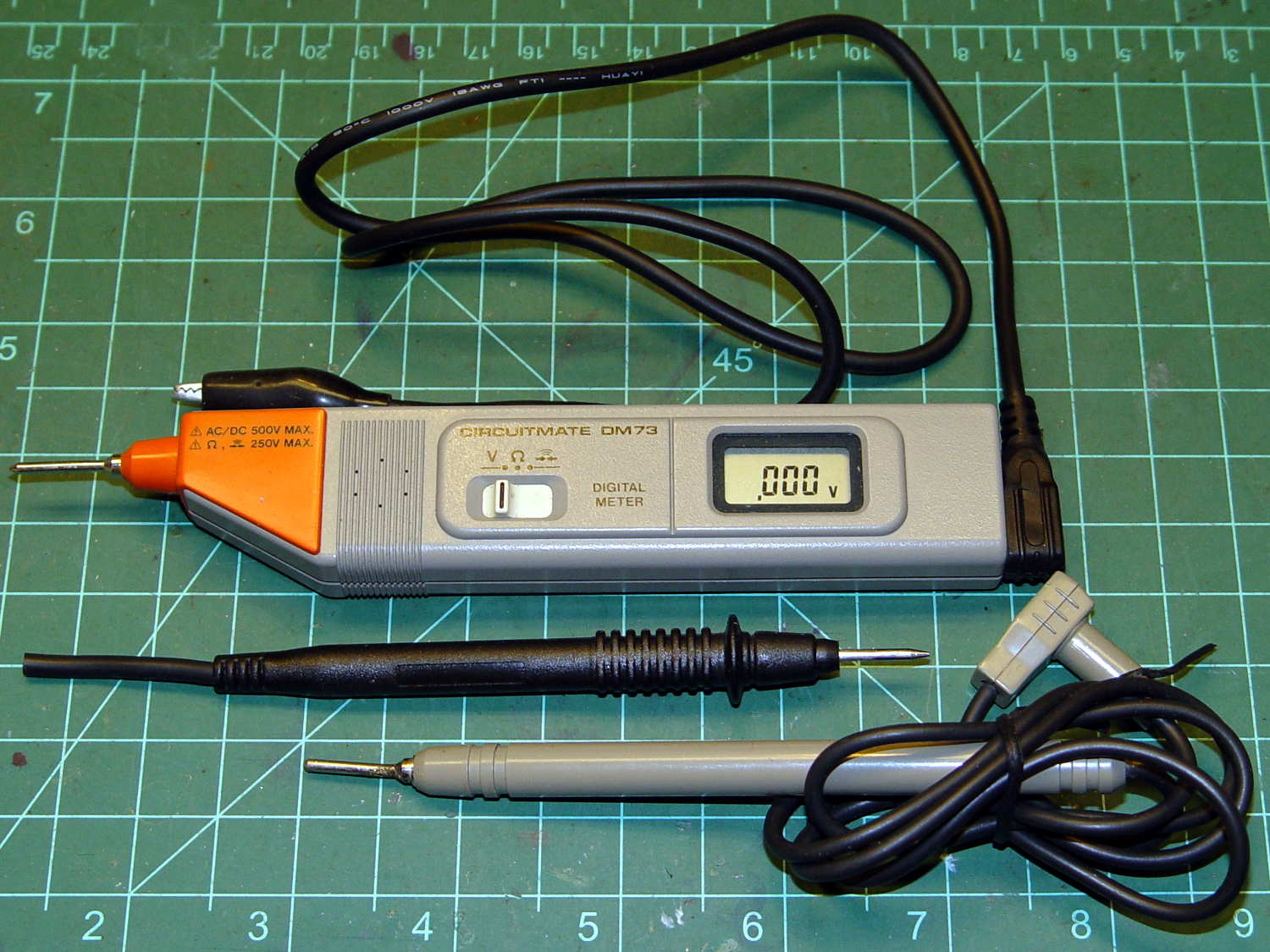
Although it’s rated to 500 V, it violates the fundamental principle of high-voltage electronics debugging:
Always keep one hand in your pocket!
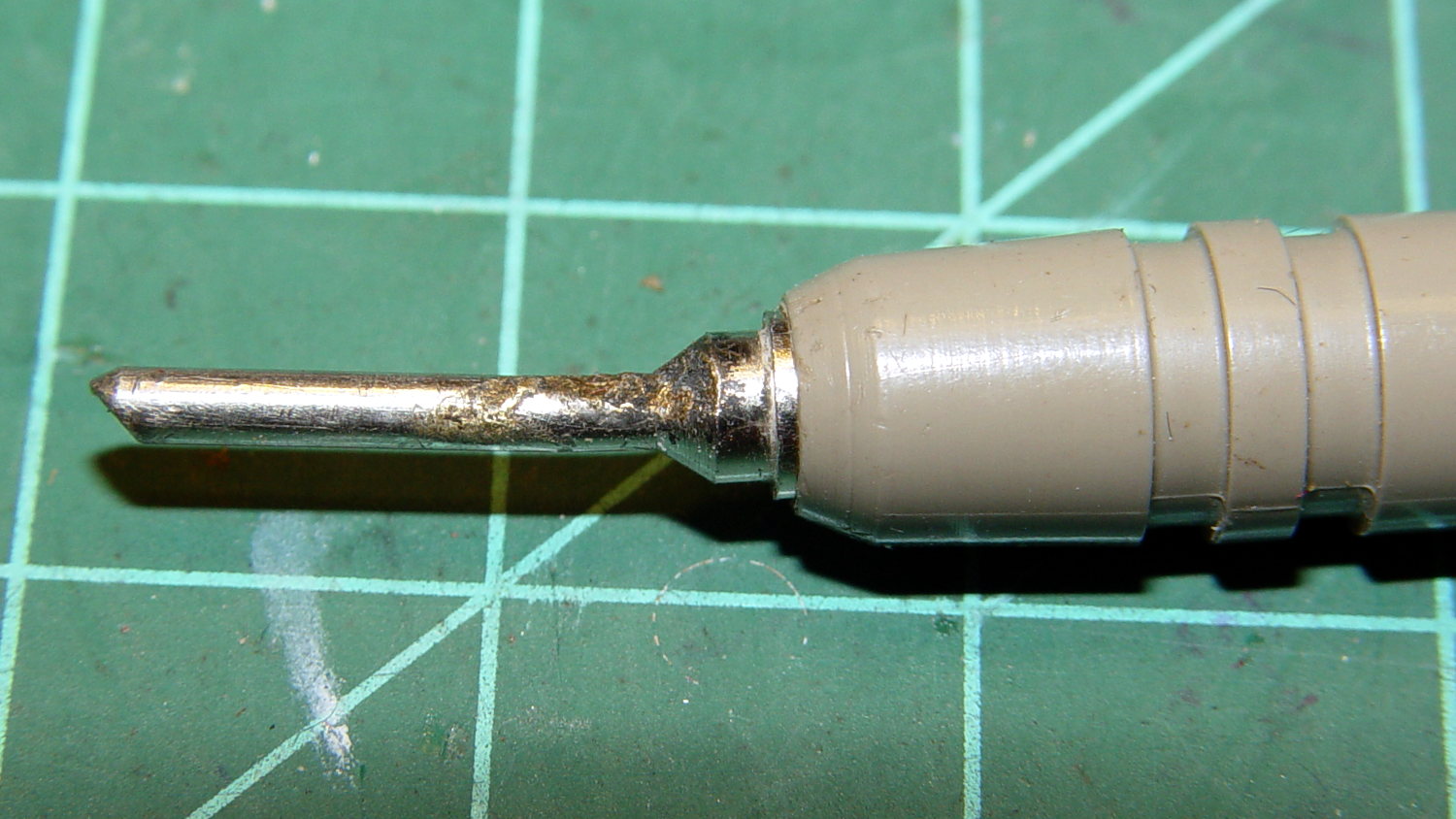
The scorched and truncated probe tip on the “ground wire” shows Phil slipped at least once:
Beckman DM73 – probe tip
After far too long, I sacrificed a black multimeter probe from the heap, soldered an alligator clip on the end, and, henceforth, will use it appropriately. Mostly, I never do any high-voltage work, but you never know.
I suppose I should splice that nice black probe onto the end of the Beckman wire for low-voltage work…
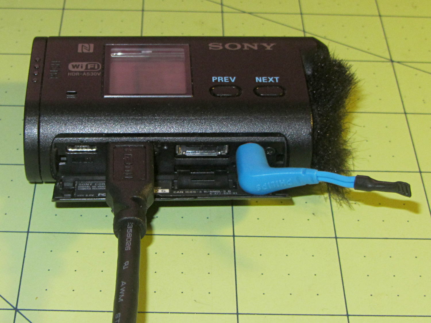
The Sony HDR-AS30V has extremely high audio gain, which is precisely what you need for the mic on an action camera. It sends that audio, along with the video, through its HDMI output, so when you drive a display from the camera in enclosed space, the audio is REALLY LOUD and causes severe feedback. For obscure reasons, given the staggering cost of the venue’s AV system, there’s no way to mute the audio channel of the video input when you’re also using a mic attached to someone giving a presentation.
The obvious solution, a shorted jumper (formerly an earbud plug) in the external mic jack, looked like this:
Sony HDR-AS30V – Dummy external mic
Contrary to what I expected, the camera doesn’t disable the internal mic with the jumper in place. The amp probably uses an analog multiplexer, rather than a mechanical switch, and even an off-channel isolation of, say, 76 dB (from the MAX4544 spec, for example) isn’t enough to completely mute the mic. You could, given sufficient motivation, measure the actual isolation, but the surviving audio isn’t subtle at all.
The not-obvious solution turned out to be putting the camera into either single or interval photo mode, rather than the movie mode I use for bike rides. It seems that when the video format doesn’t require audio, the camera either disables the audio inputs or (more likely) just doesn’t include audio data in the HDMI output.
Which produces exactly what I want: a video output with no accompanying audio.
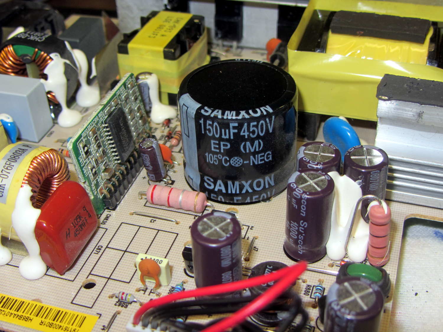
Quite some time ago, I picked up a nice monitor that turned out to be a debranded (all OEM labels removed or covered) HP w2408. It eventually became erratic, refusing to turn on or return from power-save mode, so I took it apart. All the caps looked good and seemed to have low ESR, except for the big one in the middle of the power supply board:
HP 2408 monitor power supply – HV cap
It’s 30 mm in diameter, with 10 mm lead spacing, and stands a squat 26 mm tall, ignoring a millimeter or two of bulge in its should-be-flat black cap:
HP 2408 monitor power supply – HV cap bulge
Having never seen one of that size before, I sent a note and picture to folks who sell re-capping kits for monitors, in the hope that they’ll have a lead.
// Random LED Dots - from noise source
// Ed Nisley - KE4ANU - September 2015

//----------
// Pin assignments

const byte PIN_HEARTBEAT = 8;		// DO - heartbeat LED
const byte PIN_SYNC = A3;			// DO - scope sync

const byte PIN_LATCH  = 4;			// DO - shift register latch clock

const byte PIN_DIMMING = 9;			// AO - LED dimming control

// These are *hardware* SPI pins

const byte PIN_MOSI = 11;			// DO - data to shift reg
const byte PIN_MISO = 12;			// DI - data from shift reg - sampled noise input
const byte PIN_SCK  = 13;			// DO - shift clock to shift reg (also Arduino LED)
const byte PIN_SS = 10;				// DO - -slave select (must be positive for SPI output)

//----------
// Constants

#define DISPLAY_MS 10000ul

//----------
// Globals

// Input noise bits can produce one of four possible conditions
//  Use the von Neumann extractor, discarding 00 and 11 sequences
// https://en.wikipedia.org/wiki/Randomness_extractor#Von_Neumann_extractor
// Sampling interval depends on SPI data rate
// LSB arrives first, so it's the earliest sample

#define VNMASK_A 0x00000001
#define VNMASK_B 0x01000000

enum sample_t {VN_00,VN_01,VN_10,VN_11};

typedef struct {
	byte BitCount;					// number of bits accumulated so far
	unsigned Bits;					// random bits filled from low order upward
	int Bias;						// tallies 00 and 11 sequences to measure analog offset
   unsigned SampleCount[4];	// number of samples in each bin
} random_t;

random_t RandomData;

// LED selects are high-active bits and low-active signals: flipped in UpdateLEDs()
// *exactly* one row select must be active in each element

typedef struct {
	const byte Row;
	byte ColR;
	byte ColG;
	byte ColB;
} leds_t;

// altering the number of rows & columns will require substantial code changes...
#define NUMROWS 8
#define NUMCOLS 8

leds_t LEDs[NUMROWS] = {
	{0x80,0,0,0},
	{0x40,0,0,0},
	{0x20,0,0,0},
	{0x10,0,0,0},
	{0x08,0,0,0},
	{0x04,0,0,0},
	{0x02,0,0,0},
	{0x01,0,0,0},
};

byte RowIndex;

#define LEDS_ON 0
#define LEDS_OFF 255

unsigned long MillisNow;
unsigned long DisplayBase;

//-- Helper routine for printf()

int s_putc(char c, FILE *t) {
  Serial.write(c);
}

//-- Useful stuff

// Free RAM space monitor
//  From http://playground.arduino.cc/Code/AvailableMemory

uint8_t * heapptr, * stackptr;

void check_mem() {
  stackptr = (uint8_t *)malloc(4);          // use stackptr temporarily
  heapptr = stackptr;                     // save value of heap pointer
  free(stackptr);      // free up the memory again (sets stackptr to 0)
  stackptr =  (uint8_t *)(SP);           // save value of stack pointer
}

void TogglePin(char bitpin) {
	digitalWrite(bitpin,!digitalRead(bitpin));    // toggle the bit based on previous output
}

void PulsePin(char bitpin) {
	TogglePin(bitpin);
	TogglePin(bitpin);
}

//---------
//-- SPI utilities

void EnableSPI(void) {
	digitalWrite(PIN_SS,HIGH);					// make sure this is high!
	SPCR |= 1 << SPE;
}

void DisableSPI(void) {
	SPCR &= ~(1 << SPE);
}

void WaitSPIF(void) {
	while (! (SPSR & (1 << SPIF))) {
//		TogglePin(PIN_HEARTBEAT);
		continue;
	}
}

byte SendRecSPI(byte DataByte) {					// send one byte, get another in exchange
	SPDR = DataByte;
	WaitSPIF();
	return SPDR;									// SPIF will be cleared
}

//---------------
// Update LED shift registers with new data
// Returns noise data shifted in through MISO bit

unsigned long UpdateLEDs(byte i) {

unsigned long NoiseData = 0ul;

	NoiseData |= (unsigned long) SendRecSPI(~LEDs[i].ColB);				// correct for low-active outputs
	NoiseData |= ((unsigned long) SendRecSPI(~LEDs[i].ColG)) << 8;
	NoiseData |= ((unsigned long) SendRecSPI(~LEDs[i].ColR)) << 16;
	NoiseData |= ((unsigned long) SendRecSPI(~LEDs[i].Row))  << 24;

	analogWrite(PIN_DIMMING,LEDS_OFF);			// turn off LED to quench current
	PulsePin(PIN_LATCH);						// make new shift reg contents visible
	analogWrite(PIN_DIMMING,LEDS_ON);

	return NoiseData;
}

//---------------
// Extract random data from sampled noise input
//  ... tuck it into the global bit structure
// Returns von Neumann status of the sample

byte ExtractRandomBit(unsigned long RawSample) {

byte RetVal;

	switch (RawSample & (VNMASK_A | VNMASK_B)) {
	case 0:							// 00 - discard
		RetVal = VN_00;
		RandomData.Bias--;
		break;
	case VNMASK_A:					// 10 - true
		RetVal = VN_10;
		RandomData.BitCount++;
		RandomData.Bits = (RandomData.Bits << 1) | 1;
		break;
	case VNMASK_B:					// 01 - false
		RetVal = VN_01;
		RandomData.BitCount++;
		RandomData.Bits  = RandomData.Bits << 1;
		break;
	case (VNMASK_A | VNMASK_B):		// 11 - discard
		RetVal = VN_11;
		RandomData.Bias++;
		break;
	}

	RandomData.Bias = constrain(RandomData.Bias,-9999,9999);
	RandomData.SampleCount[RetVal]++;
	RandomData.SampleCount[RetVal] = constrain(RandomData.SampleCount[RetVal],0,63999);

	return RetVal;
}

//---------------
// Set LED from random bits
// Assumes the Value contains at least nine low-order random bits
// On average, this leaves the LED unchanged for 1/8 of the calls...

void SetLED(unsigned Value) {

byte Row =   Value        & 0x07;
byte Col =   (Value >> 3) & 0x07;
byte Color = (Value >> 6) & 0x07;

byte BitMask = (0x80 >> Col);

//	printf("%u %u %u %u\r\n",Row,Col,Color,BitMask);

	LEDs[Row].ColR &= ~BitMask;
	LEDs[Row].ColR |= (Color & 0x04) ? BitMask : 0;

	LEDs[Row].ColG &= ~BitMask;
	LEDs[Row].ColG |= (Color & 0x02) ? BitMask : 0;

	LEDs[Row].ColB &= ~BitMask;
	LEDs[Row].ColB |= (Color & 0x01) ? BitMask : 0;

}

//------------------
// Set things up

void setup() {

	pinMode(PIN_HEARTBEAT,OUTPUT);
	digitalWrite(PIN_HEARTBEAT,HIGH);		// show we arrived

	pinMode(PIN_SYNC,OUTPUT);
	digitalWrite(PIN_SYNC,LOW);

	pinMode(PIN_MOSI,OUTPUT);				// SPI-as-output is not strictly necessary
	digitalWrite(PIN_MOSI,LOW);

	pinMode(PIN_SCK,OUTPUT);
	digitalWrite(PIN_SCK,LOW);

	pinMode(PIN_SS,OUTPUT);
	digitalWrite(PIN_SS,HIGH);				// OUTPUT + HIGH is required to make SPI output work

	pinMode(PIN_LATCH,OUTPUT);
	digitalWrite(PIN_LATCH,LOW);

	Serial.begin(57600);
	fdevopen(&s_putc,0);					// set up serial output for printf()

	printf("Noisy LED Dots\r\nEd Nisley - KE4ZNU - September 2015\r\n");

//-- Set up SPI hardware
// LSB of SPCR set bit clock speed:
//  00 = f/4
//  01 = f/16
//  10 = f/64
//  11 = f/128

	SPCR = B01110011;						// Auto SPI: no int, enable, LSB first, master, + edge, leading, speed
	SPSR = B00000000;						// not double data rate

	EnableSPI();							// turn on the SPI hardware

	SendRecSPI(0);							// set valid data in shift registers: select Row 0, all LEDs off

//-- Dimming pin must use fast PWM to avoid beat flicker with LED refresh rate
//   Timer 1: PWM 9 PWM 10

	analogWrite(PIN_DIMMING,LEDS_OFF);		// disable column drive (hardware pulled it low before startup)

	TCCR1A = B10000001; 					// Mode 5 = fast 8-bit PWM with TOP=FF
	TCCR1B = B00001001; 					// ... WGM, 1:1 clock scale -> 64 kHz

//-- lamp test: send a white flash through all LEDs
//	 collects noise data to get some randomness going

	printf("Lamp test begins: white flash each LED...");

	digitalWrite(PIN_HEARTBEAT,LOW);		// turn off while panel blinks

	analogWrite(PIN_DIMMING,LEDS_ON);		// enable column drive

	for (byte i=0; i<NUMROWS; i++) {
		for (byte j=0; j<NUMCOLS; j++) {
			LEDs[i].ColR = LEDs[i].ColG = LEDs[i].ColB = 0x80 >> j;
			for (byte k=0; k<NUMROWS; k++) {
				ExtractRandomBit(UpdateLEDs(k));
				delay(25);
			}
		LEDs[i].ColR = LEDs[i].ColG = LEDs[i].ColB = 0;
		}
	}
	UpdateLEDs(NUMROWS-1);					// clear the last LED

	printf(" done!\r\n");

//-- Preload LEDs with random values
//   We take whatever number of random bits arrived in RandomData during lamp test

	digitalWrite(PIN_HEARTBEAT,LOW);
	printf("Preloading LED array\r\nRandom bits %04x\r\n",RandomData.Bits);

	randomSeed(RandomData.Bits);

	for (byte Row=0; Row<NUMROWS; Row++) {
		for (byte Col=0; Col<NUMCOLS; Col++) {		// Col runs backwards, but we don't care
			LEDs[Row].ColR |= random(2) << Col;
			LEDs[Row].ColG |= random(2) << Col;
			LEDs[Row].ColB |= random(2) << Col;
		}
		UpdateLEDs(Row);
	}

	RandomData.BitCount = 0;
	RandomData.Bits = 0;
	RandomData.Bias = 0;
   for (byte i=0; i<4; i++) {
	   RandomData.SampleCount[i] = 0;
   }

	check_mem();
	printf("SP: %u HP: %u Free RAM: %u\r\n",stackptr,heapptr,stackptr - heapptr);

	printf("Running...\r\n");

	DisplayBase = millis();

}

//------------------
// Run the test loop

void loop() {

byte ThisBit;

	MillisNow = millis();

	if (RowIndex >= NUMROWS) {							// set up LED row index for this pass
		RowIndex = 0;
		PulsePin(PIN_SYNC);
	}

	if ((MillisNow - DisplayBase) >= DISPLAY_MS) {
		analogWrite(PIN_DIMMING,LEDS_OFF);				// turn off LED to prevent bright glitch
		printf("Bias: %5d of %5u - %5u %5u %5u %5u\r\n",
         RandomData.Bias,
         RandomData.SampleCount[VN_00] + RandomData.SampleCount[VN_11],
         RandomData.SampleCount[0],
         RandomData.SampleCount[1],
         RandomData.SampleCount[2],
         RandomData.SampleCount[3]
         );
		RandomData.Bias = 0;
      for (byte i=0; i<4; i++) {
         RandomData.SampleCount[i] = 0;
      }
 //		check_mem();
//		printf("SP: %u HP: %u Free RAM: %u\r\n",stackptr,heapptr,stackptr - heapptr);
		DisplayBase = MillisNow;
	}

// Update one LED row per pass, get at most one random bit

	ThisBit = ExtractRandomBit(UpdateLEDs(RowIndex++));

// Update the heartbeat LED to show bit validity

	switch (ThisBit) {
		case VN_00:
		case VN_11:
			digitalWrite(PIN_HEARTBEAT,HIGH);
			break;
		case VN_01:
		case VN_10:
			digitalWrite(PIN_HEARTBEAT,LOW);
			break;
	}

// If we have enough random data, twiddle one LED

	if (RandomData.BitCount >= 9) {
//		analogWrite(PIN_DIMMING,LEDS_OFF);				// turn off LED array to prevent bright glitch

		SetLED(RandomData.Bits);
		RandomData.BitCount = 0;
		RandomData.Bits = 0;
	}

	digitalWrite(PIN_HEARTBEAT,LOW);

}