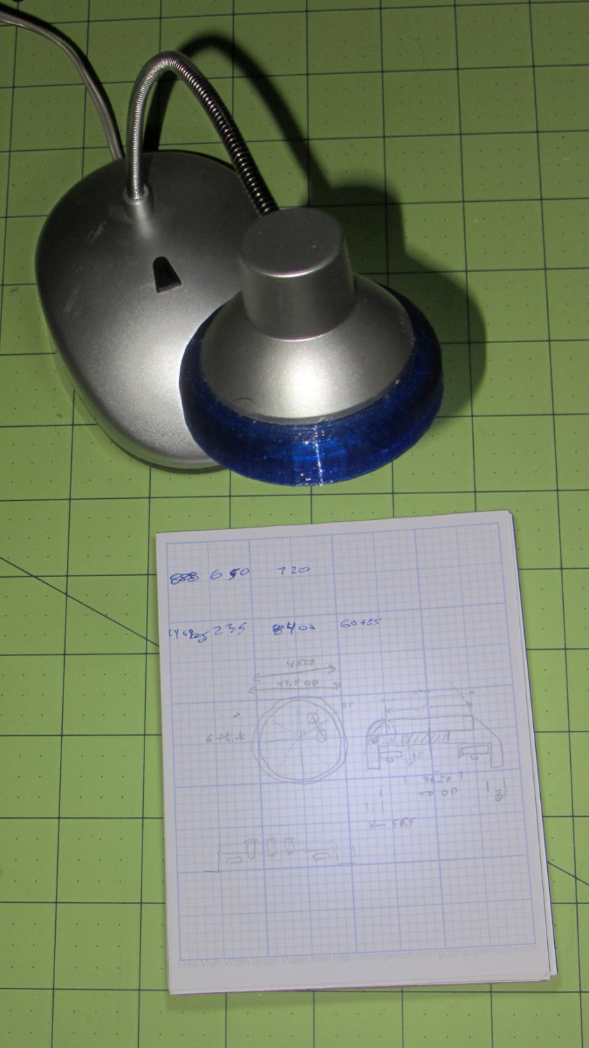
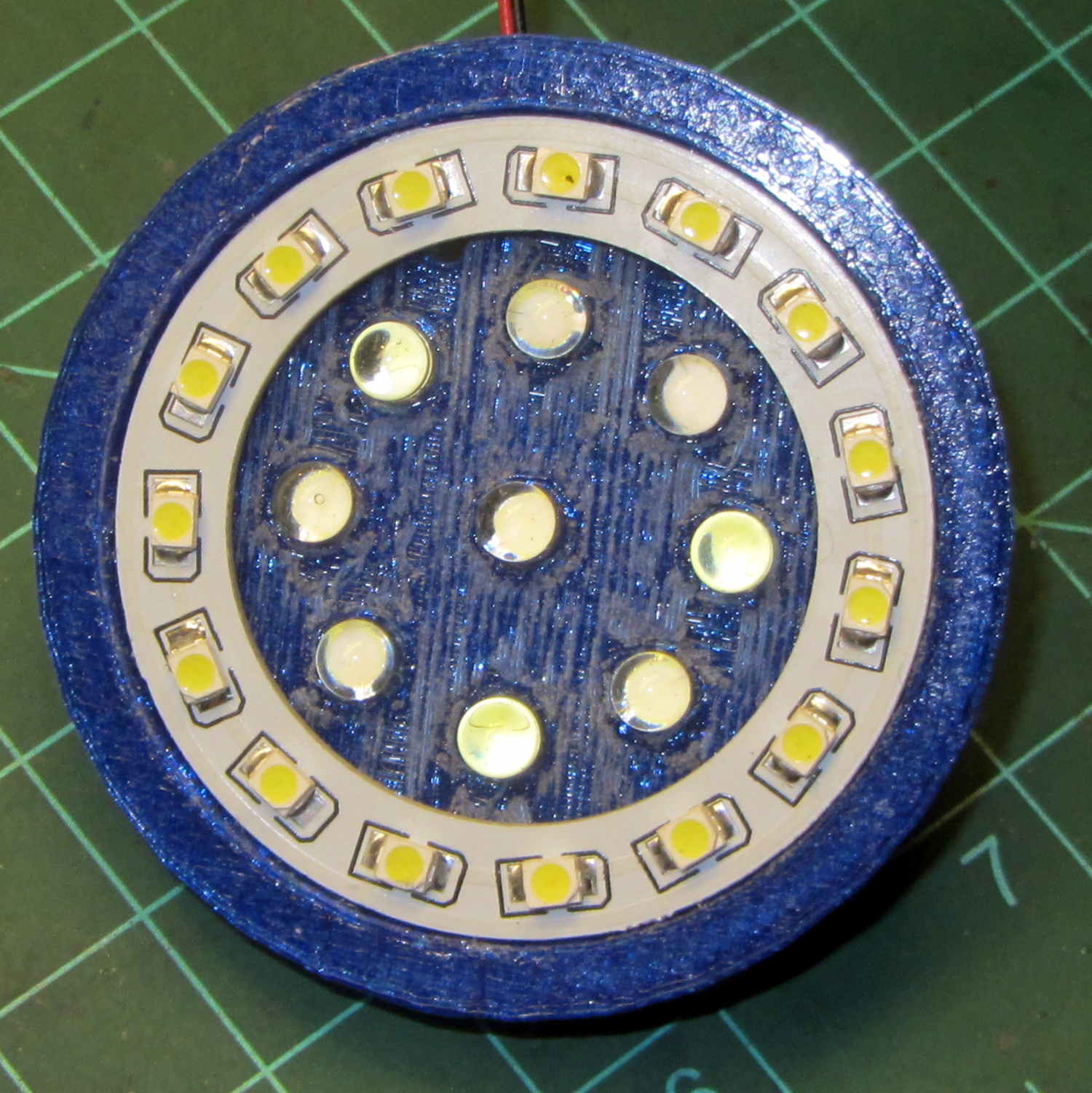
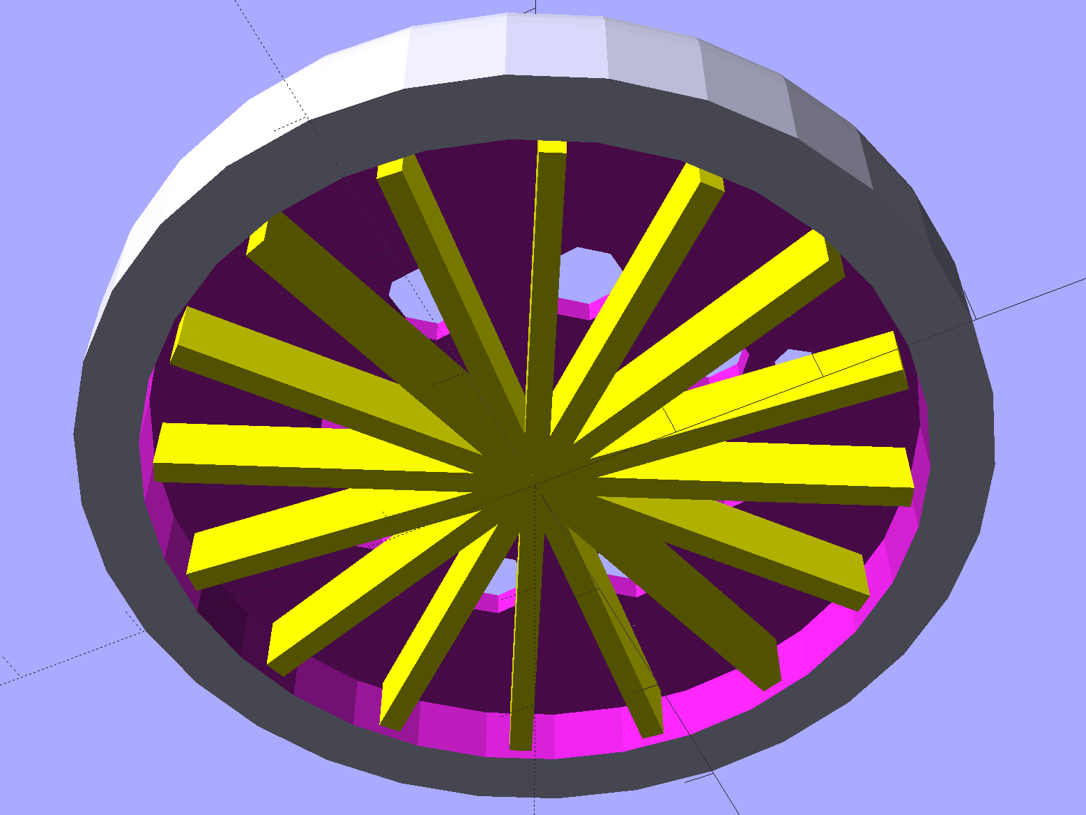
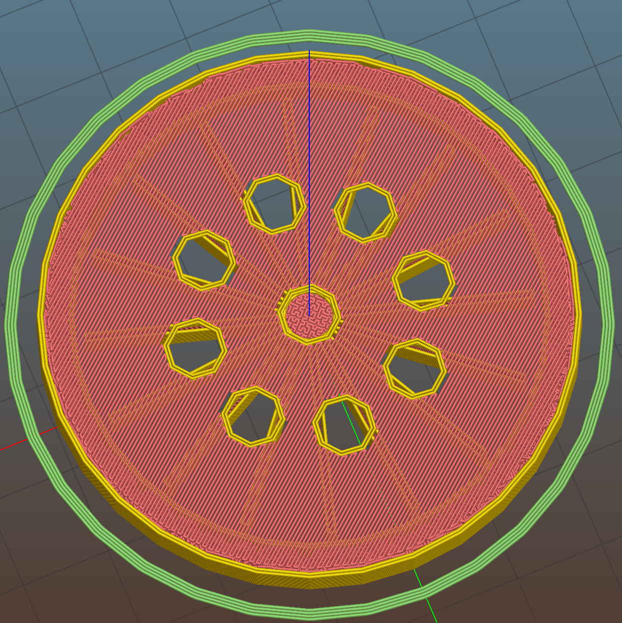
Ed Nisley's Blog: Shop notes, electronics, firmware, machinery, 3D printing, laser cuttery, and curiosities. Contents: 100% human thinking, 0% AI slop.
Back in the day, this surely represented an achievement in high-density electronics packaging:
Electronics Block – 1
A view from the other corner suggests the layout wasn’t quite right:
Electronics Block – 2
It has no identification, the transistors have house numbers, and the PCB looks like a prototype. As nearly as I can tell from the capacitor date codes, it dates back to the mid-1960s.
Judging from the ugly solder and dislodged via rings, somebody had to apply extensive modifications after initial assembly; it trailed half a dozen red wires soldered to vias and components.
Although it’s rated to 500 V, it violates the fundamental principle of high-voltage electronics debugging:
Always keep one hand in your pocket!
The scorched and truncated probe tip on the “ground wire” shows Phil slipped at least once:
Beckman DM73 – probe tip
After far too long, I sacrificed a black multimeter probe from the heap, soldered an alligator clip on the end, and, henceforth, will use it appropriately. Mostly, I never do any high-voltage work, but you never know.
I suppose I should splice that nice black probe onto the end of the Beckman wire for low-voltage work…
The Sony HDR-AS30V has extremely high audio gain, which is precisely what you need for the mic on an action camera. It sends that audio, along with the video, through its HDMI output, so when you drive a display from the camera in enclosed space, the audio is REALLY LOUD and causes severe feedback. For obscure reasons, given the staggering cost of the venue’s AV system, there’s no way to mute the audio channel of the video input when you’re also using a mic attached to someone giving a presentation.
The obvious solution, a shorted jumper (formerly an earbud plug) in the external mic jack, looked like this:
Sony HDR-AS30V – Dummy external mic
Contrary to what I expected, the camera doesn’t disable the internal mic with the jumper in place. The amp probably uses an analog multiplexer, rather than a mechanical switch, and even an off-channel isolation of, say, 76 dB (from the MAX4544 spec, for example) isn’t enough to completely mute the mic. You could, given sufficient motivation, measure the actual isolation, but the surviving audio isn’t subtle at all.
The not-obvious solution turned out to be putting the camera into either single or interval photo mode, rather than the movie mode I use for bike rides. It seems that when the video format doesn’t require audio, the camera either disables the audio inputs or (more likely) just doesn’t include audio data in the HDMI output.
Which produces exactly what I want: a video output with no accompanying audio.
Quite some time ago, I picked up a nice monitor that turned out to be a debranded (all OEM labels removed or covered) HP w2408. It eventually became erratic, refusing to turn on or return from power-save mode, so I took it apart. All the caps looked good and seemed to have low ESR, except for the big one in the middle of the power supply board:
HP 2408 monitor power supply – HV cap
It’s 30 mm in diameter, with 10 mm lead spacing, and stands a squat 26 mm tall, ignoring a millimeter or two of bulge in its should-be-flat black cap:
HP 2408 monitor power supply – HV cap bulge
Having never seen one of that size before, I sent a note and picture to folks who sell re-capping kits for monitors, in the hope that they’ll have a lead.
// Random LED Dots - from noise source
// Ed Nisley - KE4ANU - September 2015
//----------
// Pin assignments
const byte PIN_HEARTBEAT = 8; // DO - heartbeat LED
const byte PIN_SYNC = A3; // DO - scope sync
const byte PIN_LATCH = 4; // DO - shift register latch clock
const byte PIN_DIMMING = 9; // AO - LED dimming control
// These are *hardware* SPI pins
const byte PIN_MOSI = 11; // DO - data to shift reg
const byte PIN_MISO = 12; // DI - data from shift reg - sampled noise input
const byte PIN_SCK = 13; // DO - shift clock to shift reg (also Arduino LED)
const byte PIN_SS = 10; // DO - -slave select (must be positive for SPI output)
//----------
// Constants
#define DISPLAY_MS 10000ul
//----------
// Globals
// Input noise bits can produce one of four possible conditions
// Use the von Neumann extractor, discarding 00 and 11 sequences
// https://en.wikipedia.org/wiki/Randomness_extractor#Von_Neumann_extractor
// Sampling interval depends on SPI data rate
// LSB arrives first, so it's the earliest sample
#define VNMASK_A 0x00000001
#define VNMASK_B 0x01000000
enum sample_t {VN_00,VN_01,VN_10,VN_11};
typedef struct {
byte BitCount; // number of bits accumulated so far
unsigned Bits; // random bits filled from low order upward
int Bias; // tallies 00 and 11 sequences to measure analog offset
unsigned SampleCount[4]; // number of samples in each bin
} random_t;
random_t RandomData;
// LED selects are high-active bits and low-active signals: flipped in UpdateLEDs()
// *exactly* one row select must be active in each element
typedef struct {
const byte Row;
byte ColR;
byte ColG;
byte ColB;
} leds_t;
// altering the number of rows & columns will require substantial code changes...
#define NUMROWS 8
#define NUMCOLS 8
leds_t LEDs[NUMROWS] = {
{0x80,0,0,0},
{0x40,0,0,0},
{0x20,0,0,0},
{0x10,0,0,0},
{0x08,0,0,0},
{0x04,0,0,0},
{0x02,0,0,0},
{0x01,0,0,0},
};
byte RowIndex;
#define LEDS_ON 0
#define LEDS_OFF 255
unsigned long MillisNow;
unsigned long DisplayBase;
//-- Helper routine for printf()
int s_putc(char c, FILE *t) {
Serial.write(c);
}
//-- Useful stuff
// Free RAM space monitor
// From http://playground.arduino.cc/Code/AvailableMemory
uint8_t * heapptr, * stackptr;
void check_mem() {
stackptr = (uint8_t *)malloc(4); // use stackptr temporarily
heapptr = stackptr; // save value of heap pointer
free(stackptr); // free up the memory again (sets stackptr to 0)
stackptr = (uint8_t *)(SP); // save value of stack pointer
}
void TogglePin(char bitpin) {
digitalWrite(bitpin,!digitalRead(bitpin)); // toggle the bit based on previous output
}
void PulsePin(char bitpin) {
TogglePin(bitpin);
TogglePin(bitpin);
}
//---------
//-- SPI utilities
void EnableSPI(void) {
digitalWrite(PIN_SS,HIGH); // make sure this is high!
SPCR |= 1 << SPE;
}
void DisableSPI(void) {
SPCR &= ~(1 << SPE);
}
void WaitSPIF(void) {
while (! (SPSR & (1 << SPIF))) {
// TogglePin(PIN_HEARTBEAT);
continue;
}
}
byte SendRecSPI(byte DataByte) { // send one byte, get another in exchange
SPDR = DataByte;
WaitSPIF();
return SPDR; // SPIF will be cleared
}
//---------------
// Update LED shift registers with new data
// Returns noise data shifted in through MISO bit
unsigned long UpdateLEDs(byte i) {
unsigned long NoiseData = 0ul;
NoiseData |= (unsigned long) SendRecSPI(~LEDs[i].ColB); // correct for low-active outputs
NoiseData |= ((unsigned long) SendRecSPI(~LEDs[i].ColG)) << 8;
NoiseData |= ((unsigned long) SendRecSPI(~LEDs[i].ColR)) << 16;
NoiseData |= ((unsigned long) SendRecSPI(~LEDs[i].Row)) << 24;
analogWrite(PIN_DIMMING,LEDS_OFF); // turn off LED to quench current
PulsePin(PIN_LATCH); // make new shift reg contents visible
analogWrite(PIN_DIMMING,LEDS_ON);
return NoiseData;
}
//---------------
// Extract random data from sampled noise input
// ... tuck it into the global bit structure
// Returns von Neumann status of the sample
byte ExtractRandomBit(unsigned long RawSample) {
byte RetVal;
switch (RawSample & (VNMASK_A | VNMASK_B)) {
case 0: // 00 - discard
RetVal = VN_00;
RandomData.Bias--;
break;
case VNMASK_A: // 10 - true
RetVal = VN_10;
RandomData.BitCount++;
RandomData.Bits = (RandomData.Bits << 1) | 1;
break;
case VNMASK_B: // 01 - false
RetVal = VN_01;
RandomData.BitCount++;
RandomData.Bits = RandomData.Bits << 1;
break;
case (VNMASK_A | VNMASK_B): // 11 - discard
RetVal = VN_11;
RandomData.Bias++;
break;
}
RandomData.Bias = constrain(RandomData.Bias,-9999,9999);
RandomData.SampleCount[RetVal]++;
RandomData.SampleCount[RetVal] = constrain(RandomData.SampleCount[RetVal],0,63999);
return RetVal;
}
//---------------
// Set LED from random bits
// Assumes the Value contains at least nine low-order random bits
// On average, this leaves the LED unchanged for 1/8 of the calls...
void SetLED(unsigned Value) {
byte Row = Value & 0x07;
byte Col = (Value >> 3) & 0x07;
byte Color = (Value >> 6) & 0x07;
byte BitMask = (0x80 >> Col);
// printf("%u %u %u %u\r\n",Row,Col,Color,BitMask);
LEDs[Row].ColR &= ~BitMask;
LEDs[Row].ColR |= (Color & 0x04) ? BitMask : 0;
LEDs[Row].ColG &= ~BitMask;
LEDs[Row].ColG |= (Color & 0x02) ? BitMask : 0;
LEDs[Row].ColB &= ~BitMask;
LEDs[Row].ColB |= (Color & 0x01) ? BitMask : 0;
}
//------------------
// Set things up
void setup() {
pinMode(PIN_HEARTBEAT,OUTPUT);
digitalWrite(PIN_HEARTBEAT,HIGH); // show we arrived
pinMode(PIN_SYNC,OUTPUT);
digitalWrite(PIN_SYNC,LOW);
pinMode(PIN_MOSI,OUTPUT); // SPI-as-output is not strictly necessary
digitalWrite(PIN_MOSI,LOW);
pinMode(PIN_SCK,OUTPUT);
digitalWrite(PIN_SCK,LOW);
pinMode(PIN_SS,OUTPUT);
digitalWrite(PIN_SS,HIGH); // OUTPUT + HIGH is required to make SPI output work
pinMode(PIN_LATCH,OUTPUT);
digitalWrite(PIN_LATCH,LOW);
Serial.begin(57600);
fdevopen(&s_putc,0); // set up serial output for printf()
printf("Noisy LED Dots\r\nEd Nisley - KE4ZNU - September 2015\r\n");
//-- Set up SPI hardware
// LSB of SPCR set bit clock speed:
// 00 = f/4
// 01 = f/16
// 10 = f/64
// 11 = f/128
SPCR = B01110011; // Auto SPI: no int, enable, LSB first, master, + edge, leading, speed
SPSR = B00000000; // not double data rate
EnableSPI(); // turn on the SPI hardware
SendRecSPI(0); // set valid data in shift registers: select Row 0, all LEDs off
//-- Dimming pin must use fast PWM to avoid beat flicker with LED refresh rate
// Timer 1: PWM 9 PWM 10
analogWrite(PIN_DIMMING,LEDS_OFF); // disable column drive (hardware pulled it low before startup)
TCCR1A = B10000001; // Mode 5 = fast 8-bit PWM with TOP=FF
TCCR1B = B00001001; // ... WGM, 1:1 clock scale -> 64 kHz
//-- lamp test: send a white flash through all LEDs
// collects noise data to get some randomness going
printf("Lamp test begins: white flash each LED...");
digitalWrite(PIN_HEARTBEAT,LOW); // turn off while panel blinks
analogWrite(PIN_DIMMING,LEDS_ON); // enable column drive
for (byte i=0; i<NUMROWS; i++) {
for (byte j=0; j<NUMCOLS; j++) {
LEDs[i].ColR = LEDs[i].ColG = LEDs[i].ColB = 0x80 >> j;
for (byte k=0; k<NUMROWS; k++) {
ExtractRandomBit(UpdateLEDs(k));
delay(25);
}
LEDs[i].ColR = LEDs[i].ColG = LEDs[i].ColB = 0;
}
}
UpdateLEDs(NUMROWS-1); // clear the last LED
printf(" done!\r\n");
//-- Preload LEDs with random values
// We take whatever number of random bits arrived in RandomData during lamp test
digitalWrite(PIN_HEARTBEAT,LOW);
printf("Preloading LED array\r\nRandom bits %04x\r\n",RandomData.Bits);
randomSeed(RandomData.Bits);
for (byte Row=0; Row<NUMROWS; Row++) {
for (byte Col=0; Col<NUMCOLS; Col++) { // Col runs backwards, but we don't care
LEDs[Row].ColR |= random(2) << Col;
LEDs[Row].ColG |= random(2) << Col;
LEDs[Row].ColB |= random(2) << Col;
}
UpdateLEDs(Row);
}
RandomData.BitCount = 0;
RandomData.Bits = 0;
RandomData.Bias = 0;
for (byte i=0; i<4; i++) {
RandomData.SampleCount[i] = 0;
}
check_mem();
printf("SP: %u HP: %u Free RAM: %u\r\n",stackptr,heapptr,stackptr - heapptr);
printf("Running...\r\n");
DisplayBase = millis();
}
//------------------
// Run the test loop
void loop() {
byte ThisBit;
MillisNow = millis();
if (RowIndex >= NUMROWS) { // set up LED row index for this pass
RowIndex = 0;
PulsePin(PIN_SYNC);
}
if ((MillisNow - DisplayBase) >= DISPLAY_MS) {
analogWrite(PIN_DIMMING,LEDS_OFF); // turn off LED to prevent bright glitch
printf("Bias: %5d of %5u - %5u %5u %5u %5u\r\n",
RandomData.Bias,
RandomData.SampleCount[VN_00] + RandomData.SampleCount[VN_11],
RandomData.SampleCount[0],
RandomData.SampleCount[1],
RandomData.SampleCount[2],
RandomData.SampleCount[3]
);
RandomData.Bias = 0;
for (byte i=0; i<4; i++) {
RandomData.SampleCount[i] = 0;
}
// check_mem();
// printf("SP: %u HP: %u Free RAM: %u\r\n",stackptr,heapptr,stackptr - heapptr);
DisplayBase = MillisNow;
}
// Update one LED row per pass, get at most one random bit
ThisBit = ExtractRandomBit(UpdateLEDs(RowIndex++));
// Update the heartbeat LED to show bit validity
switch (ThisBit) {
case VN_00:
case VN_11:
digitalWrite(PIN_HEARTBEAT,HIGH);
break;
case VN_01:
case VN_10:
digitalWrite(PIN_HEARTBEAT,LOW);
break;
}
// If we have enough random data, twiddle one LED
if (RandomData.BitCount >= 9) {
// analogWrite(PIN_DIMMING,LEDS_OFF); // turn off LED array to prevent bright glitch
SetLED(RandomData.Bits);
RandomData.BitCount = 0;
RandomData.Bits = 0;
}
digitalWrite(PIN_HEARTBEAT,LOW);
}
The relatively low bandwidth of the amplified noise means two successive samples (measured in Arduino time) will be highly correlated. Rather than putz around with variable delays between the samples, I stuffed the noise directly into the Arduino’s MISO pin and collected four bytes of data while displaying a single row:
unsigned long UpdateLEDs(byte i) {
unsigned long NoiseData = 0ul;
NoiseData |= (unsigned long) SendRecSPI(~LEDs[i].ColB); // correct for low-active outputs
NoiseData |= ((unsigned long) SendRecSPI(~LEDs[i].ColG)) << 8;
NoiseData |= ((unsigned long) SendRecSPI(~LEDs[i].ColR)) << 16;
NoiseData |= ((unsigned long) SendRecSPI(~LEDs[i].Row)) << 24;
analogWrite(PIN_DIMMING,LEDS_OFF); // turn off LED to quench current
PulsePin(PIN_LATCH); // make new shift reg contents visible
analogWrite(PIN_DIMMING,LEDS_ON);
return NoiseData;
}
The bit timing looks like this:
SPI Sample – noise data – 01
The vertical cursors mark the LSB position in the first and last bytes of the SPI clock. The horizontal cursors mark the minimum VIH and maximum VIL, so the sampled noise should produce 0 and 1 bits at the vertical cursors. Note that there’s no shift register on the input: MISO just samples the noise signal at each rising clock edge.
I picked those two bit positions because they produce more-or-less equally spaced samples during successive rows; you can obviously tune the second bit position for best picture as you see fit.
Given a pair of sequential samples, a von Neumann extractor whitens the noise and returns at most one random bit:
#define VNMASK_A 0x00000001
#define VNMASK_B 0x01000000
enum sample_t {VN_00,VN_01,VN_10,VN_11};
typedef struct {
byte BitCount; // number of bits accumulated so far
unsigned Bits; // random bits filled from low order upward
int Bias; // tallies 00 and 11 sequences to measure analog offset
unsigned SampleCount[4]; // number of samples in each bin
} random_t;
random_t RandomData;
... snippage ...
byte ExtractRandomBit(unsigned long RawSample) {
byte RetVal;
switch (RawSample & (VNMASK_A | VNMASK_B)) {
case 0: // 00 - discard
RetVal = VN_00;
RandomData.Bias--;
break;
case VNMASK_A: // 10 - true
RetVal = VN_10;
RandomData.BitCount++;
RandomData.Bits = (RandomData.Bits << 1) | 1;
break;
case VNMASK_B: // 01 - false
RetVal = VN_01;
RandomData.BitCount++;
RandomData.Bits = RandomData.Bits << 1;
break;
case (VNMASK_A | VNMASK_B): // 11 - discard
RetVal = VN_11;
RandomData.Bias++;
break;
}
RandomData.Bias = constrain(RandomData.Bias,-9999,9999);
RandomData.SampleCount[RetVal]++;
RandomData.SampleCount[RetVal] = constrain(RandomData.SampleCount[RetVal],0,63999);
return RetVal;
}
The counters at the bottom track some useful statistics.
You could certainly use something more complex, along the lines of a hash function or CRC equation, to whiten the noise, although that would eat more bits every time.
The main loop blips a pin to show when the extractor discards a pair of identical bits, as in this 11 sequence:
SPI Sample – noise flag – 11
That should happen about half the time, which it pretty much does:
SPI Sample – noise flag – 1 refresh
The cursors mark the same voltages and times; note the slower sweep. The middle trace blips at the start of the Row 0 refresh.
On the average, the main loop collects half a random bit during each row refresh and four random bits during each complete array refresh. Eventually, RandomData.Bits will contain nine random bits, whereupon the main loop updates the color of a single LED, which, as before, won’t change 1/8 of the time.
The Arduino trundles around the main loop every 330 µs and refreshes the entire display every 2.6 ms = 375 Hz. Collecting nine random bits requires 9 x 330 µs = 3 ms, so the array changes slightly less often than every refresh. It won’t completely change every 64 x 8/7 x 3 ms = 220 ms, because dupes, but it’s way sparkly.