Now that the trig argument runs from 0 through 2π and resets for each complete cycle, it’s practical to add a phase that changes the colors on a per-layer basis.
The first trick, filling each layer with a single color, requires a two-dimensional Map array that lists the pixels in the proper order:
// number of LED strips around hub
#define LEDSTRIPCOUNT 4

// number of LEDs per strip
#define LEDSTRINGCOUNT 3

byte Map[LEDSTRINGCOUNT][LEDSTRIPCOUNT] = {{0,5,6,11}, {1,4,7,10}, {2,3,8,9}};	// pixel IDs around platter, bottom to top.
Instantiate the Adafruit library buffer, as before, but now compute the proper number of pixels from the fundamental constants:
Adafruit_NeoPixel strip = Adafruit_NeoPixel(LEDSTRIPCOUNT * LEDSTRINGCOUNT, PIN_NEO, NEO_GRB + NEO_KHZ800);
You can still access the pixel buffer using a linear index, which the first part of the lamp test uses to walk a single white pixel through the string in the natural wiring order:
	strip.setPixelColor(0,FullWhite);
	strip.show();
	delay(500);

	for (int i=1; i<strip.numPixels(); i++) {
		digitalWrite(PIN_HEARTBEAT,HIGH);
		strip.setPixelColor(i-1,FullOff);
		strip.setPixelColor(i,FullWhite);
		strip.show();
		digitalWrite(PIN_HEARTBEAT,LOW);
		delay(500);
	}
Then fill them with white, layer by layer from the bottom up, using the Map array:
	for (int i=0; i < LEDSTRINGCOUNT; i++) {				// for each layer
		digitalWrite(PIN_HEARTBEAT,HIGH);
		for (int j=0; j < LEDSTRIPCOUNT; j++) {				// spread color around the layer
			strip.setPixelColor(Map[i][j],FullWhite);
			strip.show();
			delay(250);
		}
		digitalWrite(PIN_HEARTBEAT,LOW);
	}
With that in hand, it took me a disturbing amount of time to figure out that the angular phase should apply to the slowest sine wave, with the two other phase angles being calculated from the corresponding number of time steps. That way, the phases correspond to the same fixed time delay in each sinusoid: the phases produce colors that have occurred (or will occur) at a specific time relative to “now”, with the sine function handling argument wrapping without forcing me to recalculate all those pesky indexes.
The PlatterSteps variable holds the number of steps in the BASEPHASE angle in the slowest wave:
	Pixels[RED].Prime = 3;
	Pixels[GREEN].Prime = 5;
	Pixels[BLUE].Prime = 7;

	PlatterSteps = (unsigned int) ((BASEPHASE / TWO_PI) *
				RESOLUTION * (unsigned int) max(max(Pixels[RED].Prime,Pixels[GREEN].Prime),Pixels[BLUE].Prime));
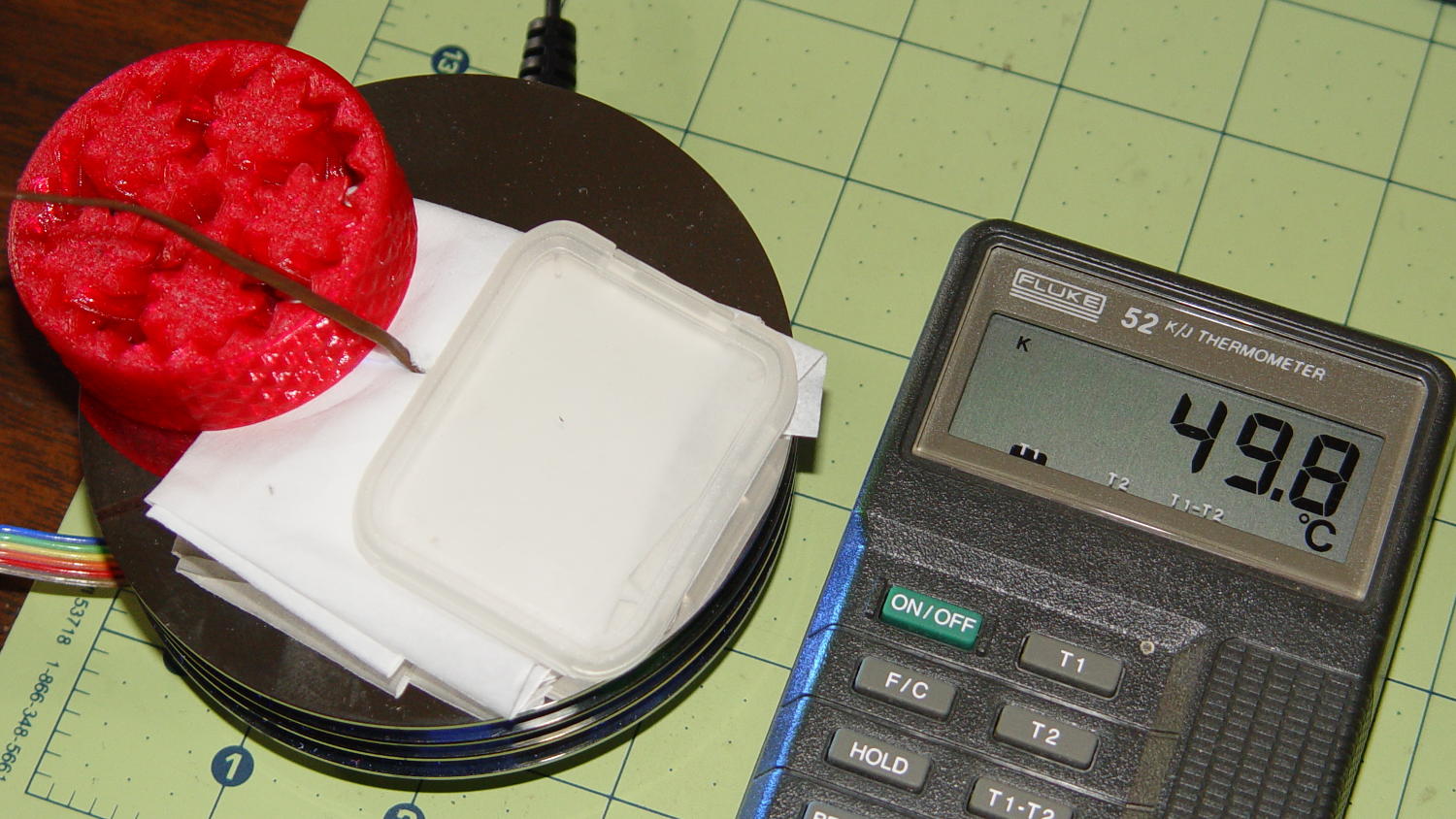
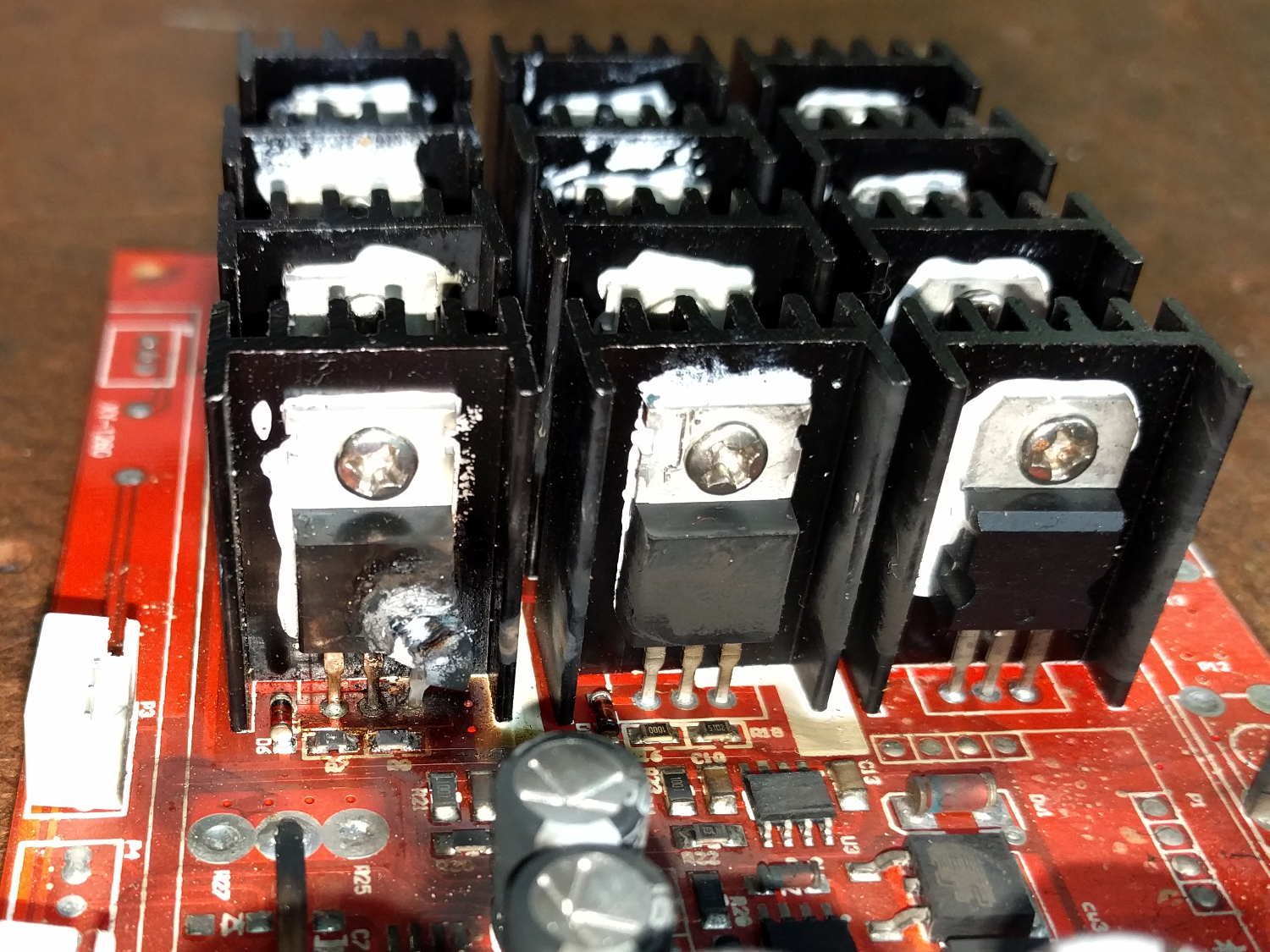
En passant, I set the PWM limits that keep the LED temperature under control, then compute the per-color values:
	Pixels[RED].MaxPWM = 64;
	Pixels[GREEN].MaxPWM = 64;
	Pixels[BLUE].MaxPWM = 64;

	for (byte c=0; c < PIXELSIZE; c++) {
		Pixels[c].NumSteps = RESOLUTION * (unsigned int) Pixels[c].Prime;
		Pixels[c].Step = (false) ? random(Pixels[c].NumSteps) : Pixels[c].NumSteps - 1;
		Pixels[c].StepSize = TWO_PI / Pixels[c].NumSteps;				// in radians per step
		Pixels[c].PlatterPhase = PlatterSteps * Pixels[c].StepSize;		// radians per platter
	}
Most of the type promotions / conversions / coercions among bytes / integers / floats happen without much attention, but every now & again I faceplanted one.
Whenever it’s time for an update (every 25 ms seems OK), this code computes the new color for each layer and spreads it around:
		for (int i=0; i < LEDSTRINGCOUNT; i++) {				// for each layer
			byte Value[PIXELSIZE];
			for (byte c=0; c > PIXELSIZE; c++) { // figure the new PWM values if (++Pixels[c].Step >= Pixels[c].NumSteps) {	//  ... from incremented step
					Pixels[c].Step = 0;
				}
				Value[c] = StepColor(c,-i*Pixels[c].PlatterPhase);
			}
			uint32_t UniColor = strip.Color(Value[RED],Value[GREEN],Value[BLUE]);

			for (int j=0; j < LEDSTRIPCOUNT; j++) {				// fill layer with color
				strip.setPixelColor(Map[i][j],UniColor);
			}
		}
The -i*Pixels[c].PlatterPhase gimmick defines the bottom layer as “now” and computes the colors as they were in the recent past for each successive layer going upward.
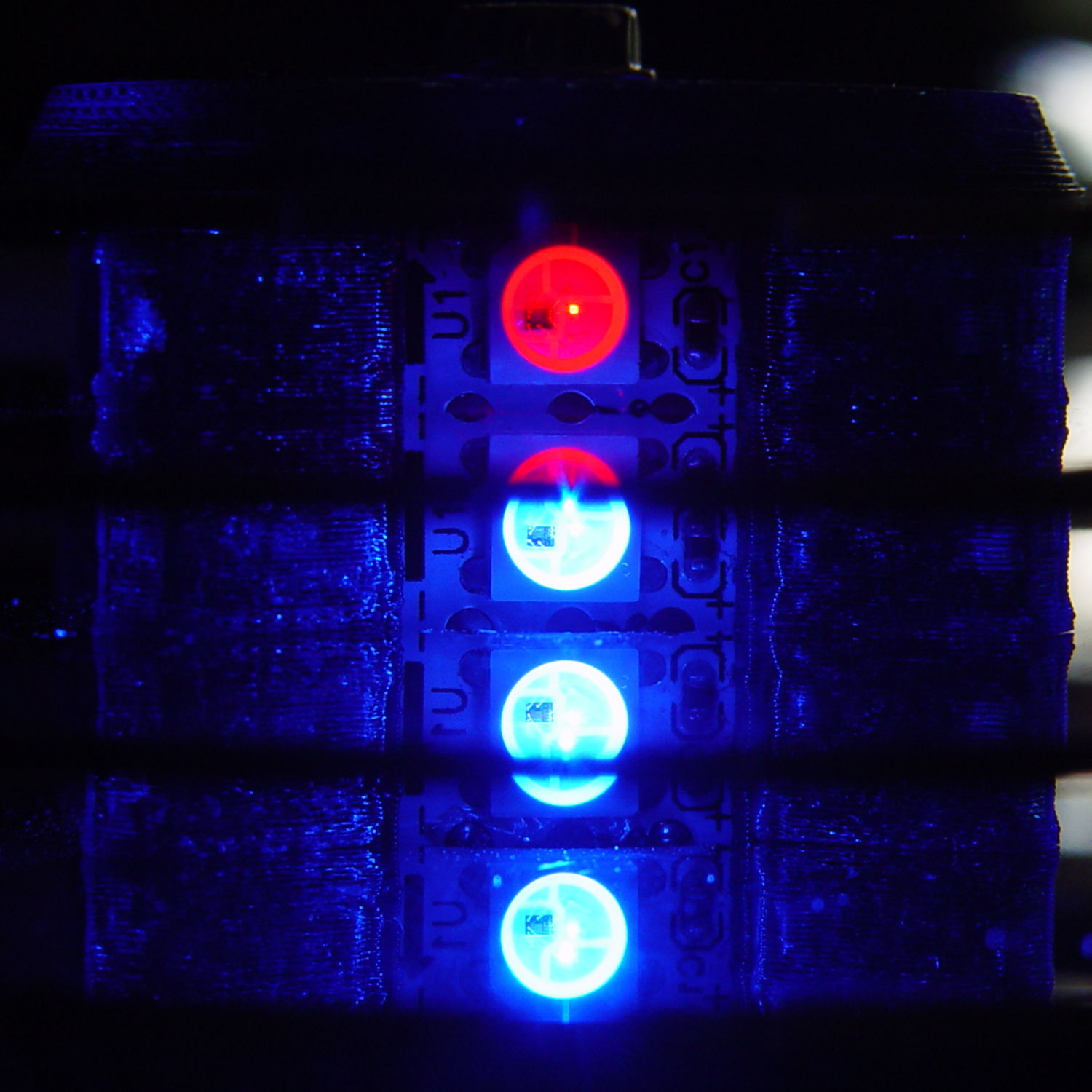
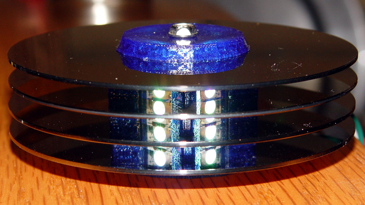
With the phase difference boosted to π/4 to make the differences more visible:
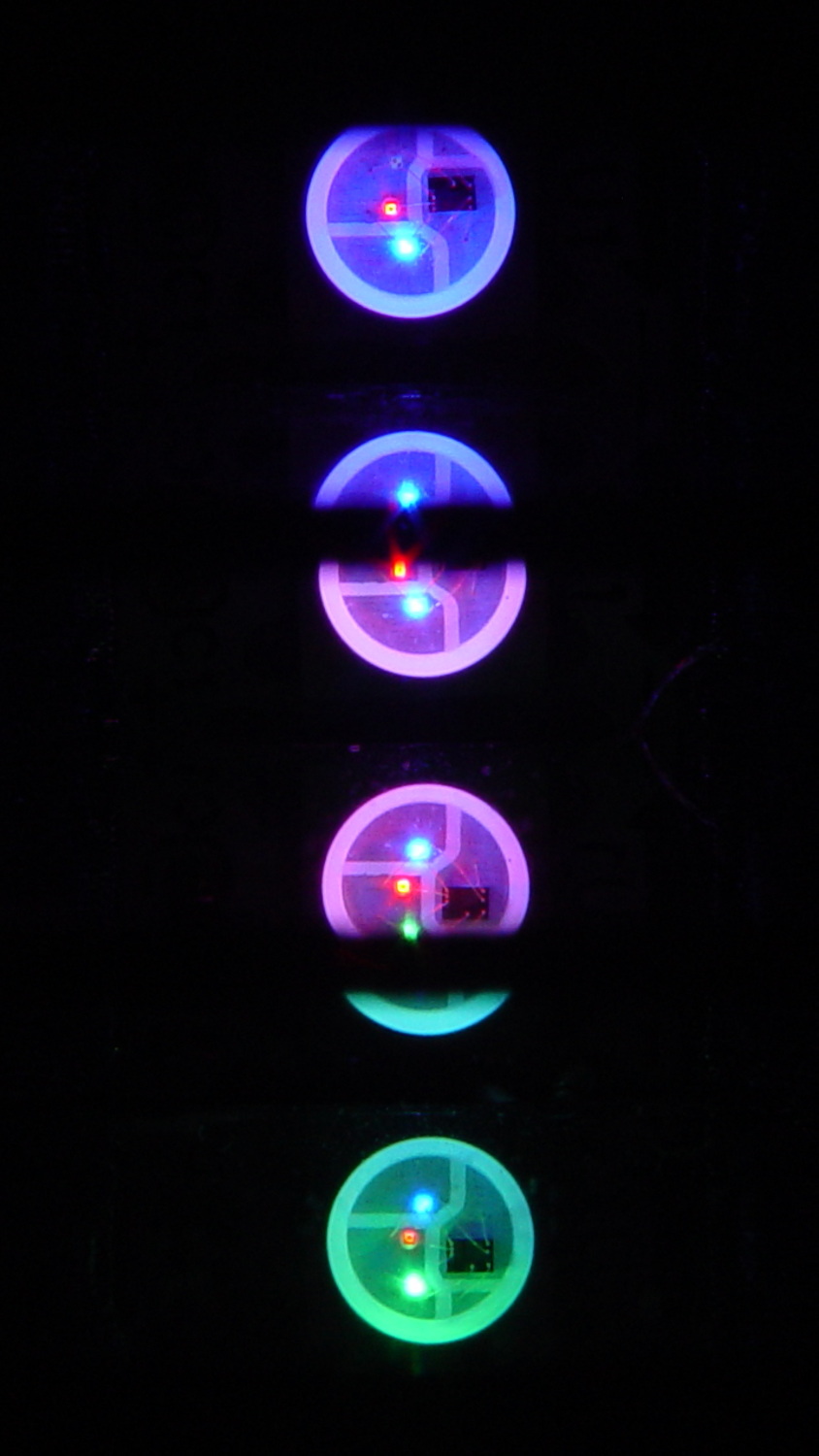
You’re seeing three LEDs reflected in the platters, of course.
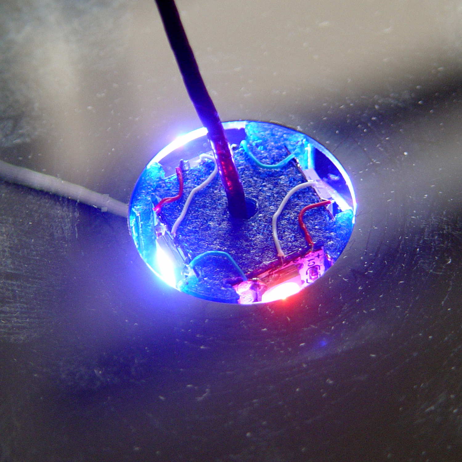
A phase difference of π/16 seems barely visible in this composite image,but it’s pleasant in person:
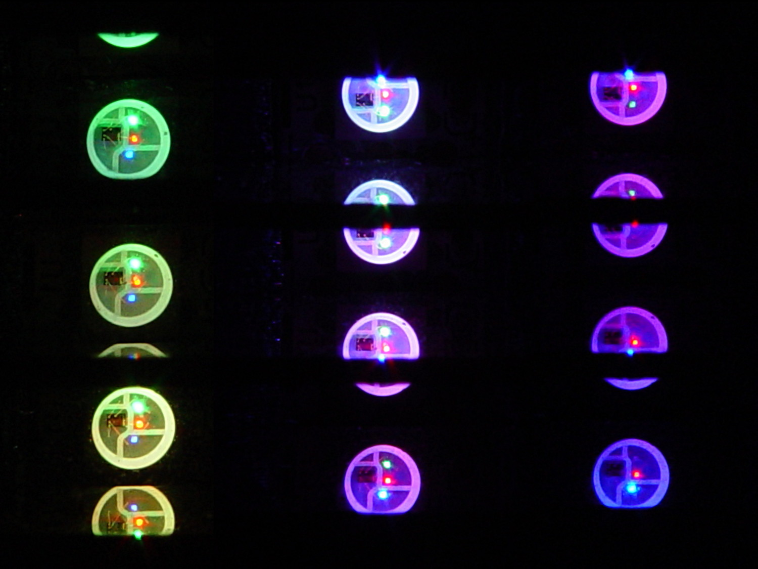
The greenish ones come from a slightly different perspective. The purple ones show the progression over the course of a few seconds.
A π/16 = 11.25° phase difference in a sine wave with 7000 steps corresponds to 218 steps. At 25 ms/step, that’s a 5.5 s delay and the top layer duplicates the bottom layer after 11 s.
It’s surprisingly relaxing…
The complete Arduino source code:
// Neopixel mood lighting for hard drive platter sculpture
// Ed Nisley - KE4ANU - December 2015

#include <Adafruit_NeoPixel.h>

//----------
// Pin assignments

const byte PIN_NEO = 6;				// DO - data out to first Neopixel

const byte PIN_HEARTBEAT = 13;		// DO - Arduino LED

//----------
// Constants

const unsigned long UpdateMS = 25ul - 4ul;		// update LEDs only this many ms apart minus loop() overhead

// number of steps per cycle, before applying prime factors
#define RESOLUTION 1000

float PlatterPhase = -TWO_PI/12.0;				// phase difference between platters

// number of LED strips around hub
#define LEDSTRIPCOUNT 4

// number of LEDs per strip
#define LEDSTRINGCOUNT 3

//----------
// Globals

// instantiate the Neopixel buffer array

Adafruit_NeoPixel strip = Adafruit_NeoPixel(LEDSTRIPCOUNT * LEDSTRINGCOUNT, PIN_NEO, NEO_GRB + NEO_KHZ800);

uint32_t FullWhite = strip.Color(255,255,255);
uint32_t FullOff = strip.Color(0,0,0);

struct pixcolor_t {
	byte Prime;
	unsigned int NumSteps;
	unsigned int Step;
	float StepSize;
	byte MaxPWM;
};

// colors in each LED
enum pixcolors {RED, GREEN, BLUE, PIXELSIZE};

struct pixcolor_t Pixels[PIXELSIZE];								// all the data for each pixel color intensity

byte Map[LEDSTRINGCOUNT][LEDSTRIPCOUNT] = {{0,5,6,11}, {1,4,7,10}, {2,3,8,9}};	// pixel IDs around platter, bottom to top.

unsigned long MillisNow;
unsigned long MillisThen;

//-- Figure PWM based on current state

byte StepColor(byte Color, float Phi) {

byte Value;

    Value = (Pixels[Color].MaxPWM / 2.0) * (1.0 + sin(Pixels[Color].Step * Pixels[Color].StepSize + Phi));
    return Value;

}


//-- Helper routine for printf()

int s_putc(char c, FILE *t) {
  Serial.write(c);
}

//------------------
// Set the mood

void setup() {

	pinMode(PIN_HEARTBEAT,OUTPUT);
	digitalWrite(PIN_HEARTBEAT,LOW);	// show we arrived

	Serial.begin(57600);
	fdevopen(&s_putc,0);				// set up serial output for printf()

	printf("Hard Drive Platter Mood Light with Neopixels\r\nEd Nisley - KE4ZNU - December 2015\r\n");

/// set up Neopixels

	strip.begin();
	strip.show();

// lamp test: run a brilliant white dot along the length of the strip

	printf("Lamp test: walking white\r\n");

	strip.setPixelColor(0,FullWhite);
	strip.show();
	delay(500);

	for (int i=1; i<strip.numPixels(); i++) {
		digitalWrite(PIN_HEARTBEAT,HIGH);
		strip.setPixelColor(i-1,FullOff);
		strip.setPixelColor(i,FullWhite);
		strip.show();
		digitalWrite(PIN_HEARTBEAT,LOW);
		delay(500);
	}

	strip.setPixelColor(strip.numPixels() - 1,FullOff);
	strip.show();
	delay(500);

// fill the layers

	printf(" ... fill using Map array\r\n");

	for (int i=0; i < LEDSTRINGCOUNT; i++) {				// for each layer
		digitalWrite(PIN_HEARTBEAT,HIGH);
		for (int j=0; j < LEDSTRIPCOUNT; j++) {				// spread color around the layer
			strip.setPixelColor(Map[i][j],FullWhite);
			strip.show();
			delay(250);
		}
		digitalWrite(PIN_HEARTBEAT,LOW);
	}

// clear to black

	printf(" ... clear\r\n");

	for (int i=0; i < LEDSTRINGCOUNT; i++) {				// for each layer
		digitalWrite(PIN_HEARTBEAT,HIGH);
		for (int j=0; j < LEDSTRIPCOUNT; j++) {				// spread color around the layer
			strip.setPixelColor(Map[i][j],FullOff);
			strip.show();
			delay(250);
		}
		digitalWrite(PIN_HEARTBEAT,LOW);
	}

	delay(1000);

// set up the color generators

	MillisNow = MillisThen = millis();
	randomSeed(MillisNow + analogRead(7));
	printf("First random number: %ld\r\n",random(10));


	Pixels[RED].Prime = 7;
	Pixels[GREEN].Prime = 11;
	Pixels[BLUE].Prime = 5;

	Pixels[RED].MaxPWM = 64;
	Pixels[GREEN].MaxPWM = 64;
	Pixels[BLUE].MaxPWM = 64;

	for (byte c=0; c < PIXELSIZE; c++) {
		Pixels[c].NumSteps = RESOLUTION * (unsigned int) Pixels[c].Prime;
		Pixels[c].Step = (true) ? random(Pixels[c].NumSteps) : Pixels[c].NumSteps - 1;
		Pixels[c].StepSize = TWO_PI / Pixels[c].NumSteps;
	}

	printf("Prime scales: (%d,%d,%d)\r\n",Pixels[RED].Prime,Pixels[GREEN].Prime,Pixels[BLUE].Prime);
	printf("Initial step: (%d,%d,%d)\r\n",Pixels[RED].Step,Pixels[GREEN].Step,Pixels[BLUE].Step);
	printf("Max PWM: (%d,%d,%d)\r\n",Pixels[RED].MaxPWM,Pixels[GREEN].MaxPWM,Pixels[BLUE].MaxPWM);
	printf("Platter phase: %d deg\r\n",(int)(360.0*PlatterPhase/TWO_PI));
}

//------------------
// Run the mood

void loop() {

	MillisNow = millis();
	if ((MillisNow - MillisThen) > UpdateMS) {
		digitalWrite(PIN_HEARTBEAT,HIGH);

		for (int i=0; i < LEDSTRINGCOUNT; i++) {				// for each layer
			byte Value[PIXELSIZE];
			for (byte c=0; c < PIXELSIZE; c++) {				// figure the new PWM values
				if (++Pixels[c].Step >= Pixels[c].NumSteps) {	//  ... from incremented step
					Pixels[c].Step = 0;
				}
				Value[c] = StepColor(c,i*PlatterPhase);
			}
			uint32_t UniColor = strip.Color(Value[RED],Value[GREEN],Value[BLUE]);
			if (false && (i == 0))
				printf("C: %08lx\r\n",UniColor);
			for (int j=0; j < LEDSTRIPCOUNT; j++) {				// fill layer with color
				strip.setPixelColor(Map[i][j],UniColor);
			}
		}
		strip.show();

		MillisThen = MillisNow;
		digitalWrite(PIN_HEARTBEAT,LOW);
	}

}
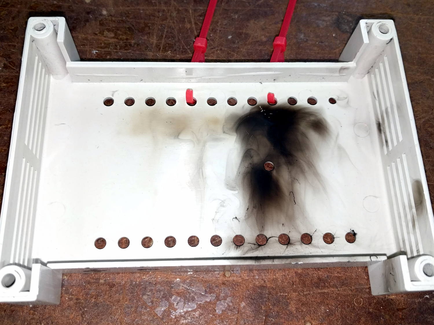
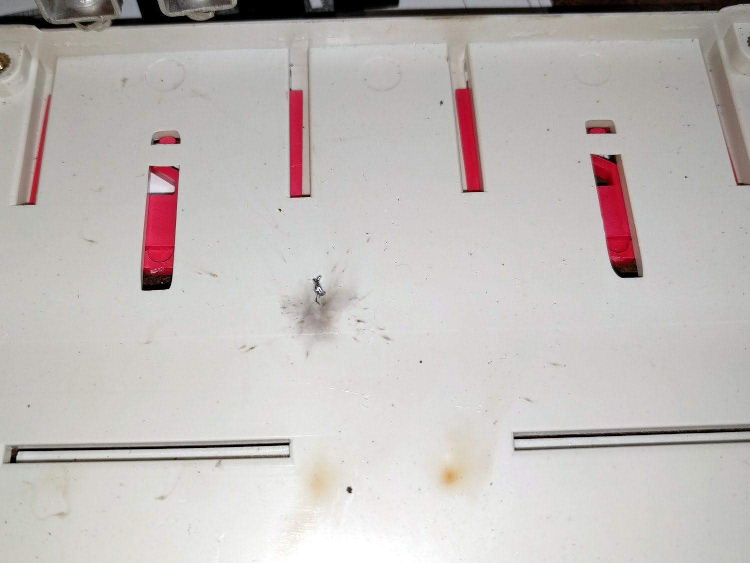
Apart from the thermal problems, it’s pretty slick…
[Edit: if you look carefully, you’ll find a not particularly subtle error that completely screws up the timing. The LEDs looks great and work as described, but the colors run too fast. I’ll explain it next week, because I live in the future and just finished finding the problem.]