The Smell of Molten Projects in the Morning

Ed Nisley's Blog: Shop notes, electronics, firmware, machinery, 3D printing, laser cuttery, and curiosities. Contents: 100% human thinking, 0% AI slop.

Category: Electronics Workbench

Electrical & Electronic gadgets

  • LF Loop Antenna: GPS Frequency Check

    I stuck some old 12 V 7 A·h batteries in my homebrew power supply for the HP 3801A GPS Time / Frequency Standard, fired it up, put the antenna where it could see a good chunk of the sky, gave it a day to warm up / settle out, and it’s perfectly happy:

    ------------------------------- Receiver Status -------------------------------
    
    SYNCHRONIZATION ............................................. [ Outputs Valid ]
    SmartClock Mode ___________________________   Reference Outputs _______________
    >> Locked to GPS                              TFOM     3             FFOM     0
       Recovery                                   1PPS TI -38.3 ns relative to GPS
       Holdover                                   HOLD THR 1.000 us
       Power-up                                   Holdover Uncertainty ____________
                                                  Predict  366.2 us/initial 24 hrs
    
    ACQUISITION ............................................ [ GPS 1PPS CLK Valid ]
    Satellite Status __________________________   Time _____ +1 leap second pending
    Tracking: 4        Not Tracking: 6            UTC      18:22:19     22 Jul 2016
    PRN  El  Az   SS   PRN  El  Az                1PPS CLK Synchronized to UTC
      3  34 104   48   * 1  36  48                ANT DLY  0 ns
     17  62 308  103     6  27 220                Position ________________________
     19  39 281   50    11  21  58                MODE     Hold
     28  80 133   64   *22  Acq .
                        24  12 319                LAT      N  41:39:32.328
                        30  15 191                LON      W  73:52:26.733
    ELEV MASK 10 deg   *attempting to track       HGT               +82.87 m  (MSL)
    HEALTH MONITOR ......................................................... [ OK ]
    Self Test: OK    Int Pwr: OK   Oven Pwr: OK   OCXO: OK   EFC: OK   GPS Rcv: OK
    scpi >
    

    The FFOM 0 entry says the Frequency Figure Of Merit is “within specifications” of 10-9, averaged over one day. That means the actual frequency should be within 0.010 Hz of 10 MHz.

    Feeding the 10 MHz frequency reference into the (equally warmed up) HP 8591E spectrum analyzer and selecting an absurdly narrow span produces a comforting sight:

    HP Z2801A GPS Receiver - 10 MHz ref - HP 8591E
    HP Z2801A GPS Receiver – 10 MHz ref – HP 8591E

    Given the horizontal resolution, that’s dead on 10 MHz.

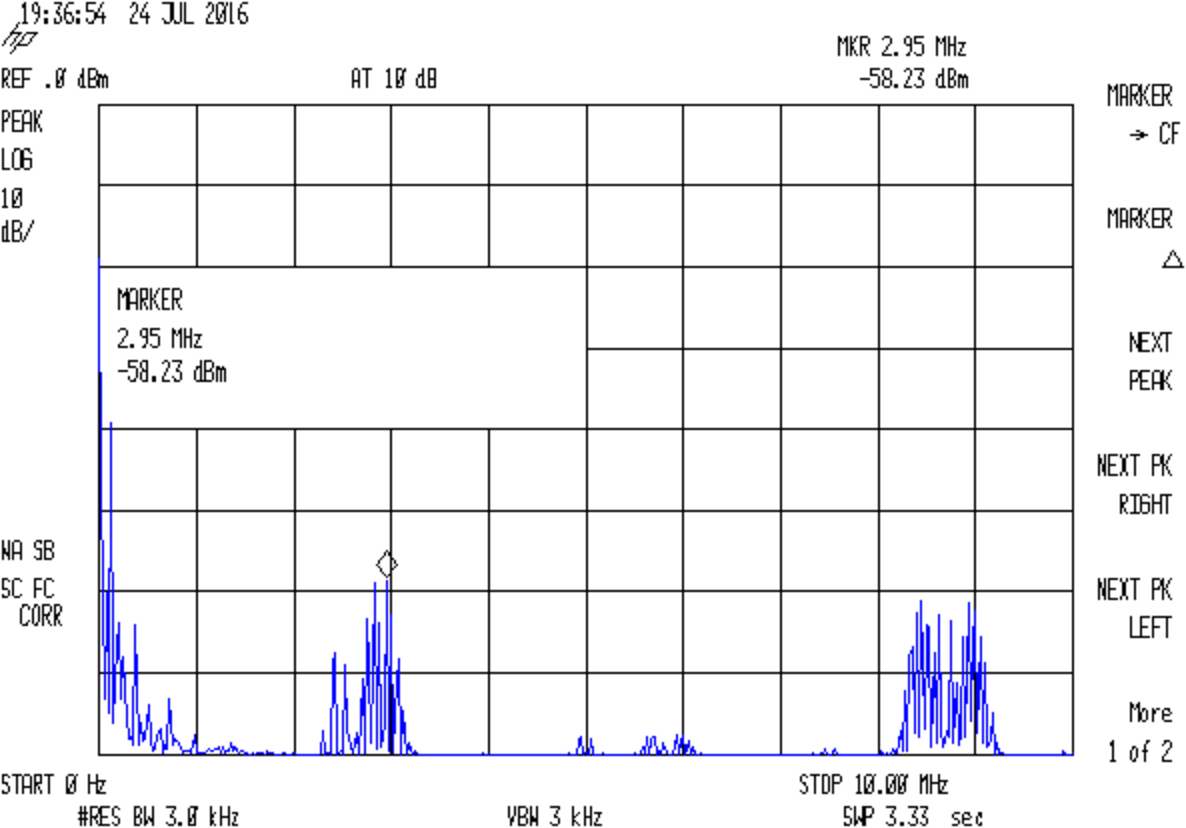
    So, yeah, that signal at 57-ish kHz really isn’t at 60.000 kHz:

    Loop - 40T 1nF - spectrum
    Loop – 40T 1nF – spectrum

    Which is good to know …

  • External Li-Ion Pack: More Sawing

    Two of the external Li-Ion battery packs I’m using with the bike radios seemed to fail quickly after being charged, so I sawed them open to check the state of the cells. This time I used the fine-tooth cutoff blades, rather than a coarse slitting saw:

    Li-Ion pack - sawing case
    Li-Ion pack – sawing case

    As before, a 2 mm depth-of-cut, done 0.25 mm per pass after the first millimeter, seems about right. I didn’t saw the front of the case near the jack, which proved to be a mistake; the interlocked case halves need cutting.

    No cell trouble found, which leads me to suspect an intermittent short in the battery-to-radio cable that trips the battery protection circuit. The spare cables went into hiding during the shop cleanout, so I can’t swap in a known-good cable just yet; of course, the existing cable behaves perfectly on the bench. The suspect cable is now on my bike and, if the problem follows the cable, further surgery will be in order.

    For the record, the insides look like this:

    Li-Ion pack - interior
    Li-Ion pack – interior

    The cell label seems to show a 2004 date code:

    Li-Ion pack - cell label
    Li-Ion pack – cell label

    Given that I got them on closeout in early 2010, it definitely isn’t 2014.

    Unlike some of the other cheap batteries around here, they’ve been spectacularly successful!

  • LF Loop Antenna: 60 kHz Tuning

    The object of soldering all 40 wires in the 5 m hank of ribbon cable  in series is to build a 40 turn loop antenna to receive LF radio signals like WWVB at 60 kHz. The antenna, being basically a big coil of wire, will have an inductance that depends on its layout, so putting a capacitor in parallel turns it into a resonant tank circuit. Given a particular layout (and, thus, an inductance), you can choose the capacitor to make the antenna resonant at whatever frequency you need (within reason).

    With the joints soldered & reinforced with epoxy, the inductance across all 40 turns:

    • 535 µH – rolled into a compact bundle
    • 6.66 mH – vaguely circular loop on the concrete floor
    • 5.50 mH – lumpy rectangle on the concrete floor

    Back in a slightly different circular layout on the floor:

    • 6.8 mH – across all 40 turns, as above
    • 2.0 mH – across either set of 20 turns from the center tap

    Given that inductance varies as the square of the number of turns, you’d expect a factor of four between those two inductances, but that’s not how it worked out.

    Hanging the loop from a pair of screws in the floor joists to make a droopy rectangle-oid shape and driving it from a 600 Ω signal generator through a 10 kΩ resistor, it’s self-resonant at 213 kHz. Repeating that with a 470 kΩ resistor drops the resonance to 210 kHz, which isn’t different enough to notice and surely has more to do with my moving the loop while dinking with resistors.

    Adding parallel capacitance (measured with an LCR meter, just to be sure) changes the resonance thusly:

    • 9.9 nF → 20 kHz
    • 900 pF → 64 kHz
    • 400 pF → 87 kHz
    • 250 pF → 108 kHz
    • none → 213 kHz

    Because the resonant frequency varies inversely as the square root of the capacitance, halving the resonant frequency means you’ve increased the capacitance by a factor of four. Because 250 pF halves the frequency (mostly kinda sorta close enough), the loop’s stray capacitance must be about 1/3 of that: 83 pF.

    Yeah, 1/3, not 1/4: the additional capacitance adds to the stray capacitance, so it goes from 83 pF to 250 + 83 pF = 333 pF, which is four times 83 pF.

    (If that sound familiar, it’s similar to the resonant snubber calculation.)

    The self-resonant frequency of 213 kHz and the 83 pF stray capacitance determines the loop inductance:

    L = 1/((2π · 213 kHz)^2 · 83 pF) = 6.9 mH

    Pretty close to the measured value from the floor, I’d say.

    To resonate the antenna at 60 kHz, the total capacitance must be:

    60 kHz = 1/(2π · sqrt(6.9 mH · C)) → C = 1050 pF

    Which means an additional 1050 – 83 =  970-ish pF should do the trick, which is about what you’d expect from the 64 kHz resonance with the 900 pF cap above. I paralleled pairs of caps until it resonated at 59.9 kHz.

    The -3 dB points (voltage = 1/sqrt(2) down from the peak) turned out to be 58.1 and 60.1 kHz, so my kludged caps are slightly too large or, once again, I nudged the loop.

    Figuring Q = (center frequency) / bandwidth = 59.1 / 2 = 30, which works out close enough to Q = X / R = 2600 / 80 = 33 to be satisfying. Using standard 26-ish AWG ribbon cable, rather than crappy 31-ish AWG eBay junk, would double the conductor area, halve the series resistance, and double the Q. Faced with that much resistance, I’m not sure better caps would make any difference.

    Attaching the spectrum analyzer through a 470 Ω resistor to reduce the load:

    Loop - 40T 1nF - spectrum
    Loop – 40T 1nF – spectrum

    I’d love to believe that big peak over on the left at 57.1 kHz is WWVB, but it’s not.

    What’s more important: the broad hump between 56 and 62 kHz, where the increased amount of background hash suggests the antenna really is resonant, with a center frequency around 59 kHz. The -3 dB points might be 57 and 61 kHz, but at 10 dB/div with 5 dB of hash, I’d be kidding myself.

    Dang, I love it when the numbers work out!

    It’s faintly possible the spectrum analyzer calibration is off by 2.5 kHz at the low end of its range. The internal 300 MHz reference shows 299.999925 and it puts FM stations where they should be, but the former could be self-referential error and the latter lacks enough resolution to be comforting. I must fire up the GPS frequency reference, let it settle for a few days, see whether it produces 10.000000 MHz like it should, then try again.

    The original measurements:

    Loop antenna tuning - measurements
    Loop antenna tuning – measurements
  • LF Loop Antenna: Joint Soldering

    Given five meters of 40 conductor ribbon cable, the object is to make a 40 turn five foot diameter loop antenna by soldering the ends together with a slight offset. After squaring off, marking, and taping the cable ends, I stripped the wires:

    LF Loop Antenna - wire stripping
    LF Loop Antenna – wire stripping

    Twirling those little snippets before pulling them off produced nicely twisted wire ends with no few loose strands. Separate the individual wires, wrap with transformer tape to prevent further separation, run a flux pen along the wire ends, tin with solder, repeat on the far end of the cable.

    Tape one end to the ceramic tile. Align the other end with a one-wire lateral offset and the stripped sections overlapping, then tape it down. Slide a paper strip between the ends, passing under every other wire, to separate the top pairs from the bottom pairs, then tape the strip in place:

    LF Loop Antenna - wire prep
    LF Loop Antenna – wire prep

    Grab each left wire with a needle point tweezer, forcibly align with the corresponding right wire, touch with the iron, iterate:

    LF Loop Antenna - top solder joints
    LF Loop Antenna – top solder joints

    The red wire trailing off to the left will become the center tap.

    Slide a strip of the obligatory Kapton tape underneath the finished joints, slobber on enough clear epoxy to bond the insulation on both sides of the joints into a solid mass, squish another strip atop the epoxy, smooth down, wait for curing.

    Untape from the tile, flip, re-tape, solder the bottom joints similarly, add Kapton / epoxy / Kapton, and that’s that:

    LF Loop Antenna - complete joint
    LF Loop Antenna – complete joint

    Prudence dictates checking for end-to-end continuity after you finish soldering and before you do the Kapton + epoxy thing, which is where I discovered I had 80 Ω of distributed resistance along 200 meters of cable. A quick check showed 40 Ω at the center tap and 20 Ω at the quarters (the black wires on the left mark those points), so it wasn’t a really crappy joint somewhere in the middle.

    The joint and its dangly wires cry out for a 3D printed stiffener which shall remain on the to-do list until I see how the loop tunes up.

  • eBay Listings: Read Carefullly

    What’s wrong with this picture? (clicky for more dots)

    eBay - 40 pin IDC cable - header
    eBay – 40 pin IDC cable – header

    Not obvious?

    Here’s the description, slightly reformatted for clarity:

    New 5m IDC Standard 40 WAY 1.8” Multi-Color Flat Ribbon Cable Wire Connector

    Description

    Type: IDC standard.

    10 colors, 4 group, total 40 pcs cables per lot

    5 meter per lot.

    width: 4.7 cm / 1.8 inch

    Package content: 5M Flat Color Ribbon Cable

    If you divide the 1.8 inch cable width by its 40 conductors, you find the wires lie on a 45 mil pitch. If you were expecting this “IDC standard” cable to fit in standard insulation displacement cable connectors with a 50 mil pitch, you’d be sorely disappointed. You can get metric ribbon cable with a 1 mm = 39 mil pitch, but this ain’t that, either.

    Here’s what an individual eBay wire (black jacket) looks like, compared to a wire from a standard ribbon cable (red jacket):

    Ribbon cable - 26 AWG - eBay vs standard
    Ribbon cable – 26 AWG – eBay vs standard

    A closer look at the strands making up the wires:

    Ribbon cable - 26 AWG - eBay vs standard - strands
    Ribbon cable – 26 AWG – eBay vs standard – strands

    As nearly as I can measure with my trusty caliper, the eBay ribbon cable has wire slightly smaller than 30 AWG, made up of seven 40 AWG strands, as opposed to standard 26 AWG wire made of seven 34 AWG strands. The good stuff might be 28 AWG / 7×36 AWG, but I was unwilling to break out the micrometer for more resolution.

    I’d like to say I noticed that before buying the cable, but it came to light when I measured the total resistance of the whole cable: 80 Ω seemed rather high for 200 meters of 26 AWG wire. The wire tables say that’s about right for 31 AWG copper, though.

    Changing the AWG number by three changes the conductor area by a factor of two, so you’re getting less than half the copper you expected. Bonus: it won’t fit any IDC connectors you have on the shelf, either.

    Turns out a recent QEX article suggested building an LF loop antenna from a ribbon cable, so I was soldering all the conductors in series, rather than using connectors, and it should work reasonably well despite its higher DC resistance.


  • Kenmore Model 158 Power Switch: Laying-on-of-hands Repair

    The power switch on Mary’s “embroidery” Kenmore Model 158 sewing machine became exceedingly stiff, to the extent she said it was painful to push. Buying a shiny new switch seemed iffy, because a cursory search through the usual reputable electronic suppliers suggested there’s no way to specify how stiff the button might be, nor how that might feel in actual practice.

    The switch harvested from the pulse-drive machine felt somewhat less stiff, so I decided to (try to) loosen it up and, if that worked, swap it for the stubborn one.

    A pair of rivets hold the two halves of the switch together, obviously intended as a permanent solution. A carbide burr in the Dremel tool dealt with them easily enough:

    Model 158 Power Switch - grinding rivets
    Model 158 Power Switch – grinding rivets

    Inside, the actuator drives a rotating brass contact:

    Model 158 Power Switch - rotor
    Model 158 Power Switch – rotor

    Two stationary brass contacts are spot-welded to the wires:

    Model 158 Power Switch - contacts
    Model 158 Power Switch – contacts

    The actuator under the button consists of a helix-twisted steel rod, a rather stiff spring, and a four-vaned phenolic blade that engages those two little flaps on the rotor. The rivet holes exactly fit plain old 1-72 screws:

    Model 158 Power Switch - actuator stem
    Model 158 Power Switch – actuator stem

    Not seeing anything obviously fix-able inside, I wiped the excess oil off and reassembled it in reverse order:

    Model 158 Power Switch - reassembled
    Model 158 Power Switch – reassembled

    Astonishingly, that bit of attention loosened it up: the button now presses easily!

    I swapped it with the too-stiff switch and declared victory…

  • Vacuum Tube LEDs: Brass Ersatz Heatsink

    A chunk of 1/2 inch = 12.7 mm brass hex rod looks pretty good as an ersatz heatsink serving as an ersatz plate cap on a halogen bulb standing in for a vacuum tube:

    Halogen bulb brass cap - overview
    Halogen bulb brass cap – overview

    The knockoff Neopixels measure just over 10 mm at their widest points, but some judicious filing rounded it off and brought it down to fit in the 3/8 inch = 0.375 = 9.52 mm hole I drilled in the hex:

    Halogen bulb brass cap - wiring
    Halogen bulb brass cap – wiring

    I let it run for a day like that to make sure the thing wasn’t going to crap out, then epoxied everything in place. If the WS2812B controller fails, the repair will require drilling out all the electronics and wiring, then rebuilding it in place.

    The fins come from the same HSS cutoff tool I used for the Bowl o’ Fire cap, cut at 2.5 mm intervals to produce 0.9 mm fins that IMO better suit the smaller diameter. I stopped cutting when the tool got through the hex flats to produce a continuous ring, cut the hex off a bit above the top fin, rounded the end with a carbide insert cutting tool, then sanded the flats to shine ’em up a bit:

    Halogen bulb brass cap - detail flash
    Halogen bulb brass cap – detail flash

    It turns out that 12 inches of wire inside PET braid barely reaches from the cap to the Arduino Pro Mini in the base:

    Halogen bulb brass cap - Arduino Pro Mini
    Halogen bulb brass cap – Arduino Pro Mini

    Next time, I’m going to add half a foot more wire than I think it can possibly require, with PET braid to suit.

    A thin ring of clear epoxy holds the “heatsink” at the dead center of the bulb. It lights up a bit more than I expected, so opaque epoxy may be in order:

    Halogen bulb brass cap - detail red
    Halogen bulb brass cap – detail red

    It’s still too big to suit even the big 21HB5A tubes, but brass definitely wins over plastic!

    That blue PETG base has become the least-attractive part of the lamp, but it’s survivable for now.

    It runs the same TubeMood firmware as the Bowl o’ Fire.