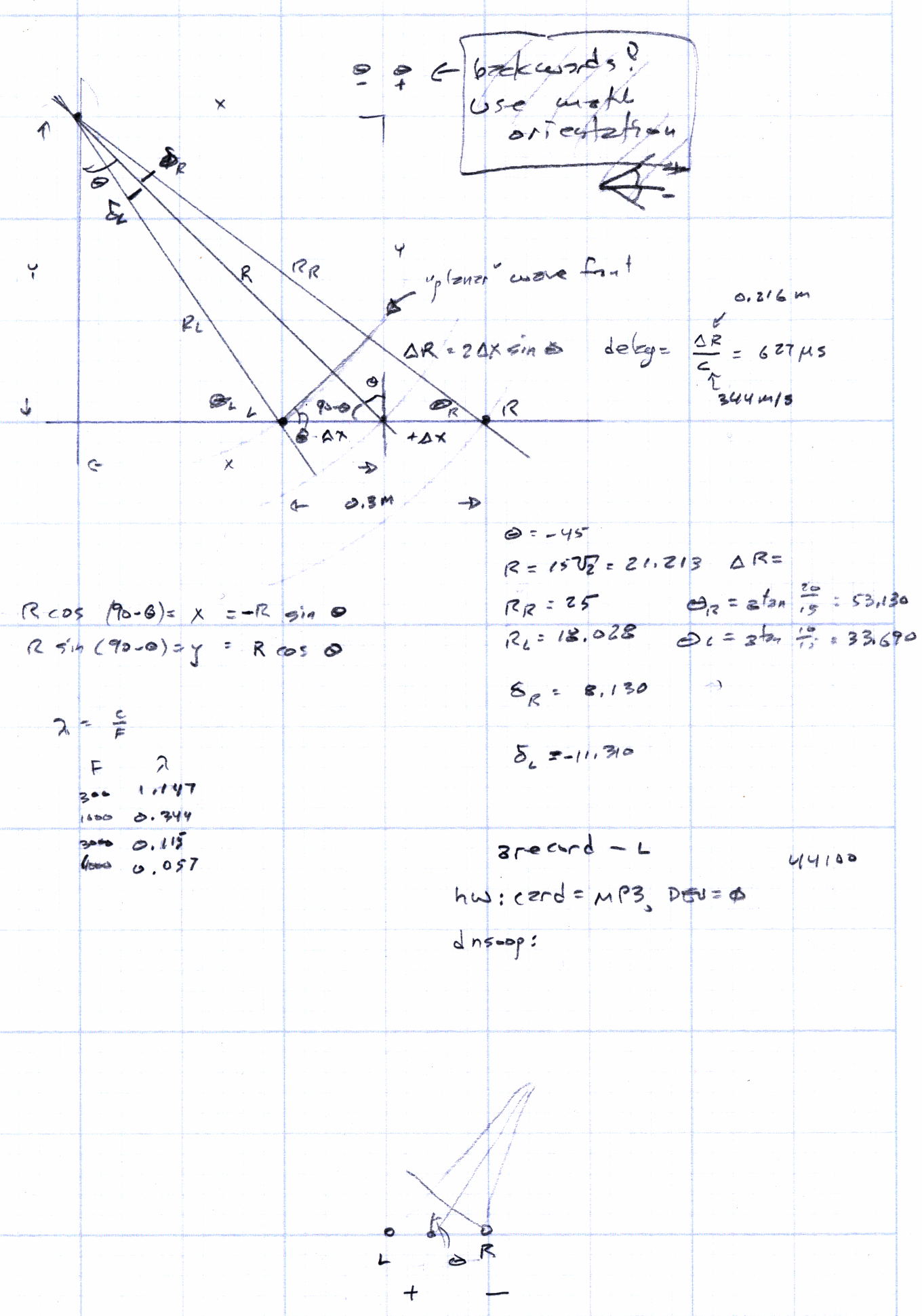
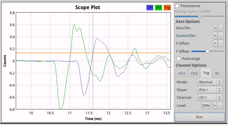
Given a point source of audio (or RF, for that matter) that’s far enough away to produce more-or-less plane wavefronts, the range difference between two microphones (or ears) is:
ΔR = (mic separation) x sin Θ
The angle lies between the perpendicular to the line from the midpoint between the mics counterclockwise to the source source: + for sounds to your left, – for sounds to your right. That’s the trig convention for angular measurement with 0° directly ahead, not the compass convention, but you can argue for either sign if you keep track of what’s going on.
The time delay between the mics, given c = speed of sound:
ΔT = ΔR / c
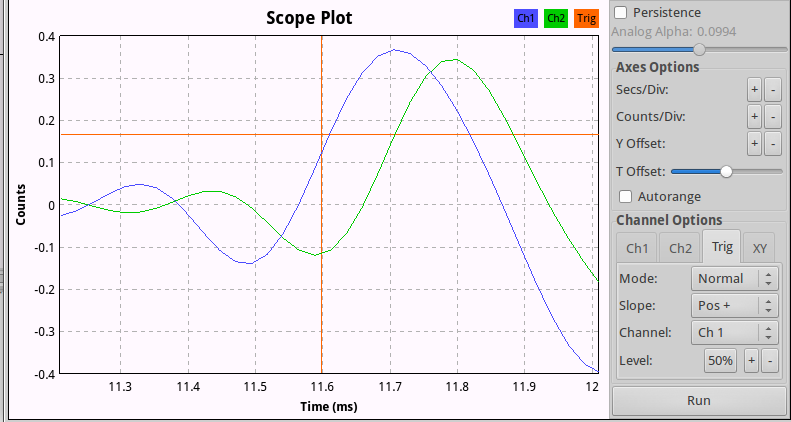
For microphones 300 mm apart and c = 344 m/s:
ΔT = 872 µs = 0.3 m / 344 m/s
If you delay the sound from the mic closest to the source by that amount, then add the mic signals, you get a monaural result that emphasizes, at least a little bit, sounds from that source in relation to all other sounds.
In principle, you could find the angle by listening for the loudest sound, but that’s a fool’s game.
There’s an obvious symmetry for a source on the same side, at the same angle, toward the rear.
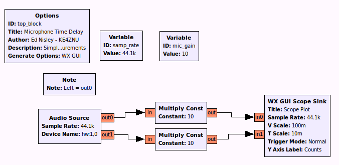
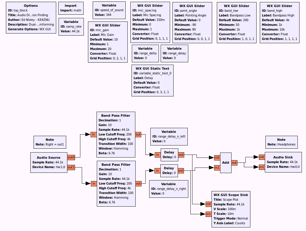
A GNU Radio data flow diagram that lets you set the angle and listen to / watch the results:
The original doodles show it takes me a while to work around to the answer: