What’s wrong with this picture? (clicky for more dots)
Not obvious?
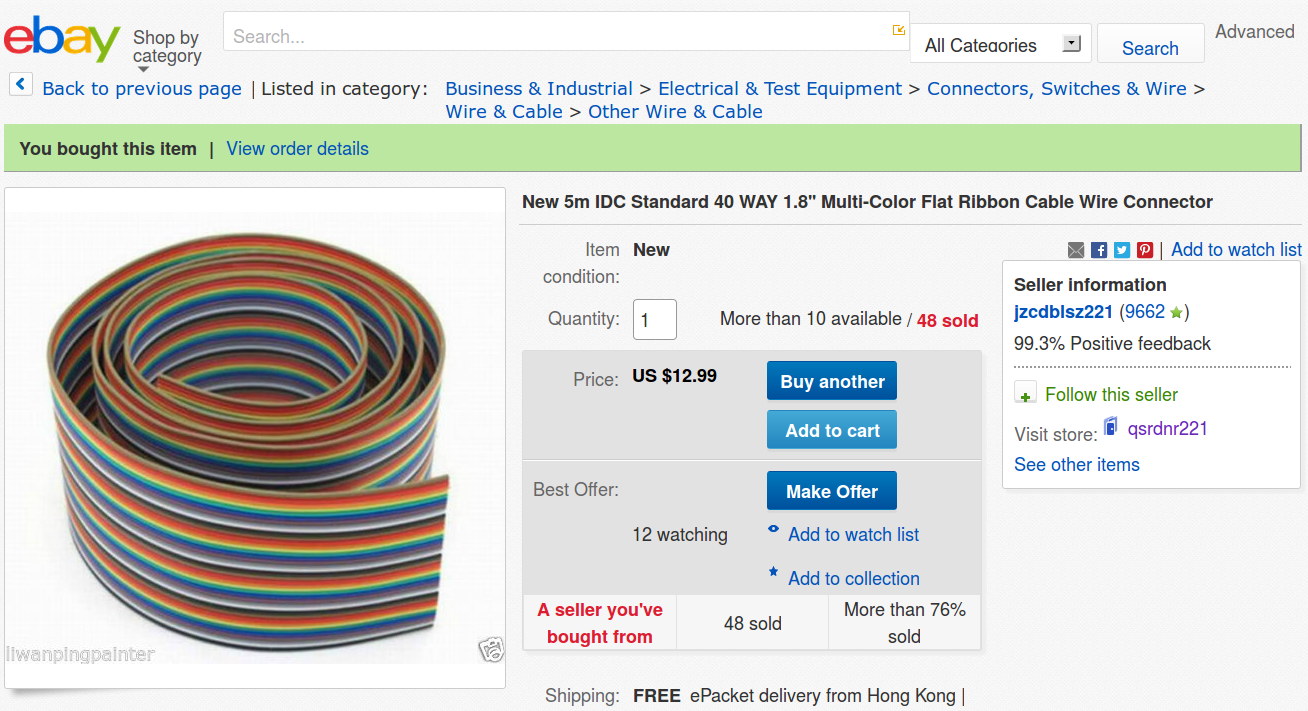
Here’s the description, slightly reformatted for clarity:
New 5m IDC Standard 40 WAY 1.8” Multi-Color Flat Ribbon Cable Wire Connector
Description
Type: IDC standard.
10 colors, 4 group, total 40 pcs cables per lot
5 meter per lot.
width: 4.7 cm / 1.8 inch
Package content: 5M Flat Color Ribbon Cable
If you divide the 1.8 inch cable width by its 40 conductors, you find the wires lie on a 45 mil pitch. If you were expecting this “IDC standard” cable to fit in standard insulation displacement cable connectors with a 50 mil pitch, you’d be sorely disappointed. You can get metric ribbon cable with a 1 mm = 39 mil pitch, but this ain’t that, either.
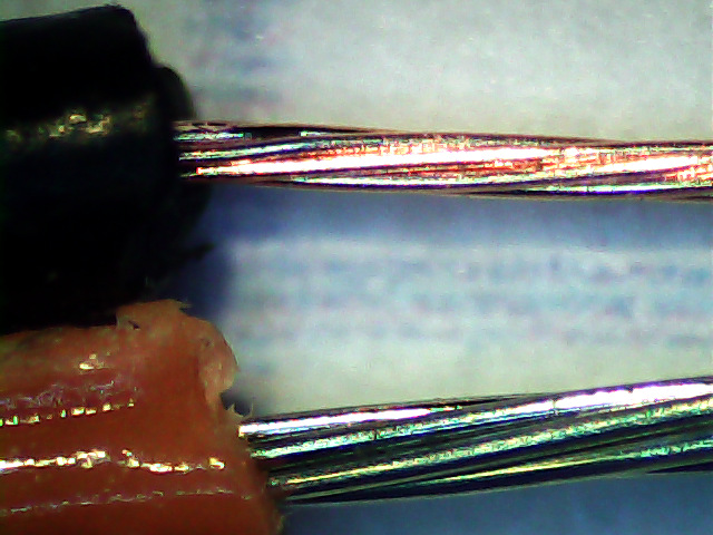
Here’s what an individual eBay wire (black jacket) looks like, compared to a wire from a standard ribbon cable (red jacket):
A closer look at the strands making up the wires:
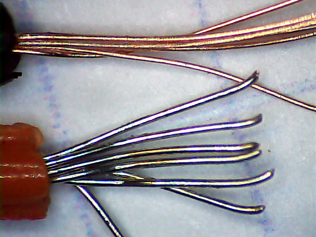
As nearly as I can measure with my trusty caliper, the eBay ribbon cable has wire slightly smaller than 30 AWG, made up of seven 40 AWG strands, as opposed to standard 26 AWG wire made of seven 34 AWG strands. The good stuff might be 28 AWG / 7×36 AWG, but I was unwilling to break out the micrometer for more resolution.
I’d like to say I noticed that before buying the cable, but it came to light when I measured the total resistance of the whole cable: 80 Ω seemed rather high for 200 meters of 26 AWG wire. The wire tables say that’s about right for 31 AWG copper, though.
Changing the AWG number by three changes the conductor area by a factor of two, so you’re getting less than half the copper you expected. Bonus: it won’t fit any IDC connectors you have on the shelf, either.
Turns out a recent QEX article suggested building an LF loop antenna from a ribbon cable, so I was soldering all the conductors in series, rather than using connectors, and it should work reasonably well despite its higher DC resistance.