Ed Nisley's Blog: Shop notes, electronics, firmware, machinery, 3D printing, laser cuttery, and curiosities. Contents: 100% human thinking, 0% AI slop.
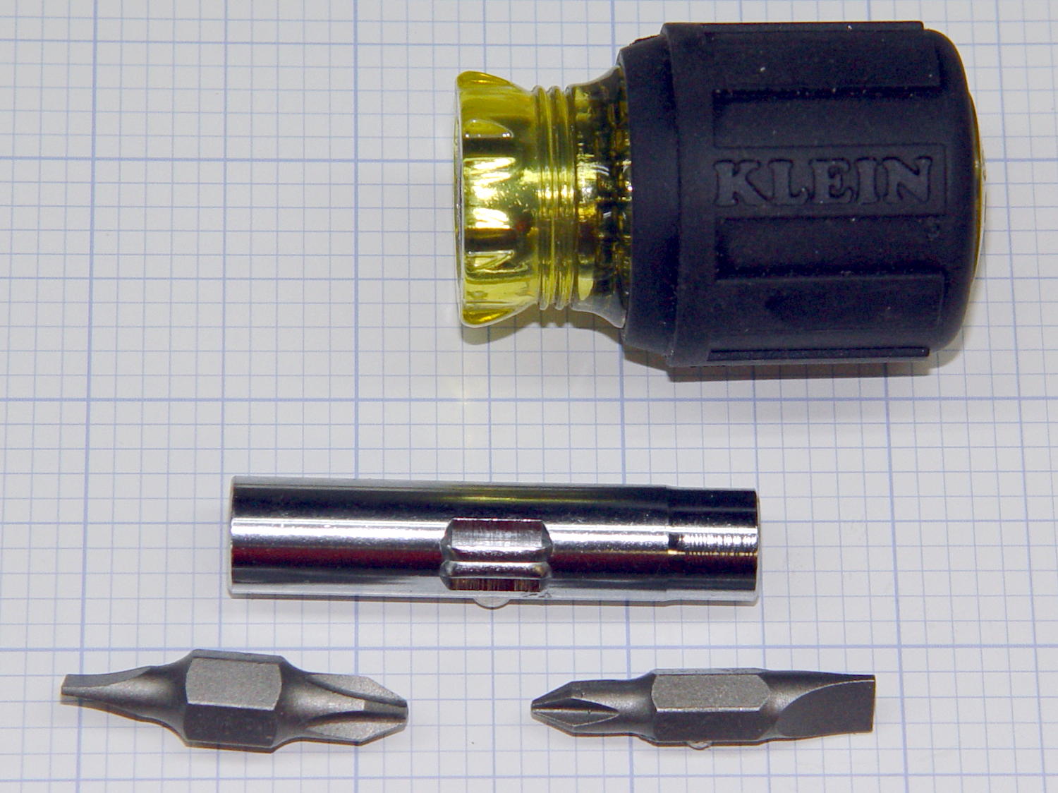
The steel shaft has a 1/4 inch hex socket on one end, a 5/16 hex socket on the other, the two hex bits handle the usual screws, and it’s smaller than it looks.
You must figure out what to do with the loose driver bit while using a socket.
No ratchet, but you won’t miss it.
Available from the usual online sources for about ten bucks; accept no substitutes…
Yeah, tanker boots and all; not the weirdest thing we saw during RIT’s graduation ceremonies.
This summer marks her fourth of four co-op semesters with Real Companies Doing Tech Stuff and her final classes end in December; RIT holds one ceremony in the spring and being offset by a semester apparently isn’t all that unusual. She (thinks she) has a job lined up after graduation and doesn’t need her doting father’s help.
But, hey, should you know someone with a way-cool opportunity (*) for a bright, fresh techie who’s increasingly able to build electronic & mechanical gadgets and make them work, drop me a note and I’ll put the two of you in touch. [grin]
(*) If that opportunity should involve 3D printed prosthetics with sensors and motors, she will crawl right out of your monitor…
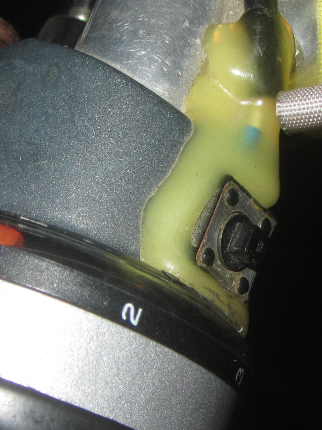
Long ago, Mary picked out a PTT switch with a raised, square post that provided a distinct shape and positive tactile feedback:
PTT Button – bare post
Time passes, she dinged her thumb in the garden, and asked for a more rounded button. I have some switches with rounded caps, but replacing the existing switch looked a lot like work, sooooo:
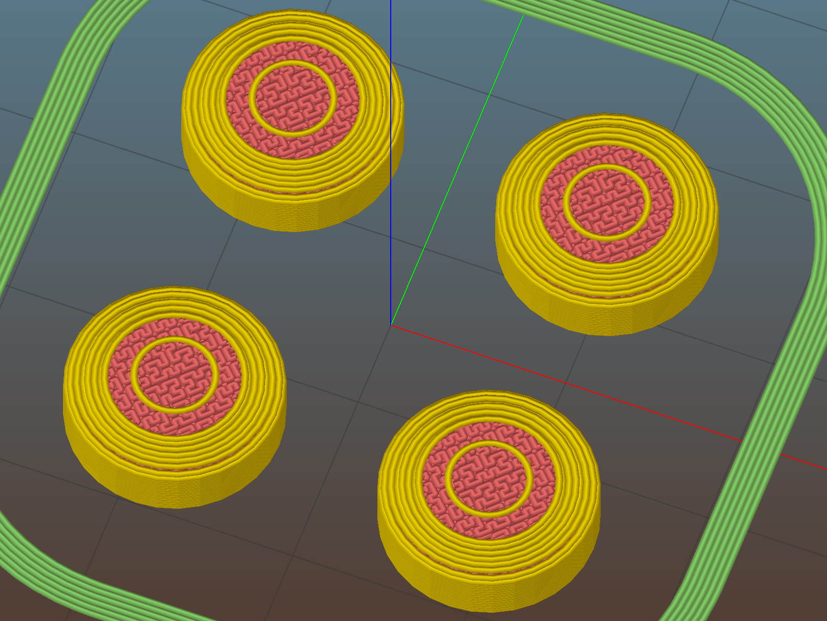
PTT Button Cap – Slic3r preview
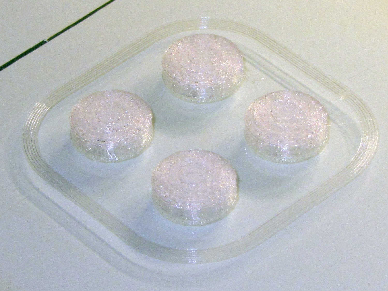
As with all small objects, building them four at a time gives the plastic in each one time to cool before slapping the next layer on top:
PTT Button – on platform
The hole in the cap is 0.2 mm oversize, which results in a snug press fit on the small ridges barely visible around the post in the first image:
PTT Button – rounded cap
Rather than compute the chord covering the surface, I just resized a sphere to twice the desired dome height (picked as 6 threads, just for convenience) and plunked it atop a cylinder. Remember to expand the sphere diameter by 1/cos(180/sides) to make it match the cylinder and force both to have the same number of sides.
This file contains hidden or bidirectional Unicode text that may be interpreted or compiled differently than what appears below. To review, open the file in an editor that reveals hidden Unicode characters.
Learn more about bidirectional Unicode characters
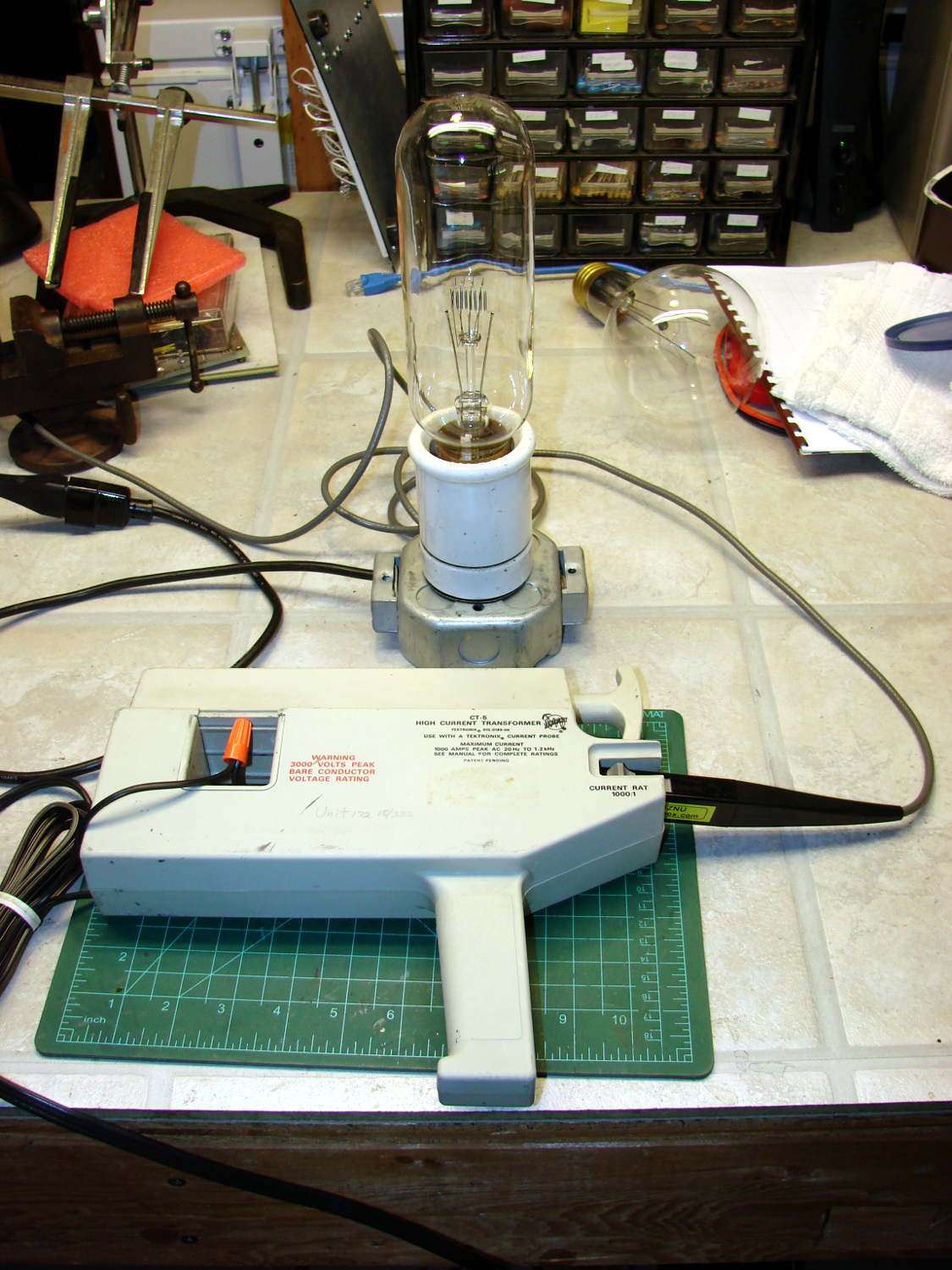
When a 100 A current probe won’t do the job, another order of magnitude can make all the difference:
Tek CT-5 A6302 Current Probe – 500 W bulb
That’s a Tektronix CT-5 current transformer, rated for 1 kA between -3 dB points at 0.5 Hz and 20 MHz, with an A6302 20 A probe snapped around its 1000:1 output winding.
The eBay deal didn’t include the 015-0190-00 1000:1 bucking coil that lets you measure small AC signals against high DC current; if you happen to find one for considerably less than the $100 I was unwilling to pay, let me know. I doubt I’ll ever need it, but ya never know.
Lacking a calibrated current source with sufficient moxie to exercise the thing, I settled for a 500 W incandescent bulb: 514 W and 4.38 A rms, according to a Kill-A-Watt meter off to the left.
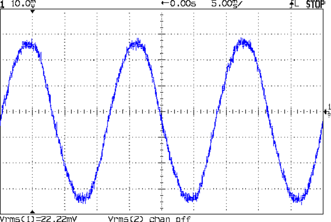
The 1000:1 output, seen through the A6302 probe at 2 mA/div = 2 A/div:
Tek CT-5 A6302 – 2 mA div 1000 ratio – 514 W 4.38 A
The 22.22 mVrms corresponds to 4.4 A = (22.22 / 10) * 0.002 * 1000.
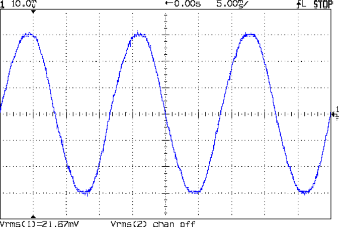
Moving the probe to the 20:1 output at 100 mA/div = 2 A/div:
Tek CT-5 A6302 – 100 mA div 20 ratio – 514 W 4.38 A
Again, the scope’s 21.67 mVrms works out to 4.3 A = (21.67 / 10) * 0.1 A * 20.
Over the past few months I picked up a pair of Tektronix AM503 Current Probe Amplifiers, plus A6302 20 A and A6303 100 A Hall effect probes. The proper calibration procedures require rather specialized (and, in some cases, custom-built) equipment that I don’t have, but I’ll mostly use these things for non-contact / isolated current measurements where just seeing what’s going on counts for more than absolute accuracy.
For a quick check, I set up a pair of 100 W incandescent bulbs with a plug/socket that breaks out the line conductor into a widowmaker zip cord intended for a foot switch, but I’m not fussy:
Tektronix A6302 A6303 Current Probes – test load
That’s an old (pronounced “vintage” in eBay-speak) Radio Shack (“Micronta”) clamp-on AC ammeter that, for my present purposes, I can regard as the Gold Standard for current measurement. The 200 W resistive load reads 1.6 A, which is pretty close to the 1.7 A you’d expect.
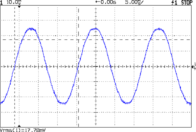
The big A6303 probe loafs along at the low end of its range:
Tek A6303 probe – 200 W incandescent
The scope says 17.78 mV RMS, which translates to 1.8 A with the AM503 set to 1 A/div. A bit hot, perhaps, but not off by too much.
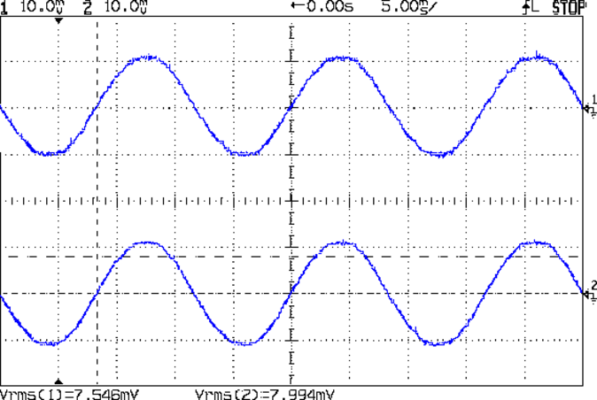
The two AM503 amps produce slightly different results when switching the probes back and forth, but this arrangement looks consistent:
Tek A6303 A6302 probes – 1.6 A rms
With the AM503 amps set to 2 A/div, 7.546 mV = 1.5 A and 7.994 mV = 1.6 A. The last few digits of those RMS calculations absolutely don’t matter.
The overall error (at least for low-range AC) looks to be around 10%, which is certainly good enough for my immediate needs. I doubt that I can gimmick up a square wave current calibration fixture that I’d trust.
Labeling the amps improves the odds that I’ll plug the probes in correctly:
Tektronix TM502 Mainframe with AM503 Current Probe Amps
The A6303 amp lights the “high range” indicator, the A6302 lights the “low range” indicator. Newer (but still obsolete) AM503A and AM503B amps have an LED readout showing the current/division, but …
With a new motor and controller in the reconfigured SqWr Power Wheels chassis, I made a few measurements under somewhat less than controlled conditions, with the butt end of the chassis on jack stands. The general idea was to find out what the “lightly loaded” condition looked like in terms of motor current; after some mechanical and electrical improvements, we’ll be in a better position to determine the battery load & suchlike.
Preliminary measurements:
Motor DC resistance: 0.7 Ω (meter lead resistance 0.2 Ω, so don’t trust it)
Motor winding inductance: 128 µH
Motor shaft key: 1/8 inch (keyway chewed by pulley setscrews, needs matching shaft flats)
Twist-grip throttle applies nonzero voltage when released: possibly damaged
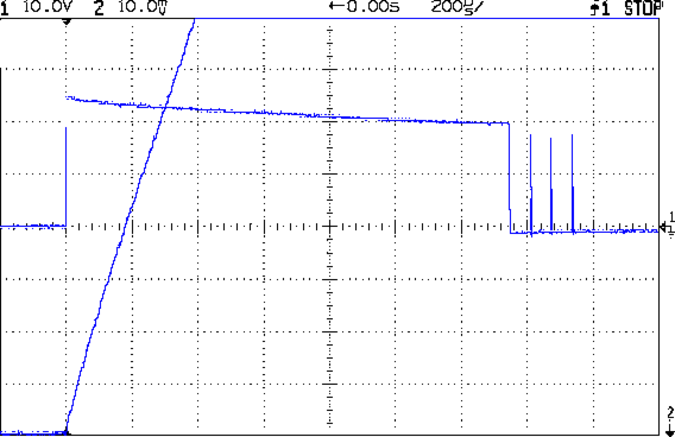
With everything in position and the Tek 6303 probe set for 10 A/div, this is what happens when you push the deadman switch:
Out V I 10 A – start transient
Obviously, the motor controller takes much too long to wake up & sense the current.
The initial slope of that current waveform looks like 80 A/360 µs = 220 kA/s. The upper trace gives the motor voltage, so 23 V / (220 kA/s) = 104 µH, surprisingly close to the measured 128 µH.
Deploying the mighty Tek CT-5 (with an enclosed A6302), cranking the gain to 50 A/div, and poking the deadman again:
Out V I 50 A – start transient full
During that initial pulse, the controller connects the battery directly to the motor, so you’re looking directly at 200 A of battery current. For reasons that aren’t relevant here, the mandatory 60 A safety fuse isn’t present, although it should be able to withstand a millisecond or two of moderate overload without blowing.
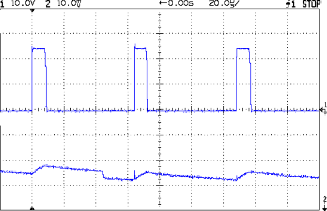
With that out of the way and the motor running at a few hundred RPM, due to the nonzero twist-grip output voltage with no throttle applied, the controller actually does PWM pretty much as you’d expect:
Out V I 10 A – run low speed
It’s not clear what caused the small dent just before the middle pulse; perhaps the motor commutator switched from one winding to the next.
The battery current will be much lower than the motor current in this mode, roughly (motor current) * (PWM fraction). We haven’t verified that, but for 30% PWM it should be around 5 A = 15 A * 0.30. The actual battery current looks smoother than I expected, although I have no traces to show for it; more study is needed.
Eks once again graciously loaned me his Tek current probes; this whole Power Wheels mess motivated me to get off my ass and accumulate my own collection, about which more later.
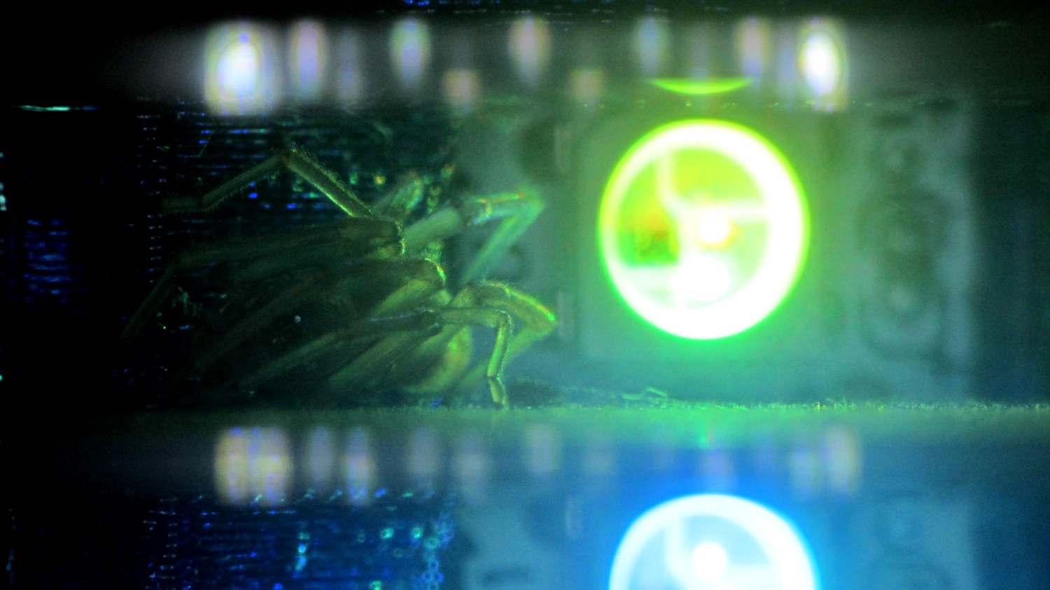
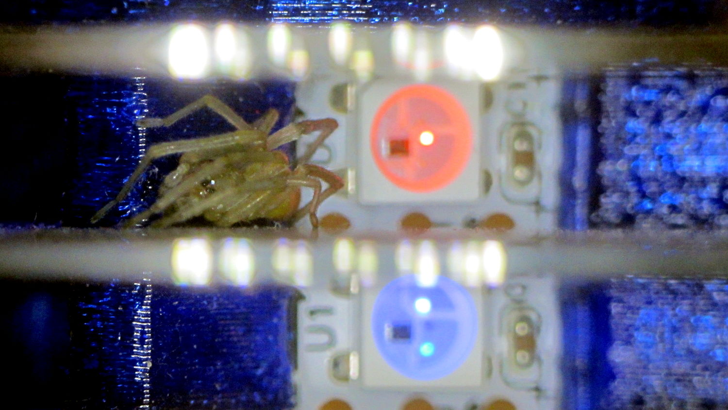
Another of the knockoff Neopixels in the Hard Drive Platter Mood Light failed, even limited to PWM 63 to reduce the temperature. This time, however, I had some help finding the failed blue LED:
Hard Drive Mood Light – failed LED with spider – green
Hard Drive Mood Light – failed LED with spider – white
A day later, she’d built a small web, presumably to improve the odds of catching something yummy. Who am I to disagree?
I should set up a test fixture for all the knockoff Neopixels and run some numbers. They’re definitely a disappointment, even to a bottom feeder such as I …