The single moving part on my first-generation (2011) Kindle Fire tablet stopped working: the power switch became erratic, to the point where the only dependable way to turn the thing on required the USB charging cable. Obviously not a long-term solution.
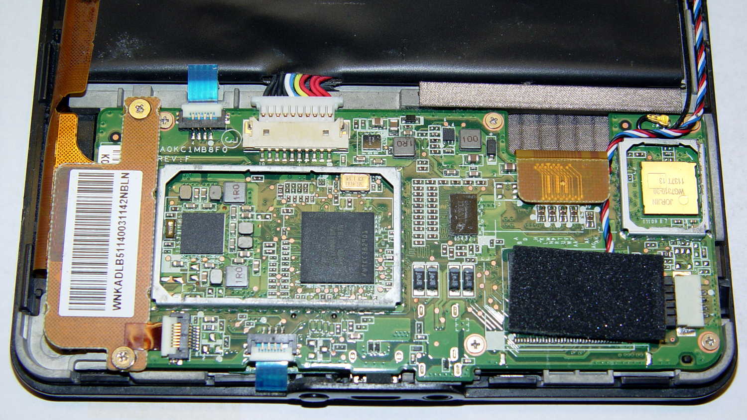
Having nothing to lose, I consulted the Internet’s vast steaming pile of advice on how to pop the Kindle’s cover, picked one, and ran with it. Basically, you jam a sharp tool into the end with the speakers, then crack the back off along both sides, leading to this:
Things to note:
- No need to remove the battery: pull the heavy connector straight out
- Disconnect the battery first, before unplugging anything else
- Most of the ribbon cable connectors have a white flip-up latch
- You will break the ground shield from the flex PCB to the battery along the left edge
- The antenna must make that 270° turn into the minuscule U.FL connector
- The four-wire cable to the speakers has a pull-out connector in the lower right corner
- The PCB backplate on the large video (?) connector in the upper right pulls straight up-and-out
Remove the six obvious screws, pull the battery edge of the board upward, and rotate the whole affair out of the chassis:

Protip: the power switch is not mounted on the tiny PCB (under the ribbon cable with the blue tab) sometimes advertised as the Power Button Board. That tiny PCB suspends an amber/green LED behind the visible button, but a yoke surrounds the LED to transfer the button motion to the power switch soldered to the CPU board. Replacing that board will not cure an erratic power switch; I think the entire CPU board is the FRU.
Fortunately, I can actually see the power switch and know sorta-kinda what to expect.
A bit of awkward multimeter probing showed the switch was defunct, with intermittent action and generally high resistance when pressed. I unsoldered the switch, verified that it didn’t work in isolation, and examined some likely candidates from the Big Box o’ Small Switches:

Some could be made to fit and maybe actually function, with effort ranging from tedious to Really Hard.
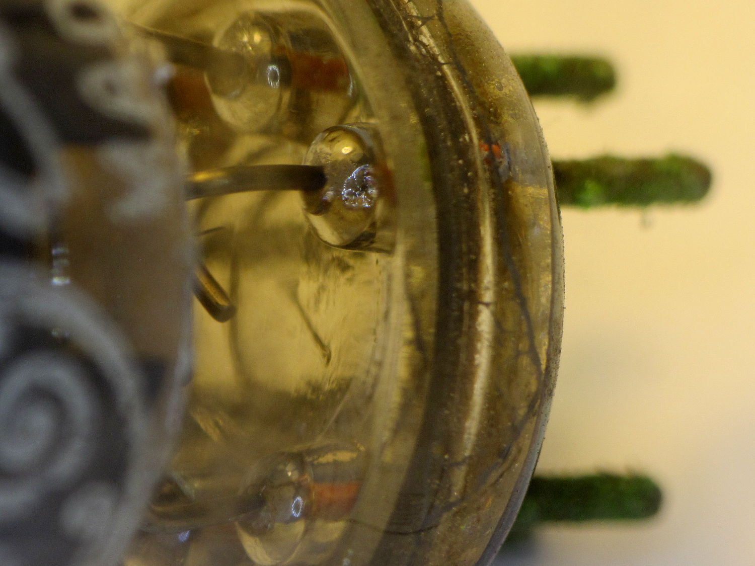
Then it occurred to me that maybe, just maybe, I could refurbish / clean / repair the Kindle’s switch contacts. Shaving off the two heat-staked plastic bumps on the front and prying the side latches outward produced an explosion of small parts:
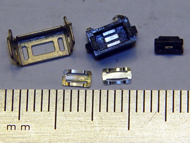
That’s after cleaning the expected grunge from the three contact strips in the body and the innermost of the two (!) buckling-spring contact doodads (bottom left). I scrubbed with the cardboard-ish stem of a cotton swab and, as always, a dot of DeoxIT Red, inserted the unused-and-pristine contact spring doodad (bottom right) first, and reassembled the switch in reverse order.
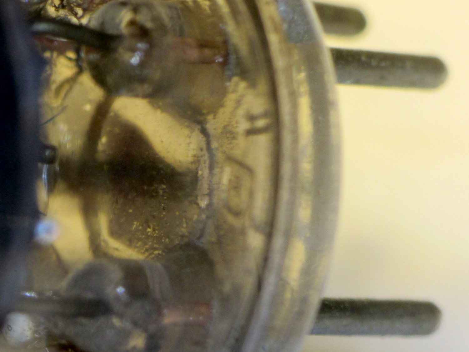
The metal shell around the body has two locating tabs that fit in two PCB holes, giving the switch positive alignment and good strain relief. The front view shows the three human-scale components amid a sea of 0201 SMD parts:

For completeness, the view from the battery side:

It’s worth noting that you can see right through the 3.5 mm headphone jack, which accounts for the remarkable amount of dust & fuzz I blew out of the chassis. The overall dust sealing isn’t great, but after five years of life in my pocket, I suppose that’s to be expected.
Installing the board requires holding all the cables out of the way (tape the antenna & speaker wires to the battery), aiming the USB connector into its cutout, rotating the battery edge of the board downward, pushing the mesh EMI shield along the battery upward to clear the board edge, not forcing anything, and eventually it slides into place.
Insert cables, latch latches, plug in the battery, snap the rear cover in place, and It Just Works again. The power switch responds to a light touch with complete reliability; it hasn’t worked this well in a year.
Bonus: To my utter & complete astonishment, disconnecting the battery for few hours had no effect on the stored data: it powered up just fine with all the usual settings in place. I expected most of the settings to live in the Flash file system, but apparently nothing permanent lives in RAM.
Take that, entropy!