Ed Nisley's Blog: Shop notes, electronics, firmware, machinery, 3D printing, laser cuttery, and curiosities. Contents: 100% human thinking, 0% AI slop.
Ham-It-Up Test Signal source – LTSpice Schmitt params
All of which come together and produce a waveform (clicky for more dots):
Ham-It-Up Test Signal source – LTSpice waveform
Which suggests the Test Signal ticks along at tens-of-MHz, rather than the tens-of-kHz I expected from the birdies in the filtered 60 kHz preamp response.
Of course, hell hath no fury like that of an unjustified assumption, so actually measuring the waveform would verify the cap value and similar details.
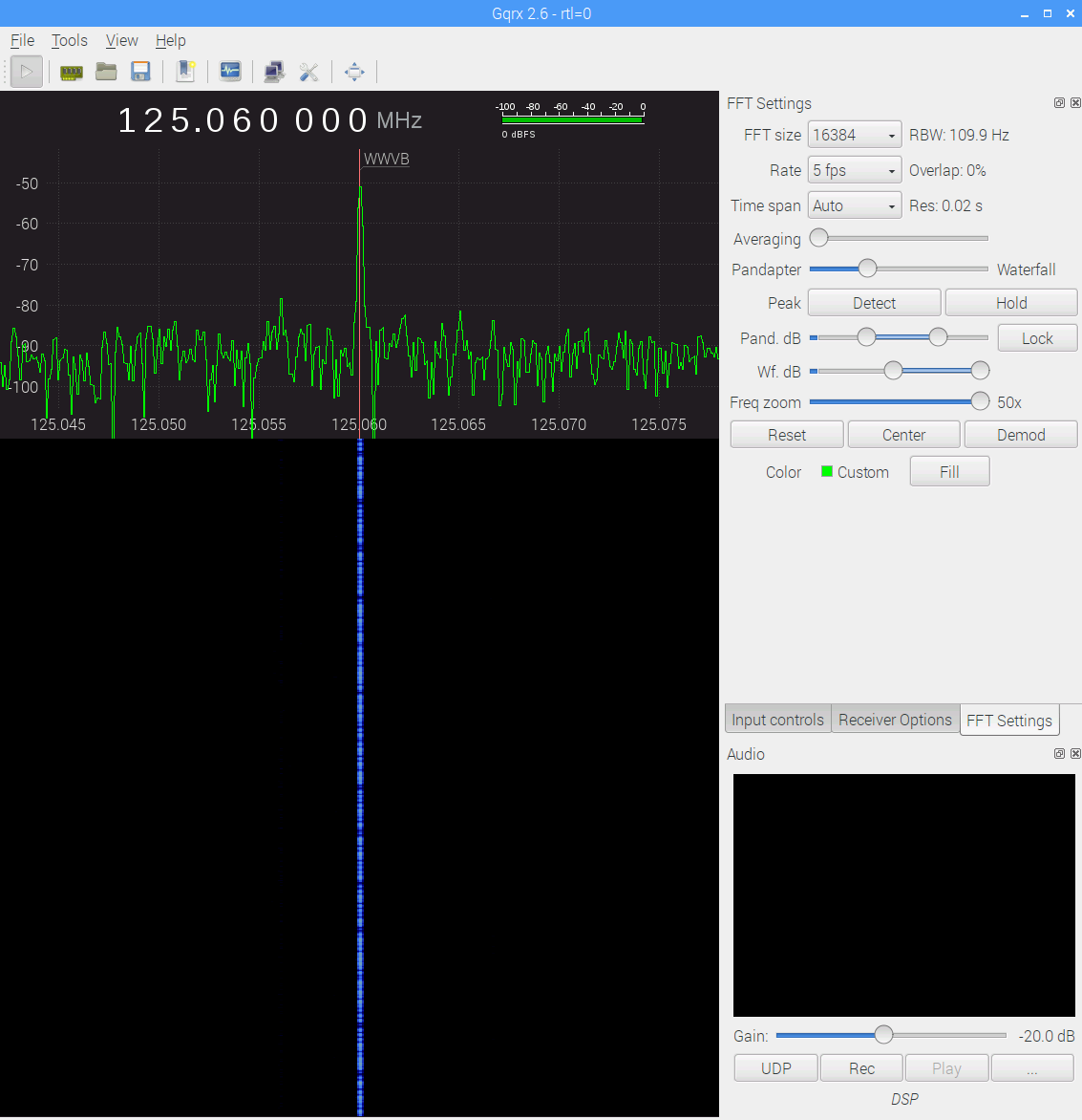
The big spike over on the left at 125.000 MHz comes from the Ham-It-Up local oscillator. A series of harmonics starting suspiciously close to 125.032768 kHz produces the oneat 125.066 MHz, just to the right of the WWVB signal, which leads me to suspect a rogue RTC in the attic.
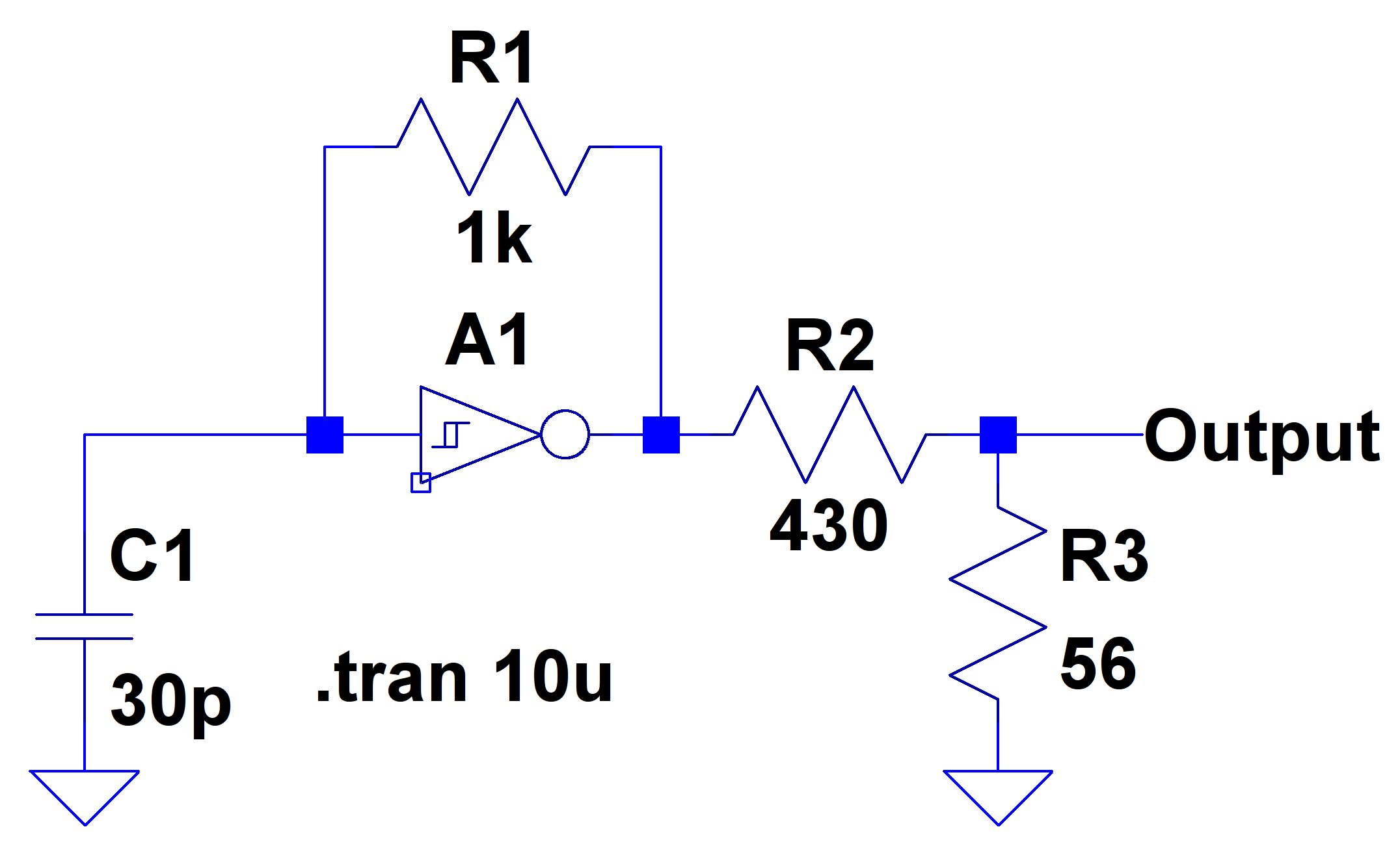
There is, in fact, a free running “Test Signal Source” on the Ham-It-Up board:
Ham-It-Up Test Signal source – schematic
Although I have nary a clue about that bad boy’s frequency, measuring it and cutting the inverter’s power trace / grounding the cap may be in order.
The SDR’s AGC contributes about 30 dB of gain, compresses the hottest signals at -25 dB, and raises those harmonics out of the grass, so it’s not an unalloyed benefit. Manually cranking on 10 dB seems better:
WWVB – xtal filter – waterfall – 10 dB hardware preamp – 2017-11-16 0630 EST
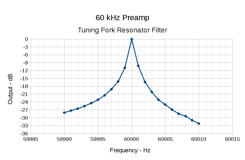
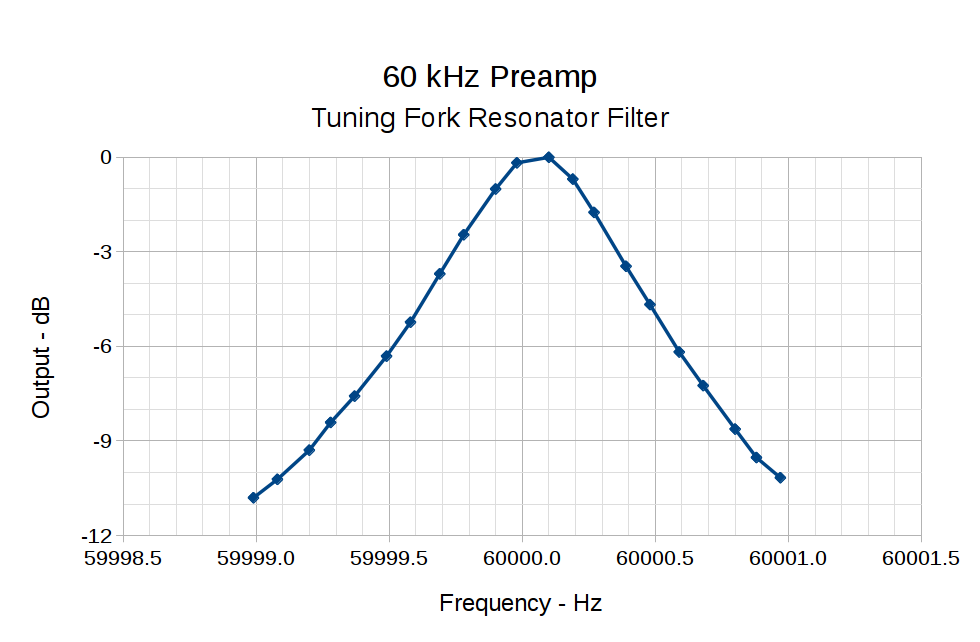
The bump in the middle shows the WWVB preamp’s 2 kHz bandwidth around the 60 kHz filter output, so the receiver isn’t horribly compressed. The carrier rises 30 dB over that lump, in reasonable agreement with the manual measurements over a much narrower bandwidth:
60 kHz Preamp – Bandwidth – 1 Hz steps
With all that in mind, a bit of careful tweaking produces a nice picture:
WWVB – xtal filter – waterfall – 10 dB hardware preamp – 2017-11-16 0713 EST
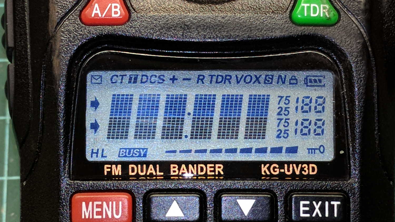
Radio communication between our bikes failed on the way back from a grocery ride and the problem turned out to be a failed radio:
Wouxun KG-UV3D – defunct
The Wouxun KG-UV3D radio seems jammed firmly somewhere in its power-up sequence, doesn’t respond to any buttons, and has no hard-reset switch. On the other paw, it’s been in constant (and rugged!) use for almost exactly five years, so I suppose it doesn’t owe me much of anything.
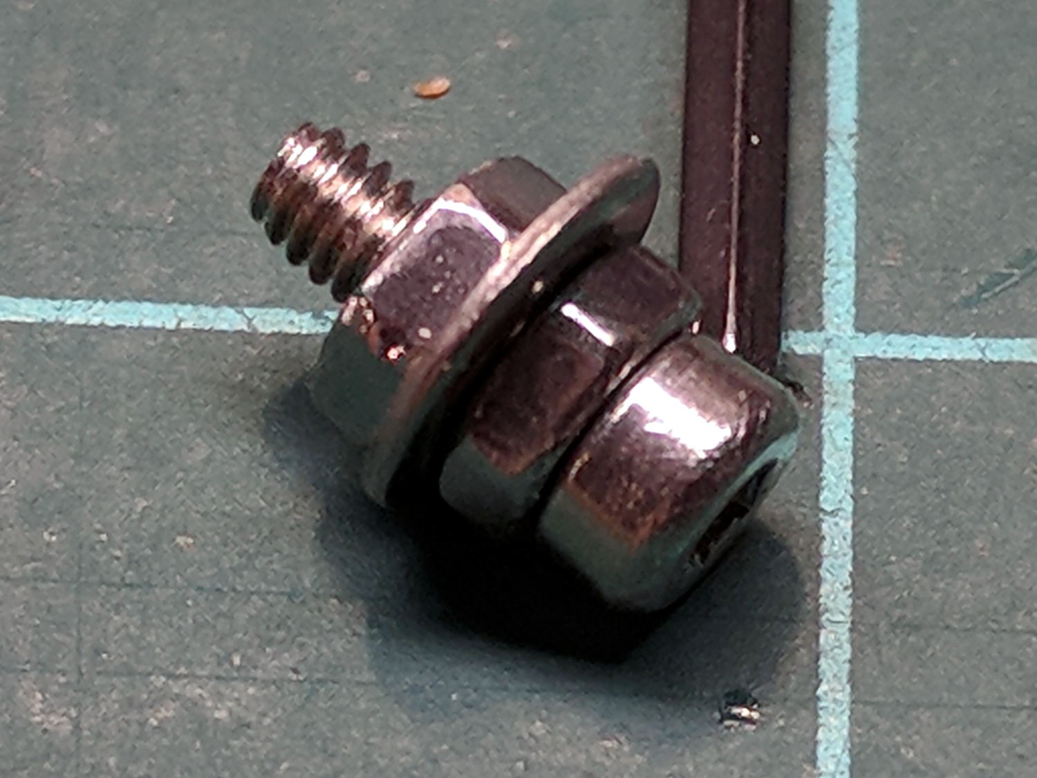
The new radio, another KG-UV3D from PowerWerx, has marginally different spacing around the screw attaching the plug cover preventing the previous screw from fitting, so I kludged up a screw from a 2 mm socket-head screw, a 2.5 mm (yes) washer, and a pair of 2 mm nuts:
Wouxun KG-UV3D – APRS plug plate screw
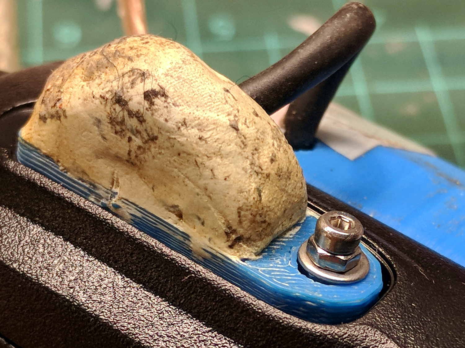
Which looks a bit odd, but holds the plug adapter plate firmly in place:
Wouxun KG-UV3D – APRS Voice Plug Block
I suppose when the radio on my bike fails, I must rebuild both APRS + voice interfaces for Yet Another Radio, because the Wouxuns will be completely unobtainable.
The weather abruptly became too cold for riding, at least for sissies such as we, but maybe we’ll get out later in the month …
A reader (you know who you are!) proposed an interesting project that will involve measuring audio passbands and suggested using white noise to show the entire shape on a spectrum analyzer. He pointed me at the NOISE 1B Noise Generator based on a PIC microcontroller, which led to trying out the same idea on an Arduino.
The first pass used the low bit from the Arduino runtime’s built-in random() function:
Arduino random function bit timing
Well, that’s a tad pokey for audio: 54 μs/bit = 18.5 kHz. Turns out they use an algorithm based on multiplication and division to produce nice-looking numbers, but doing that to 32 bit quantities takes quite a while on an 8 bit microcontroller teleported from the mid 1990s.
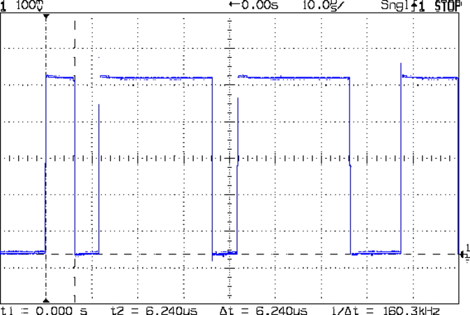
The general idea is to send a bit from the end of a linear feedback shift register to an output to produce arandomly switching binary signal. Because successive values involve only shifts and XORs, it should trundle along at a pretty good clip and, indeed, it does:
Arduino Galois shift reg bit timing
I used the Galois optimization, rather than a traditional LFSR, because I only need one random bit and don’t care about the actual sequence of values. In round numbers, it spits out bits an order of magnitude faster at 6 μs/bit = 160 kHz.
The spectrum looks pretty good, particularly if you’re only interested in the audio range way over on the left side:
Arduino Galois bit spectrum
It’s down 3 dB at 76 kHz, about half the 160 kHz bit flipping pace.
If you were fussy, you’d turn off the 1 ms timer interrupt to remove a slight jitter in the output.
It’s built with an old Arduino Pro Mini wired up to a counterfeit FTDI USB converter. Maybe this is the best thing I can do with it: put it in a box with a few audio filters for various noise colors and be done with it.
It occurs to me I could fire it into the 60 kHz preamp’s snout to measure the response over a fairly broad range while I’m waiting for better RF reception across the continent.
This file contains hidden or bidirectional Unicode text that may be interpreted or compiled differently than what appears below. To review, open the file in an editor that reveals hidden Unicode characters.
Learn more about bidirectional Unicode characters
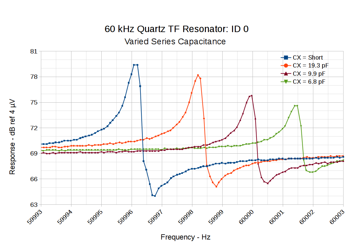
Putting a small capacitor in series with the tuning fork resonator pulls the series resonant frequency upward and reduces the amplitude:
60 kHz Quartz TF Resonator – CX variations
So something around 10 pF, net of stray capacitance and suchlike, should suffice. Plunk a small twiddlecap on the preamp board and tune for best picture:
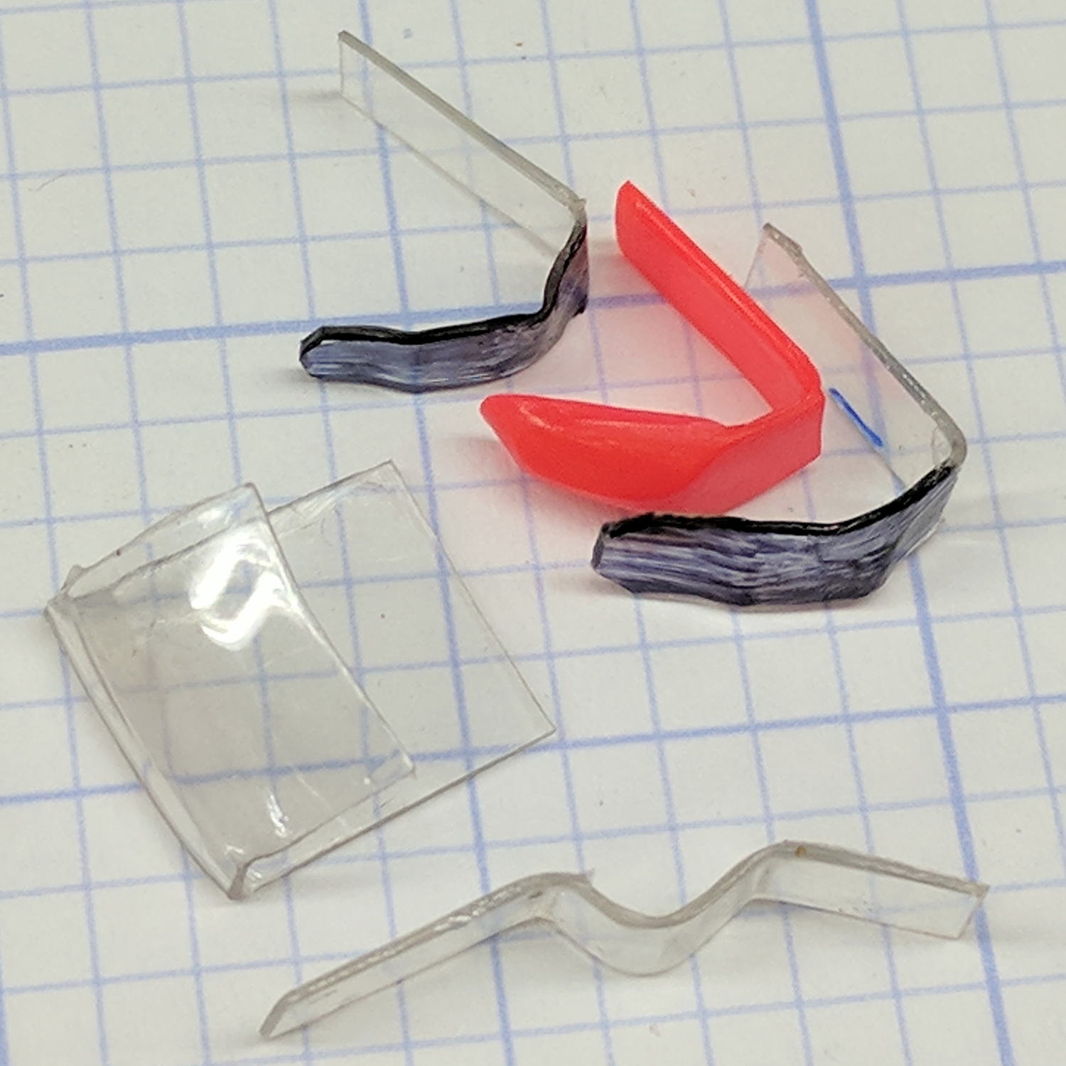
Over the course of a few weeks, both of the indicators in the SRAM grip shifters on my bike snapped off. Having recently touched my parallel jaw clamp assortment, it occurred to me I could mold snippets of polypropylene sheet (saved from random clamshell packages for just such a purpose) around the nose of a clamp and come out pretty close to the final shape:
SRAM Shift Indicator – shaped replacements
A hot air gun set on LOW and held a foot away softened the polypro enough so a gloved thumb could squash it against the jaw. Too much heat shrinks the sheet into a blob, too little heat lets the sheet spring back to its original shape.
The flat tab of the original indicator is about 1 mm thick. I found a package of 47 mil = 1.2 mm sheet with one nice right-angle bend and ran with it.
Because I expect sunlight will fade any color other than black, that’s the Sharpie I applied.
They don’t look as awful as you might expect. The rear shifter, minus the cover:
SRAM Shift Indicator – rear detail
The front shifter, with cover installed and HT PTT button below the still-good Kapton tape:
SRAM Shift Indicator – front assembled
The transparent covers press the OEM indicators down and do the same for my homebrew tabs. I expect the Sharpie will wear quickly at those contact points; next time, I should tint the other side.
They’re rather subtle, I’ll grant you that.
Now, to see if they survive long enough to make the worry about a brighter color fading away a real problem…
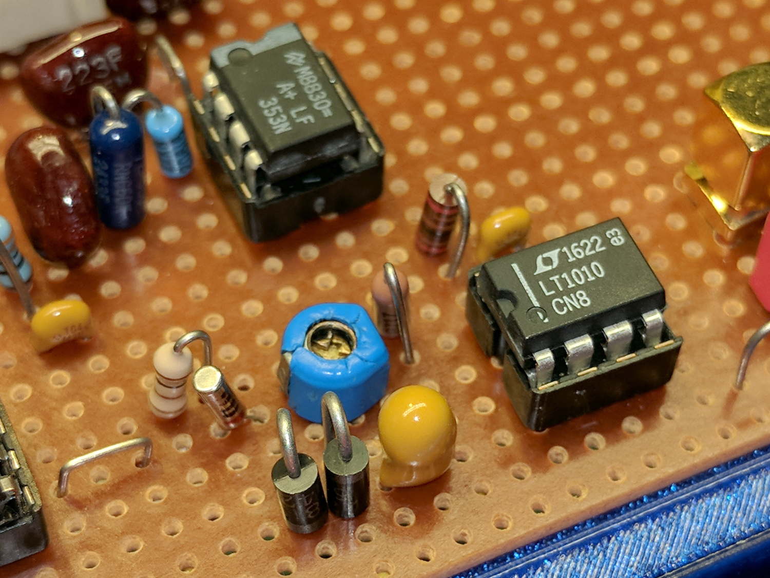
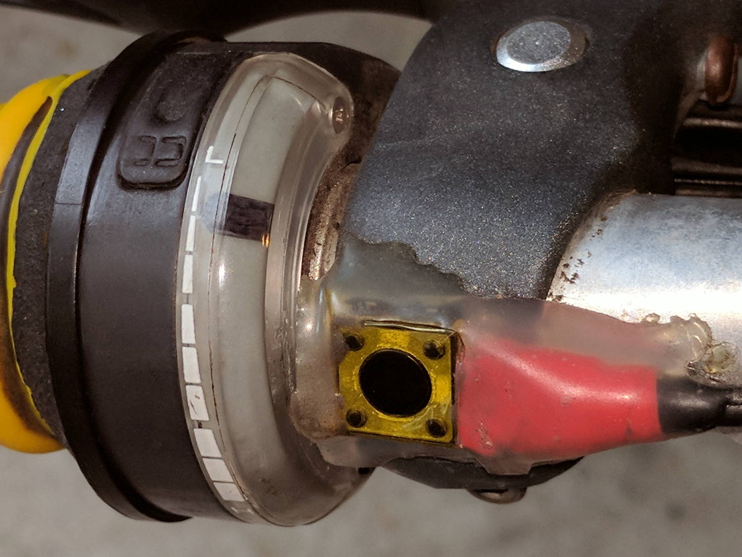
The LT1920 instrumentation amplifier now sports two silver-mica caps on its inputs as a differential-mode input filter cutting back strong RF signals (clicky for more dots):
In principle, a DM filter should eliminate RF rectification from out-of-band signals, although I think the attic is quiet enough to not need any help. The caps form a simple RC LP filter rolling off at 5.490 kΩ × 150 pF → 193 kHz, high enough above the 60 kHz signal to not make much difference down there.
The silver-mica caps come from the Big Box o’ Caps, which contained an envelope with a few large 150 pF ±1% caps and a bag stuffed with similar 147 pF ±1% caps. Mixed in with the latter were some smaller 147 pF caps (*) of no particular tolerance (perhaps 5%), from which I neurotically matched a pair to 0.05 pF without too much effort. Doesn’t matter, given the other tolerances and suchlike, but it was amusing.
I’d inadvertently grounded the cold end of the 330 Ω input resistor in the LM353 bandpass filter, now properly tied at the Vcc/2 virtual ground to take the DC load off the LT1920 output: a 100 nF cap (27 Ω at 60 kHz) stores the bias level without messing up the filter shape.