The pair of air-wired inductors and resistors simulate the 60 kHz resonant loop antenna:
I didn’t include a pair of capacitors to simulate the antenna’s stray capacitance, as the resonance is so broad and my signal so strong that pretty nearly anything will work.
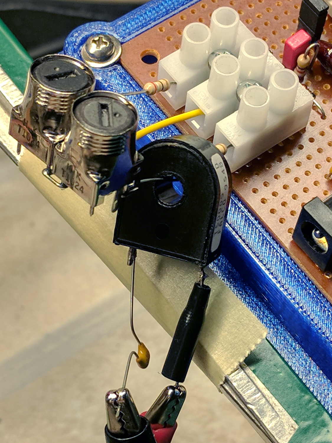
The current transformer injecting a differential signal into the “antenna” came without provenance; it measures 3 Ω DC resistance and 140 mH inductance, so it most likely has a bazillion turns. A 50 pF cap would resonate it at 60 kHz, where both reactances would be 53 kΩ, which also doesn’t matter.
The alligator clips come from the LF Crystal Tester‘s buffer amp, with the Arduino Nano loaded with sine generator firmware. A 100 nF cap blocks the buffer’s DC bias, a 3.3 kΩ resistor (inside the heatstink tubing) knocks the signal down a bit, and it works pretty well:

The upper trace is the DDS buffer output at the clip leads and the lower trace is the preamp output.
The output of the LT1920 instrumentation amplifier (not shown) is 4.7 mVrms with a 20 dB gain, so the differential input runs a bit under 500 μV at the antenna terminals. That’s hotter than you’d expect from real WWVB RF, at least in the off season.
Looking in the other direction, the net gain through LF353 bandpass filter and resonator works out to 22 dB, so the resonator isn’t all that lossy right in the middle of its passband. Yes, I’m cheating: I tweaked the series cap for maximum output at 60.000 kHz input.
Good enough for a first pass, though, and makes for easy measurement.

Comments
One response to “60 kHz Preamp: Antenna Input Tickler”
[…] occurs to me I could fire it into the 60 kHz preamp’s snout to measure the response over a fairly broad range while I’m waiting for better RF reception […]