Ed Nisley's Blog: Shop notes, electronics, firmware, machinery, 3D printing, laser cuttery, and curiosities. Contents: 100% human thinking, 0% AI slop.
It’d be nice to get Slashdotted or Hackaday-ed for something techie, rather than bedbugs again …
Surprisingly, most visitors arrive from image searches, rather than text searches:
2012 YTD Blog Referrer Stats
The largest non-search-engine referrer was Google Reader at 4000, followed by a Lifehacker traffic spike at 3000, and then everything else. As far as search engines go: Google and debris.
In round numbers, 650 visitors get 1000 total views per day; the overall views/visitor runs around 1.75, which I interpret to mean most folks find exactly what they want on the first page. As nearly as I can tell from the daily stats, 300 of you visit the main page and post-of-the-day, plus another 100 click in from the RSS feed. The numbers don’t add up, primarily because RSS feed clicks don’t seem to enter into their totals.
It’s definitely not a get-rich-quick scheme, that’s for sure…
It’s still fun and I really do use this blog as my notebook: some of those searches come from me. I appreciate you folks helping me out with useful comments and suggestion: thanks!
The collection of refrigerator words went off to college for the amusement and edification of our Larval Engineer’s compadres. These magnetic words emerged from nooks and crannies on and around the refrigerator over the next few months and form what must be the Ultimate Message from the Subconscious:
For reasons best left to the imagination, we needed some large signs for the front yard. I must look this up every time I do it, so here’s the process…
Create document in LibreOffice (or whatever), save as PDF
Convert PDF to EPS = Encapsulated Postscript
Apply poster to enlarge & paginate
Convert PS to PDF for ease of printing
Bash does the heavy lifting, after you install whatever packages your Linux distro may not have included:
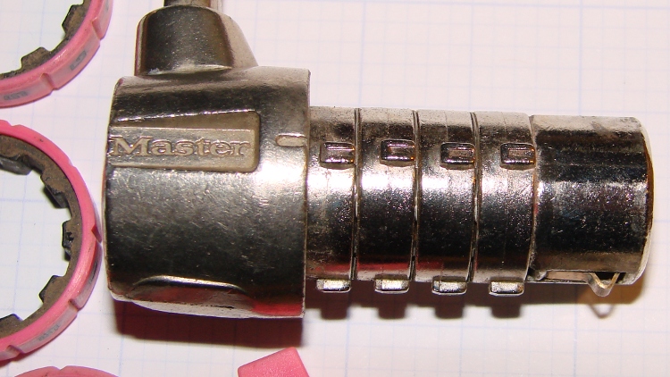
A Master Combination Lock emerged in locked condition from a box o’ stuff I handled during Mad Phil’s Great Cleanout. It’s not the highest security lock you’ll ever meet; about 15 minutes of fiddling produces the desired result:
Master Combo Padlock – opened
A bit of searching suggests it’s similar to the Master No. 1523D Combination Padlock, although this one came in pink. The doc describes how to change the combination:
Unlock (or crack) the lock
Pull off the spring-loaded endcap (I had to pry with a screwdriver)
Slide off the combination wheels
Reinstall in desired orientation
After removing the cap and wheels, it looks like this:
Master Combo Padlock – wheels off
Each wheel fits onto a rotating metal disk and engages three teeth, one of which has a notch. Align all four notches with the Master logo / index line and the lock opens:
Master Combo Padlock – dial alignment marks
Given just that picture, I think you can figure out how to get past one of these in a hurry. Right?
Based on that circuit simulation, the LED Stress Tester schematic looks about like you’d expect:
LED Stress Tester Schematic – updated
[Update: Left out the Schottky diode that makes the 20% duty cycle actually work. Drat & similar remarks.]
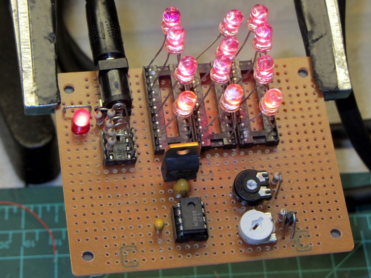
The manual wiring turned into a hairball, but from the top it looks pretty good:
LED Stress Tester – red and amber LEDs
The 20 pin DIP IC sockets provide spare contacts, so that ruining a few by jamming fat LED leads into them won’t be a tragedy. Each LED string uses one of three adjacent contacts, which left room for a fourth string of amber LEDs that are, even to the naked eyeball, nearly indistinguishable from the red LEDs.
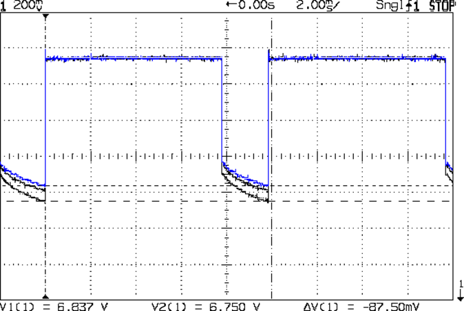
The 555 timer output waveform looks just like the simulation:
Timer Waveform
The trimpots sit near the middle of their rotations, which is always comforting. The duty cycle trimpot can’t quite get down to 1 ms, which doesn’t matter right now.
This scope shot shows the total forward drop across the three LED strings, with V=0 offset way down below the bottom of the display:
Red LED – group Vf
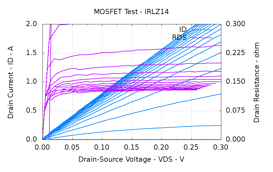
That voltage includes the IRLZ14 MOSFET drain-source voltage, which amounts to a bit less than the thickness of the fuzz on the traces. In round numbers:
VDS = 400 mA x 0.100 mΩ = 40 mV
That’s based on this measurement from the MOSFET tester a while back:
IRLZ14 detail
You could argue the drain voltage is closer to 60 mV. I’d argue that the overall accuracy of all these measurements leaves a lot to be desired; we’re in the right ballpark no matter what.
Anyhow.
From the top, the three traces show LED groups 7-9, 1-3, and 4-6 in exactly the predicted order (1-3: 6.445, 4-6: 6.372, and 7-9:6.469 V), if not with exactly the predicted absolute voltages.
Part of the reason may be that the current limiting resistors that produced about 100 mA were 5.6 Ω, rather than the predicted 10 Ω, They actually measure about 5.7 Ω and the forward drop (from that scope shot) is around 750 mV, so the current could be up around 130 mA: a bit hot. I want to measure the current more closely before leaping to any conclusions.
The 1/4 W ballast resistors dissipate 100 mW peak / 20 mW average and each LED dissipates 300 mW peak and 60 mW average.
The 7.5 V wall wart I planned to use requires a much higher average load for good regulation (it emits 10.5 V for light loads), so this lashup runs from that 2 A bench supply through the other end of the Tek banana cable I hacked apart to make those SMD tweezers. The supply voltage at the coaxial jack drops by about 120 mV during the pulse, but we’re dealing with measurements up from ground.
I think the exponential curve in that scope shot shows the LED internal temperature rise during the pulse. If you figure -2 mV/°C (based on the ever-reliable and always accurate Wikipedia), then the 150 mV change along the exponential works out to 50 mV per LED and a 25 °C temperature rise. I have no idea whether thermal-cycling the LEDs at 100 Hz will cause early bond wire failure or not, which is why I want to let this run for a month or so.
While wiring up the LED stress tester, I realized I should abuse a string of amber LEDs along with the three red strings. Herewith, four amber LEDs from the top of their bag, with LED 5 = LED 1 retested:
Amber LEDs – 100 mA
Apart from being an outlier, that red trace seems much prettier than the others, doesn’t it?
The Bash / Gnuplot routine that produced the graph has a few tweaks:
#!/bin/sh
numLEDs=4
#-- overhead
export GDFONTPATH="/usr/share/fonts/truetype/"
base="${1%.*}"
echo Base name: ${base}
ofile=${base}.png
echo Input file: $1
echo Output file: ${ofile}
#-- do it
gnuplot << EOF
#set term x11
set term png font "arialbd.ttf" 18 size 950,600
set output "${ofile}"
set title "${base}"
set key noautotitles
unset mouse
set bmargin 4
set grid xtics ytics
set xlabel "Forward Voltage - V"
set format x "%6.3f"
set xrange [1.8:2.2]
#set xtics 0,5
set mxtics 2
#set logscale y
#set ytics nomirror autofreq
set ylabel "Current - mA"
set format y "%4.0f"
set yrange [0:120]
set mytics 2
#set y2label "right side variable"
#set y2tics nomirror autofreq 2
#set format y2 "%3.0f"
#set y2range [0:200]
#set y2tics 32
#set rmargin 9
set datafile separator "\t"
set label 1 "LED 1 = LED $((numLEDs + 1))" at 2.100,110 right font "arialbd,18"
set arrow from 2.100,110 to 2.105,103 lt 1 lw 2 lc 0
plot	\
    "$1" index 0:$((numLEDs - 1)) using (\$5/1000):(\$2/1000):(column(-2)) with linespoints lw 2 lc variable,\
    "$1" index $numLEDs using (\$5/1000):(\$2/1000) with linespoints lw 2 lc 0
EOF
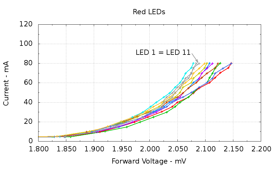
Running ten random red LEDs (taken from the bag of 100 sent halfway around the planet) through the LED Curver Tracer produces this plot:
Red LEDs – 80 mA
The two gray traces both come from LED 1 to verify that the process produces the same answer for the same LED. It does, pretty much.
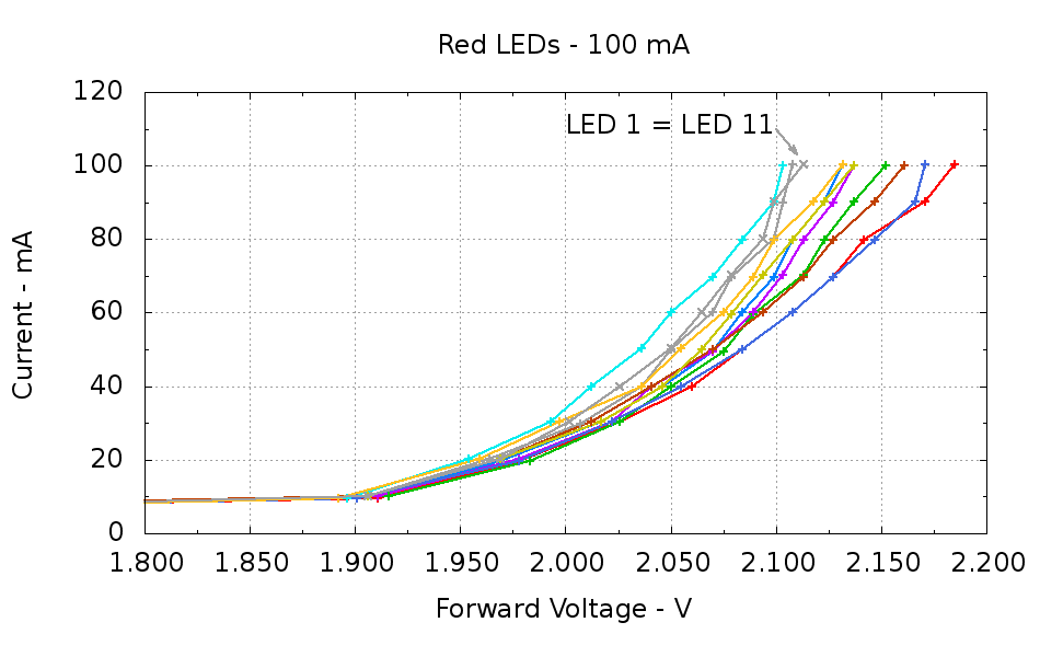
Repeating that with the same LEDs in the same order, but stepping 10 mA up to 100 mA produces a similar plot:
Red LEDs – 100 mA
The voltage quantization comes from the Arduino’s 5 mV ADC resolution (the readings are averaged, but there’s actually not much noise) and the current quantization comes from the step value in the measurement loop (5 mA in the first plot, 10 mA in the second). Seeing the LEDs line up mostly the same way at 80 mA in both graphs is comforting, as it suggests the measurement results aren’t completely random numbers.
Putting three red LEDs in series could produce a total forward drop anywhere between 6.309 V (3*2.103) and 6.555 V (3*2.185), a difference of nigh onto a quarter volt, if you assume this group spans the entire range of voltages and the whole collection has many duplicate values and you’re remarkably unlucky while picking LEDs. For this particular set, however, summing three successive groups of three produces 6.445, 6.372, and 6.469 V, for a spread of just under 100 mV. That suggests it’s probably not worthwhile to select LEDs for forward voltage within each series group of three, although matching parallel LEDs makes a lot of sense. I have no confidence the values will remain stable over power-on hours / thermal cycling / current stress.
The capacity plot for the Wouxun KG-UV3D lithium battery packs shows that there’s not a lot of capacity left after 7.0 V, so shutting down or scaling back to lower current wouldn’t be a major loss. However, it’s not clear a fixed resistor will do a sufficient job of current limiting with 6.5 V forward voltage across the LED string:
At 7.5 V, 100 mA calls for 10 Ω (drop 1 V at 100 mA)
At 8.2 V, 10 Ω produces 170 mA (1.7 V across 10 Ω)
At 7.0 V, 10 Ω produces 50 mA (0.5 V across 10 Ω)
Obviously, 170 mA is way too much, even by my lax standards.
A 100 mV variation in forward voltage between stacks, each with a 10 Ω resistor, translates into about 10 mA difference in current. This may actually call for current sensors and direct current control, although using a sensor per string, seems excessive. Low dropout regulators in current-source mode might suffice, but that still seems messy.
The test rig will run from a hard 7.5 V supply, which means I can use fixed resistors and be done with it.
The raw data behind those graphs, with LED 1 and LED 11 being the same LED:
#!/bin/sh
#-- overhead
export GDFONTPATH="/usr/share/fonts/truetype/"
base="${1%.*}"
echo Base name: ${base}
ofile=${base}.png
echo Input file: $1
echo Output file: ${ofile}
#-- do it
gnuplot << EOF
#set term x11
set term png font "arialbd.ttf" 18 size 950,600
set output "${ofile}"
set title "${base}"
set key noautotitles
unset mouse
set bmargin 4
set grid xtics ytics
set xlabel "Forward Voltage - V"
set format x "%6.3f"
set xrange [1.8:2.2]
#set xtics 0,5
set mxtics 2
#set logscale y
#set ytics nomirror autofreq
set ylabel "Current - mA"
set format y "%4.0f"
set yrange [0:120]
set mytics 2
#set y2label "right side variable"
#set y2tics nomirror autofreq 2
#set format y2 "%3.0f"
#set y2range [0:200]
#set y2tics 32
#set rmargin 9
set datafile separator "\t"
set label 1 "LED 1 = LED 11" at 2.100,110 right font "arialbd,18"
set arrow from 2.100,110 to 2.110,103 lt 1 lw 2 lc 0
plot    \
"$1" index 0:9 using (\$5/1000):(\$2/1000):(column(-2)) with linespoints lw 2 lc variable,\
"$1" index 10 using (\$5/1000):(\$2/1000) with linespoints lw 2 lc 0
EOF
And the Arduino source code, which bears a remarkable resemblance to the original firmware:
// LED Curve Tracer
// Ed Nisley - KE4ANU - December 2012

#include <stdio.h>

//----------
// Pin assignments

const byte PIN_READ_LEDSUPPLY = 0;    // AI - LED supply voltage        blue
const byte PIN_READ_VDRAIN = 1;        // AI - drain voltage            red
const byte PIN_READ_VSOURCE = 2;    // AI - source voltage            orange
const byte PIN_READ_VGATE = 3;        // AI - VGS after filtering        violet

const byte PIN_SET_VGATE = 11;        // PWM - gate voltage            brown

const byte PIN_BUTTON1 = 8;            // DI - button to start tests    green
const byte PIN_BUTTON2 = 7;            // DI - button for options        yellow

const byte PIN_HEARTBEAT = 13;        // DO - Arduino LED
const byte PIN_SYNC = 2;            // DO - scope sync output

//----------
// Constants

const int MaxCurrent = 100;                // maximum LED current - mA
const int ISTEP = 10;                    // LED current increment

const float Vcc = 4.930;                // Arduino supply -- must be measured!

const float RSense = 10.500;            // current sense resistor

const float ITolerance = 0.0005;        // current setpoint tolerance

const float VGStep = 0.019;                // increment/decrement VGate = 5 V / 256

const byte PWM_Settle = 5;                // PWM settling time ms

#define TCCRxB 0x01                        // Timer prescaler = 1:1 for 32 kHz PWM

#define MK_UL(fl,sc) ((unsigned long)((fl)*(sc)))
#define MK_U(fl,sc) ((unsigned int)((fl)*(sc)))

//----------
// Globals

float AVRef1V1;                    // 1.1 V bandgap reference - calculated from Vcc

float VccLED;                    // LED high-side supply

float VDrain;                    // MOSFET terminal voltages
float VSource;
float VGate;

unsigned int TestNum = 1;

long unsigned long MillisNow;

//-- Read AI channel
//      averages several readings to improve noise performance
//        returns value in mV assuming VCC ref voltage

#define NUM_T_SAMPLES    10

float ReadAI(byte PinNum) {

word RawAverage;

digitalWrite(PIN_SYNC,HIGH);                // scope sync

RawAverage = analogRead(PinNum);            // prime the averaging pump

for (int i=2; i <= NUM_T_SAMPLES; i++) {
RawAverage += (word)analogRead(PinNum);
}

digitalWrite(PIN_SYNC,LOW);

RawAverage /= NUM_T_SAMPLES;

return Vcc * (float)RawAverage / 1024.0;

}

//-- Set PWM output

void SetPWMVoltage(byte PinNum,float PWMVolt) {

byte PWM;

PWM = (byte)(PWMVolt / Vcc * 255.0);

analogWrite(PinNum,PWM);
delay(PWM_Settle);

}

//-- Set VGS to produce desired LED current
//        bails out if VDS drops below a sensible value

void SetLEDCurrent(float ITarget) {

float ISense;                // measured current
float VGateSet;            // output voltage setpoint
float IError;                // (actual - desired) current

VGate = ReadAI(PIN_READ_VGATE);                    // get gate voltage
VGateSet = VGate;                                    //  because input may not match output

do {

VSource = ReadAI(PIN_READ_VSOURCE);
ISense = VSource / RSense;                        // get LED current

//    printf("\r\nITarget: %lu mA",MK_UL(ITarget,1000.0));
IError = ISense - ITarget;

//    printf("\r\nISense: %d mA VGateSet: %d mV VGate %d IError %d mA",
//           MK_U(ISense,1000.0),
//           MK_U(VGateSet,1000.0),
//           MK_U(VGate,1000.0),
//           MK_U(IError,1000.0));

if (IError < -ITolerance) {
VGateSet += VGStep;
//      Serial.print('+');
}
else if (IError > ITolerance) {
VGateSet -= VGStep;
//      Serial.print('-');
}

VGateSet = constrain(VGateSet,0.0,Vcc);
SetPWMVoltage(PIN_SET_VGATE,VGateSet);

VDrain = ReadAI(PIN_READ_VDRAIN);        // sample these for the main loop
VGate = ReadAI(PIN_READ_VGATE);
VccLED = ReadAI(PIN_READ_LEDSUPPLY);

if ((VDrain - VSource) < 0.020) {            // bail if VDS gets too low
printf("# VDS=%d too low, bailing\r\n",MK_U(VDrain - VSource,1000.0));
break;
}

} while (abs(IError) > ITolerance);

//    Serial.println(" Done");
}

//-- compute actual 1.1 V bandgap reference based on known VCC = AVcc (more or less)
//        adapted from http://code.google.com/p/tinkerit/wiki/SecretVoltmeter

float ReadBandGap(void) {

word ADCBits;
float VBandGap;

ADMUX = _BV(REFS0) | _BV(MUX3) | _BV(MUX2) | _BV(MUX1);    // select 1.1 V input
delay(2); // Wait for Vref to settle

ADCSRA |= _BV(ADSC);                                        // Convert
while (bit_is_set(ADCSRA,ADSC));

ADCBits = ADCL;
ADCBits |= ADCH<<8;

VBandGap = Vcc * (float)ADCBits / 1024.0;
return VBandGap;
}

//-- Print message, wait for a given button press

void WaitButton(int Button,char *pMsg) {
printf("# %s",pMsg);
while(HIGH == digitalRead(Button)) {
delay(100);
digitalWrite(PIN_HEARTBEAT,!digitalRead(PIN_HEARTBEAT));
}

delay(50);                // wait for bounce to settle
digitalWrite(PIN_HEARTBEAT,LOW);
}

//-- Helper routine for printf()

int s_putc(char c, FILE *t) {
Serial.write(c);
}

//------------------
// Set things up

void setup() {
pinMode(PIN_HEARTBEAT,OUTPUT);
digitalWrite(PIN_HEARTBEAT,LOW);    // show we arrived

pinMode(PIN_SYNC,OUTPUT);
digitalWrite(PIN_SYNC,LOW);        // show we arrived

TCCR1B = TCCRxB;                    // set frequency for PWM 9 & 10
TCCR2B = TCCRxB;                    // set frequency for PWM 3 & 11

pinMode(PIN_SET_VGATE,OUTPUT);
analogWrite(PIN_SET_VGATE,0);        // force gate voltage = 0

pinMode(PIN_BUTTON1,INPUT_PULLUP);    // use internal pullup for buttons
pinMode(PIN_BUTTON2,INPUT_PULLUP);

Serial.begin(9600);
fdevopen(&s_putc,0);                // set up serial output for printf()

printf("# LED Curve Tracer\r\n# Ed Nisley - KE4ZNU - December 2012\r\n");

VccLED = ReadAI(PIN_READ_LEDSUPPLY);
printf("# VCC at LED: %d mV\r\n",MK_U(VccLED,1000.0));

AVRef1V1 = ReadBandGap();            // compute actual bandgap reference voltage
printf("# Bandgap reference voltage: %lu mV\r\n",MK_UL(AVRef1V1,1000.0));

}

//------------------
// Run the test loop

void loop() {

Serial.println('\n');                        // blank line for Gnuplot indexing

WaitButton(PIN_BUTTON1,"Insert LED, press button 1 to start...\r\n");
printf("# INOM\tILED\tVccLED\tVD\tVLED\tVG\tVS\tVGS\tVDS\t<--- LED %d\r\n",TestNum++);
digitalWrite(PIN_HEARTBEAT,LOW);

for (int ILED=0; ILED <= MaxCurrent; ILED+=ISTEP) {
SetLEDCurrent(((float)ILED)/1000.0);
printf("%d\t%lu\t%d\t%d\t%d\t%d\t%d\t%d\t%d\r\n",
ILED,
MK_UL(VSource / RSense,1.0e6),
MK_U(VccLED,1000.0),
MK_U(VDrain,1000.0),
MK_U(VccLED - VDrain,1000.0),
MK_U(VGate,1000.0),
MK_U(VSource,1000.0),
MK_U(VGate - VSource,1000),
MK_U(VDrain - VSource,1000.0)
);
}

SetPWMVoltage(PIN_SET_VGATE,0.0);

}