Ed Nisley's Blog: Shop notes, electronics, firmware, machinery, 3D printing, laser cuttery, and curiosities. Contents: 100% human thinking, 0% AI slop.
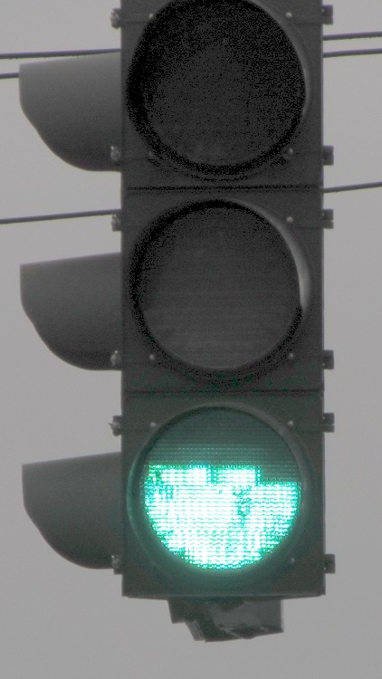
In our (admittedly limited) travels around New York State during the last half decade or so, I’ve seen many (as in, dozens of) traffic signals with this failure:
Apparently the topmost LED string burns out first, leaving the other two (?) strings intact. The earliest picture I have dates back to 2008, so this is a problem of long standing that’s probably wiped out any projected maintenance cost reduction for the entire purchase. The most recent failure I spotted, a few weeks after taking this picture, has a flickering upper string that means it’s not long for this world.
Somewhere up around Albany, I recently saw a green signal with only that string lit up and the other two (?) strings dead, but that’s the sole exception to the pattern.
Of late, NYS DOT has been installing a different green lamp with the LEDs in each string scattered over the entire surface and no diffuser. That means a failed string, of which I’ve already seen several examples in the area, darkens a few spots without being particularly obvious; a less common failure has a few flickering “pixels” that will eventually go dark. While that’s a net win, I wonder why only green lamps have this problem: we very rarely see red or amber lamps with any failed LEDs.
One red LED lamp down the road did fail spectacularly: the whole thing flashed, slowly and somewhat irregularly. Not a flicker, but a flash: long off and short on.
It’s hard to get pictures of failed traffic signals…
While I suppose I should report them, previous attempts to do so have only led to requests for the ID number of the traffic control box, which generally can’t be seen from the traffic lane. I am not stopping at an intersection, getting out, finding the box (perhaps crossing the intersection to get there), finding the ID number, and taking a picture for later reference; you know what happens to people who take pictures of infrastructure. You’d think the signals could phone home on their own, but they’re likely not connected.
You know how you’re supposed to not click on email links these days, even when they’re from “trustworthy” sources, because you might be a spear-phishing target? Well, here’s a true story about how our Credit Union handles the situation.
The backstory: I recently signed up for a service that provides an estimate of my credit score, which it does by asking the usual Big Three credit reporting agencies for my records on, presumably, a monthly basis. I’m not happy with that arrangement, but I wanted to see how well it worked and figured I’d cancel after a month or two. Based on these exchanges with their support staff, it’s time to cancel…
After I received the expected email from them, I discovered that the only way to reach the service was through an embedded link. I try to avoid doing that sort of thing, so I went directly to (what I assumed was) their website and tried to log in. That didn’t work, so I fired off a support message…
From me to CreditKarma:
Having signed up for your service through the Hudson Valley Federal Credit Union, it seems that I cannot sign on directly to your site using the email address and password I provided during the HVFCU signup.
That means the only way to sign on to my account requires clicking on the link provided in your monthly email, which redirects me through the HVFCU website.
Is that correct?
If so, how can I distinguish your email from a well-designed spear phishing attack that requires me to divulge two banking userids and passwords?
Thanks…
Their reply, which neatly avoids answering the questions:
Sorry for the confusion. Your HVFCU Credit Karma account is different from any account you may have created with www.CreditKarma.com. To log into your HVFCU Credit Karma account, you’ll first need to log into your online banking account and then log in through there.
But that’s not how it works:
OK, so I must go through the HVFCU website to reach you. That process seems to require cookies set by the redirection included in the email link, because simply signing on to the HVFCU website and clicking the appropriate link does not redirect to your website unless I have already followed the email link.
So, allow me to ask the key questions again:
The only way to sign on to my account requires clicking on the link provided in your monthly email, which redirects me through the HVFCU website.
Is that correct?
If so, how can I distinguish your email from a well-designed spear phishing attack that requires me to divulge two banking userids and passwords?
Please answer those questions, as I need to know how this works.
Thanks…
There’s been no answer after a week, so I think I’ve reached the end of their tech support.
Then I posed much the same question to the Credit Union:
Having recently signed up for the CreditKarma score monitoring service, I’m flabbergasted by the total lack of security awareness.
The only way to access the CreditKarma report is through the link in the monthly email. Clicking that link requires signing in to my HVFCU account, then to the CreditKarma account.
Without that clicking on that link, selecting the “Credit Score” menu item in the HVFCU site does nothing.
Without clicking on that link, the CreditKarma.com website does not recognize my email address.
How, exactly, can I distinguish that monthly email from a well-crafted spear phishing attack that will collect the userid and password for both of my accounts?
Is there an alternate procedure for accessing my CreditKarma account that does not require depending on a lengthy link contained in an email message?
Thanks…
Their reply seems slightly more informative, but note that they ignore the “must click the link” evidence I report and also avoid answering the hard questions:
I regret to hear of the difficulties you are experiencing with Credit Karma. If you would like to access the site directly, you should type: https://hvfcu.creditkarma.com. The https: indicates that the connection will be secured. “creditkarma.com” lets you know that you are connecting to Credit Karma’s web site. hvfcu. is the subdomain created by Credit Karma for HVFCU members. Your account will not work at http://www.creditkarma.com because the subdomain created for HVFCU is separate from their public site.
Additionally, you may also log on to Internet Banking, then click on the “My Credit Score” link near the top right of the page, and you may now log in. If you chose this option, ensure that all pop up blocker settings are adjusted since you will be required to access a separate web page. Clicking on the link in the monthly emails will direct you to the same place. We understand that you may not be comfortable clicking on a link or may be using a system or mobile device that doesn’t allow you to view the link, which would make it difficult to determine if a message was legitimate or fraudulent. In these cases, we recommend that you set a shortcut or favorite for https://hvfcu.creditkarma.com or else sign in to Internet Banking first, then click on the “My Credit Score” link.
So I tried again:
> Your account will not work at http://www.creditkarma.com because the subdomain created for HVFCU is separate from their public site.
Indeed, it doesn’t. When I asked them about that, their reply was, shall we say, unhelpful; they really want me to click on the link and didn’t even mention the HVFCU subdomain. I did tell them that I had an HVFCU account, so they weren’t completely ignorant of the situation.
They have not responded to my question about determining whether an email allegedly from them is a phishing attack, either.
> Additionally, you may also log on to Internet Banking, then click on the “My Credit Score” link near the top right of the page, and you may now log in.
As I reported, that doesn’t work unless you’ve previously clicked on the email link to set whatever tracking cookies they use. I’ve tried it immediately after clearing cookies and cache: it doesn’t work. Clicking on the link to bounce off their website sets everything up properly and then the HVFCU menu item works.
Try that and see how it works for you. I’d like to know whether it’s a peculiarity of Firefox and Chrome.
> We understand that you may not be comfortable clicking on a link
As the HVFCU page on phishing says: “Links within the email take you to a fake website that usually looks authentic because it uses graphics from the institution’s real website.” So, basically, I must regard all clickable links in all emails as suspect.
Given that the URL is total gibberish, with the both the HVFCU and Credit Karma URLs buried within tracking numbers, there’s no possibility of manually extracting and typing the address.
So, as I asked originally, please tell me exactly how I can tell that an email purporting to be from Credit Karma isn’t a very well-done phishing attack?
We both know there’s no way to do so, so why do you and Credit Karma rely on email links for such a vital function? You’re training your customers to click on emailed links, which is a terrible security practice for a bank.
Have you documented the direct sign-on process anywhere your customers can find it? I couldn’t, but maybe I’m not looking in the right place. Why not put those instructions in each email, rather than using clickable links?
Thanks…
Another week has passed, so I suspect they’re not going to answer those questions, either.
Am I the only person who thinks it’s bad practice for a bank to require you to click on emailed links?
This switch controlled an outlet, so I’m sure it’s hot-switched far too many vacuum cleaners, clothes irons, and suchlike over the last half century or so.
Our house is a bit fancier and originally had top-of-the-line mercury-wetted switches: the contacts sealed in the capsule don’t burn, but the springy supporting structures outside the capsule eventually wear out.
They’re still more reliable than X10 switches, though.
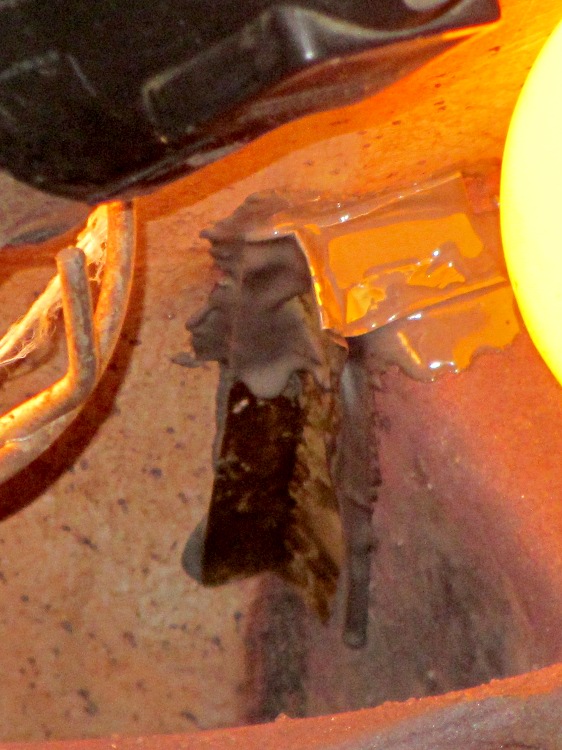
Which small spot on this hot-air furnace heat exchanger isn’t like all the other small spots?
Pinhole in furnace heat exchanger
Correct! The orange one at the corner of the rectangular exhaust gas flue that’s lit up like the sun, because you’re looking directly into the oil burner flame.
With the fire off and everything cooled down, it looked like this:
Pinhole in furnace heat exchanger – detail
Now, this calls for a new furnace (because replacing the heat exchanger costs as much as a new furnace), but as it turns out this was in an unoccupied house during the week before Christmas. So I scrubbed off the debris with a steel brush, bent up a snippet of 2 mil brass shimstock to fit the corner, applied a layer of JB Industro-Weld epoxy to the problem, and positioned 200 W of incandescent bulbs to help it cure slightly sooner than forever:
Furnace heat exchanger – temporary fix
That is most certainly not a final repair, not just because the heat exchanger’s normal operating temperature exceeds the epoxy’s 500 °F rating, but because where there’s one pinhole there’s bound to be more. The goal was to let us keep the furnace running until we could schedule the replacement after the holidays. Remember, the building isn’t occupied and neither of the smoke / CO detectors went off at any point in the proceedings.
Evidently, the beaver stopped just before the tree toppled, because the last cut looks very much like a chainsaw.
I didn’t spot their lodge out in the lake; they may have tucked it under the bank below the railroad bed.
If they keep this up, they’re sure to get trapped and moved somewhere they can’t interfere with our enjoyment of the natural landscape along the rail trail. [wince]
When the second hinge on my father-in-law’s scanner broke, he asked if I could fix it:
HP3970 Scanjet Lid – broken hinge
It’s a flatbed scanner, so the lid is nearly 18 inches long and weighs 2.2 pounds with the slide / negative backlight illuminator. The stress raiser notches, located exactly where the cracks started, look like a perfect example of how not to do these things.
I solvent-glued the hinges back together, with a square brass tube applying clamping force to the joint overnight, but this certainly won’t last for long:
HP3970 Scanjet Lid – crude repair
HP used to have some really smart engineers, but this looks like it was done by a Newkid (I was one, once, so I know the type) after a solid modeling and simulation session convinced him that those two thin plastic webs had enough strength for the job.
No. They. Do. Not.
Of course, HP provides no Official Way to repair that failure, as the hinges emerge seamlessly from the injection-molded plastic lid frame: you must scrap the scanner and buy a new one, because the lid would cost more than a new scanner. Equally of course, the fact that they don’t have a Windows driver beyond XP makes replacement a foregone conclusion.
It runs under Xubuntu 12.04, mostly, which is what I set him up with after the XP PC got compromised.
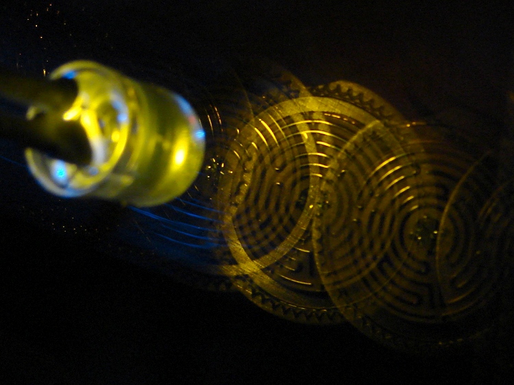
A bit of fiddling with the Arduino PWM hardware can turn a white LED into a stroboscopic tachometer to chop smooth motion into chunks:
Strobe – Maze 1 – 50 Hz 100 us
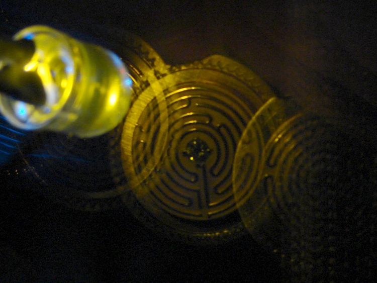
I was moving that pendant by hand and slight speed changes were easily visible:
Strobe – Maze 2 – 50 Hz 100 us
IBMers of a certain era may recognize the test object; the rest of you can go there.
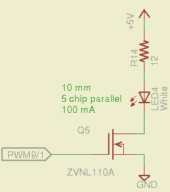
That’s a 10 mm warm-white LED with 5 parallel chips, running at about 100 mA from a 5 V supply, and driven from the same PWM channel and MOSFET that used to drive also drives the red channel of the RGB LED Mood Light:
White LED Strobe
The ZVNL110A MOSFET has a 3 Ω drain resistance, which becomes a significant part of the resistance; you’d want a bigger, better, lower resistance MOSFET to wring more light out of the LED. In fact, I ran the LED from 12 V with the same resistor at a few hundred mA.
The reason you need more light is to make up for the minuscule duty cycle. In order to “stop motion”, you want a very short pulse; I picked a 100 μs pulse. At 50 Hz, that works out to a 0.5% duty cycle: not much light at 100 mA, but OK for a demo.
You can’t do this with the standard Arduino PWM setup, because it produces a constant frequency (about 488 Hz) and varies the duty cycle; we need a variable frequency with a constant pulse length. Because a stroboscope needs fine-grained control over the frequency, in order to stop the motion of rotating objects, it should run from one of the 16 bit Timer1 PWM outputs, which means either PWM9 or PWM10. Note that simply changing the timer’s clock prescaler as described there won’t suffice, because that gives very coarse control of the PWM frequency.
It’s probably worth noting that trying to do precise timing purely in software with, say, the millis() and micros() functions, produces terrible results…
The Arduino timer hardware includes control over both the period and the duration of the output pulses. The Fine Manual describes all the timer configuration registers starting on page 109; see that post for a push-pull PWM driver that formed the basis of this one.
Fast PWM (Mode 14) has some useful characteristics:
Single-slope operation: timer counts only upward
Output PWM9 goes high when TCNT1 resets to 0
Output PWM9 goes low when TCNT1 = OCR1A
TCNT1 resets when TCNT1 = ICR1
The lowest possible output frequency occurs with ICR1 = 0xffff, so that Timer1 counts from 0x0000 to 0xffff before resetting (which, in that case, is indistinguishable from simply wrapping). The wrap period = ICR1 * tick period and the corresponding frequency = 1 / period.
The clock prescaler determines the overall range of Timer1 by setting the tick period. The Clock Select bit field can take on 6 useful, albeit widely separated, values (the other two select the external clock pin):
0 – stop timer
1 – prescale 1:1 = 62.5 ns tick → 244 Hz
2 – prescale 1:8 = 500 ns tick → 30 Hz
3 – prescale 1:64 = 4 μs tick → 3.8 Hz
4 – prescale 1:256 = 16 μs tick → 0.95 Hz
5 – prescale 1:1024 = 64 μs tick → 0.24 Hz
For my purposes, a lower limit around 4 Hz seemed about right. That means CS = 3, the prescaler runs at 1:64, and the timer ticks at 4 μs.
The frequency upper limit could be just under 1/(pulse width), which would produce a very high duty cycle. I arbitrarily set the limit to 1/(4 × pulse width), for a 25% duty cycle that works out to 1/(4 × 100 μs) = 2.5 kHz = 150 k flash/min. If you’re using very high current drive, then limit the duty cycle to prevent toasting the LED.
Because a strobe tach needs quick & easy adjustment, the encoder knob tweaks the pulse frequency in 1 Hz steps. Pushing the knob to close the shaft switch (if you have such a knob, of course, otherwise use another button; they all do the same thing here) reduces the step size to 0.01 Hz, which is more useful for fine tuning when you’re close to the goal. A real application requires better control over the numeric values (probably using integer values); I used floating point and simply ignored all the usual roundoff issues:
Shut off interrupts to prevent interference with the high byte storage register
Stop the timer: CS=0
Load the new upper limit in ICR1
Force TCNT1 to be just below IRC1 to terminate the current pulse
Start the timer: CS=3
Enable interrupts again
You’d probably plunk that into a separate function in a real program…
Printing the frequency becomes a hassle without floating point formatting in printf(). It should appear on the character LED display, too. Optionally / additionally showing the value in rev/min would be very nice.
You’d want to increment the frequency by some reasonable fraction of the current value, perhaps rounded to 1 / 2 / 5 / 10 percent steps. Larger steps by pushbutton? Truncate the current value to a multiple of the step size?
You would also want some way to adjust the flash duration, but that’s definitely in the nature of fine tuning.
As it stands, a 100 μs pulse really does stop motion:
Fan stopped at 2500 rpm
That’s a fan running at about 2500 rpm, with the LED flashing at 41.86 Hz. The camera exposure is 1/2 sec @ f/3.5, handheld, which means the camera integrated about 20 flashes. Ambient light accounts for the background blur: I boosted the grossly underexposed image right out of darkness. The square on the hub is retroreflective tape for a laser tachometer that verified the speed.
Yes, half a second handheld. The morning tea wears off during the day…
In round numbers, 41.86 Hz = 23.9 ms / rev. The fan diameter is 86 mm, so the blade tips travel 1.1 mm = (270 mm / 23.9 ms) × 100 μs during each flash. The tips seem slightly blurred when you (well, I) look very closely in real life, but I think this lashup worked pretty well right off the sketchpad.
The Arduino source code:
// Stroboscopic Tachometer
// Ed Nisley - KE4ANU - December 2012

//----------
// Pin assignments

const byte PIN_KNOB_A = 2;			// knob A switch - must be on ext interrupt 2
const byte PIN_KNOB_B = 4;			//  .. B switch
const byte PIN_BUTTONS = A5;		//  .. push-close momentary switches

const byte PIN_STROBE = 9;			// LED drive, must be PWM9 = OCR1A using Timer1

const byte PIN_PWM10 = 10;			// drivers for LED strip, must turn these off...
const byte PIN_PWM11 = 11;

const byte PIN_SYNC = 13;			// scope sync

//----------
// Constants

const int UPDATEMS = 10;				// update LEDs only this many ms apart

#define TCCRxB_CS 0x03					// Timer prescaler CS=3 -> 1:64 division

const float TICKPD = 64.0 * 62.5e-9;	// basic Timer1 tick rate: prescaler * clock

enum KNOB_STATES {KNOB_CLICK_0,KNOB_CLICK_1};

// ButtonThreshold must have N_BUTTONS elements, last = 1024

enum BUTTONS {SW_KNOB, B_1, B_2, B_3, B_4, N_BUTTONS};
const word ButtonThreshold[] = {265/2, (475+265)/2, (658+475)/2, (834+658)/2, (1023+834)/2, 1024};

//----------
// Globals

float FlashLength = 0.1e-3;						// strobe flash duration in seconds
word FlashLengthCt = FlashLength / TICKPD;		//  ... in Timer1 ticks

float FlashFreq = 20.0;							// strobe flash frequency in Hz
float FlashPd = 1.0 / FlashFreq;				//  ... period in sec
word FlashPdCt = FlashPd / TICKPD;				//  ... period in Timer1 ticks

float FreqIncr = 1.0;							// default frequency increment
const float FreqMin = 4.0;
const float FreqMax = 1.0/(4.0*FlashLength);

volatile char KnobCounter = 0;
volatile char KnobState;

byte Button, PrevButton;

unsigned long MillisNow;
unsigned long MillisThen;

//-- Helper routine for printf()

int s_putc(char c, FILE *t) {
  Serial.write(c);
}

//-- Knob interrupt handler

void KnobHandler(void)
{
	byte Inputs;
	Inputs = digitalRead(PIN_KNOB_B) << 1 | digitalRead(PIN_KNOB_A);  // align raw inputs
//	Inputs ^= 0x02;                             // fix direction

	switch (KnobState << 2 | Inputs) {
	case 0x00 : 				// 0 00 - glitch
        break;
	case 0x01 : 				 // 0 01 - UP to 1
        KnobCounter++;
		KnobState = KNOB_CLICK_1;
		break;
	case 0x03 : 				 // 0 11 - DOWN to 1
        KnobCounter--;
		KnobState = KNOB_CLICK_1;
		break;
	case 0x02 : 				 // 0 10 - glitch
        break;
	case 0x04 : 				 // 1 00 - DOWN to 0
        KnobCounter--;
		KnobState = KNOB_CLICK_0;
		break;
	case 0x05 : 				 // 1 01 - glitch
        break;
	case 0x07 : 				 // 1 11 - glitch
        break;
	case 0x06 : 				 // 1 10 - UP to 0
        KnobCounter++;
		KnobState = KNOB_CLICK_0;
		break;
	default :  					// something is broken!
        KnobCounter = 0;
		KnobState = KNOB_CLICK_0;
	}
}

//-- Read and decipher analog switch inputs
//		returns N_BUTTONS if no buttons pressed

byte ReadButtons(int PinNumber) {

word RawButton;
byte ButtonNum;

	RawButton = analogRead(PinNumber);

	for (ButtonNum = 0; ButtonNum <= N_BUTTONS; ButtonNum++){
		if (RawButton < ButtonThreshold[ButtonNum])
			break;
	}

	return ButtonNum;

}

//------------------
// Set things up

void setup() {
	pinMode(PIN_SYNC,OUTPUT);
	digitalWrite(PIN_SYNC,LOW);	// show we arrived

	analogWrite(PIN_PWM10,0);			// turn off other PWM outputs
	analogWrite(PIN_PWM11,0);

	analogWrite(PIN_STROBE,1);			// let Arduino set up default Timer1 PWM
	TCCR1B = 0;							// turn off Timer1 for strobe setup
	TCCR1A = 0x82;						// clear OCR1A on match, Fast PWM, lower WGM1x = 14
	ICR1 = FlashPdCt;
	OCR1A = FlashLengthCt;
	TCNT1 = FlashLengthCt - 1;
	TCCR1B = 0x18 | TCCRxB_CS;			// upper WGM1x = 14, Prescale 1:64, start Timer1

	pinMode(PIN_KNOB_B,INPUT_PULLUP);
	pinMode(PIN_KNOB_A,INPUT_PULLUP);

	KnobState = digitalRead(PIN_KNOB_A);
	Button = PrevButton = ReadButtons(PIN_BUTTONS);

	attachInterrupt((PIN_KNOB_A - 2),KnobHandler,CHANGE);

	Serial.begin(9600);
	fdevopen(&s_putc,0);				// set up serial output for printf()

	printf("Stroboscope Tachometer\r\nEd Nisley - KE4ZNU - December 2012\r\n");

	printf("Frequency: %d.%02d\nPulse duration: %d us\n",
		   (int)FlashFreq,(int)(100.0 * (FlashFreq - trunc(FlashFreq))),
		   (int)(1e6 * FlashLength));

	MillisThen = millis();

}

//------------------
// Run the test loop

void loop() {

	MillisNow = millis();

	if ((MillisNow - MillisThen) > UPDATEMS) {

		digitalWrite(PIN_SYNC,HIGH);

		Button = ReadButtons(PIN_BUTTONS);
		if (PrevButton != Button) {
			if (Button == N_BUTTONS) {
//				printf("Button %d released\n",PrevButton);
				FreqIncr = 1.0;
			}
			else
//				printf("Button %d pressed\n",Button);
//				if (Button == SW_KNOB)
					FreqIncr = 0.01;
			PrevButton = Button;
		}

		if (KnobCounter) {
			FlashFreq += (float)KnobCounter * FreqIncr;
			KnobCounter = 0;

			FlashFreq = constrain(FlashFreq,FreqMin,FreqMax);
			FlashFreq = round(100.0 * FlashFreq) / 100.0;

			FlashPd = 1.0 / FlashFreq;
			FlashPdCt = FlashPd / TICKPD;

			noInterrupts();
			TCCR1B &= 0xf8;				// stop Timer1
			ICR1 = FlashPdCt;			// set new period
			TCNT1 = FlashPdCt - 1;		// force immediate update
			TCCR1B |= TCCRxB_CS;		// start Timer1
			interrupts();

			printf("Frequency: %d.%02d\n",
				   (int)FlashFreq,(int)(100.0 * (FlashFreq - trunc(FlashFreq))));
		}

		digitalWrite(PIN_SYNC,LOW);

		MillisThen = MillisNow;
	}

}
That’s a grandiose name for a blinking LED, if I ever saw one…