Running ten random red LEDs (taken from the bag of 100 sent halfway around the planet) through the LED Curver Tracer produces this plot:
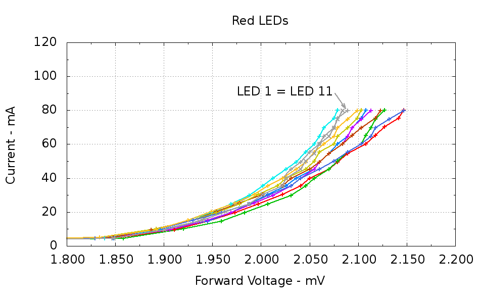
The two gray traces both come from LED 1 to verify that the process produces the same answer for the same LED. It does, pretty much.
Repeating that with the same LEDs in the same order, but stepping 10 mA up to 100 mA produces a similar plot:
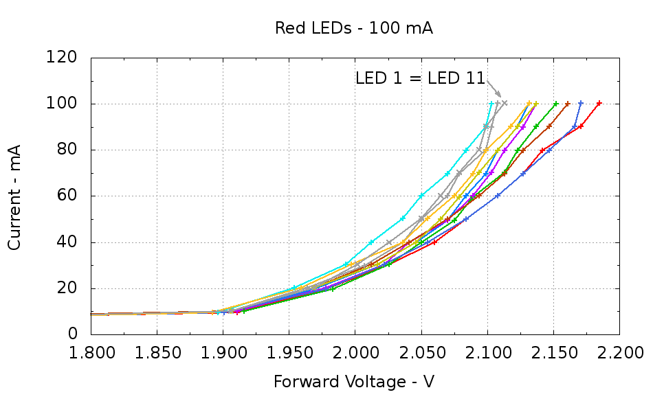
The voltage quantization comes from the Arduino’s 5 mV ADC resolution (the readings are averaged, but there’s actually not much noise) and the current quantization comes from the step value in the measurement loop (5 mA in the first plot, 10 mA in the second). Seeing the LEDs line up mostly the same way at 80 mA in both graphs is comforting, as it suggests the measurement results aren’t completely random numbers.
Apply this bit of Bash-fu to the dataset file:
seq 1 11 > /tmp/seq.txt ; grep -E "^100" Red\ LEDs\ -\ 100\ mA.csv | cut -f 2,5 | paste /tmp/seq.txt - > "Red LED Vf at 100 mA.csv"
Produces a numbered listing of the LED current (in μA) and voltage (in mV) at a nominal 100 mA for each LED:
1	100415	2108
2	100415	2185
3	99957	2152
4	100415	2132
5	99957	2137
6	99957	2103
7	99957	2161
8	99957	2137
9	100415	2171
10	100415	2132
11	100415	2113
Putting three red LEDs in series could produce a total forward drop anywhere between 6.309 V (3*2.103) and 6.555 V (3*2.185), a difference of nigh onto a quarter volt, if you assume this group spans the entire range of voltages and the whole collection has many duplicate values and you’re remarkably unlucky while picking LEDs. For this particular set, however, summing three successive groups of three produces 6.445, 6.372, and 6.469 V, for a spread of just under 100 mV. That suggests it’s probably not worthwhile to select LEDs for forward voltage within each series group of three, although matching parallel LEDs makes a lot of sense. I have no confidence the values will remain stable over power-on hours / thermal cycling / current stress.
The capacity plot for the Wouxun KG-UV3D lithium battery packs shows that there’s not a lot of capacity left after 7.0 V, so shutting down or scaling back to lower current wouldn’t be a major loss. However, it’s not clear a fixed resistor will do a sufficient job of current limiting with 6.5 V forward voltage across the LED string:
- At 7.5 V, 100 mA calls for 10 Ω (drop 1 V at 100 mA)
- At 8.2 V, 10 Ω produces 170 mA (1.7 V across 10 Ω)
- At 7.0 V, 10 Ω produces 50 mA (0.5 V across 10 Ω)
Obviously, 170 mA is way too much, even by my lax standards.
A 100 mV variation in forward voltage between stacks, each with a 10 Ω resistor, translates into about 10 mA difference in current. This may actually call for current sensors and direct current control, although using a sensor per string, seems excessive. Low dropout regulators in current-source mode might suffice, but that still seems messy.
The test rig will run from a hard 7.5 V supply, which means I can use fixed resistors and be done with it.
The raw data behind those graphs, with LED 1 and LED 11 being the same LED:
# LED Curve Tracer
# Ed Nisley - KE4ZNU - December 2012
# VCC at LED: 4877 mV
# Bandgap reference voltage: 1039 mV

# Insert LED, press button 1 to start...
# INOM	ILED	VccLED	VD	VLED	VG	VS	VGS	VDS	<--- LED 1
0	0	4877	3707	1169	0	0	0	3707
10	10087	4877	2970	1906	2084	105	1978	2864
20	20174	4872	2907	1964	2262	211	2050	2696
30	29803	4877	2869	2007	2412	312	2099	2556
40	39891	4877	2840	2036	2546	418	2127	2421
50	49978	4872	2821	2050	2681	524	2156	2296
60	60066	4877	2806	2070	2816	630	2185	2176
70	69694	4872	2792	2079	2927	731	2195	2060
80	80240	4877	2777	2099	3071	842	2229	1935
90	89869	4872	2768	2103	3196	943	2253	1824
100	100415	4872	2763	2108	3312	1054	2257	1709

# Insert LED, press button 1 to start...
# INOM	ILED	VccLED	VD	VLED	VG	VS	VGS	VDS	<--- LED 2
0	0	4877	3803	1073	0	0	0	3803
10	9628	4872	2960	1911	2084	101	1983	2859
20	19716	4877	2898	1978	2257	207	2050	2691
30	30262	4877	2850	2026	2421	317	2103	2532
40	39891	4877	2816	2060	2551	418	2132	2397
50	49978	4872	2787	2084	2686	524	2161	2262
60	60066	4872	2763	2108	2816	630	2185	2132
70	69694	4872	2744	2127	2927	731	2195	2012
80	79782	4872	2729	2142	3052	837	2214	1892
90	90328	4872	2700	2171	3191	948	2243	1752
100	100415	4872	2686	2185	3331	1054	2277	1632

# Insert LED, press button 1 to start...
# INOM	ILED	VccLED	VD	VLED	VG	VS	VGS	VDS	<--- LED 3
0	0	4877	3716	1160	0	0	0	3716
10	10087	4877	2960	1916	2094	105	1988	2854
20	19716	4877	2893	1983	2257	207	2050	2686
30	30262	4877	2850	2026	2416	317	2099	2532
40	39891	4872	2821	2050	2546	418	2127	2402
50	49520	4872	2797	2075	2681	519	2161	2277
60	59607	4872	2782	2089	2802	625	2176	2156
70	70153	4877	2763	2113	2932	736	2195	2026
80	79782	4872	2749	2123	3076	837	2238	1911
90	90328	4872	2734	2137	3182	948	2233	1786
100	99957	4872	2720	2152	3321	1049	2272	1670

# Insert LED, press button 1 to start...
# INOM	ILED	VccLED	VD	VLED	VG	VS	VGS	VDS	<--- LED 4
0	0	4877	3716	1160	0	0	0	3716
10	10087	4877	2965	1911	2079	105	1973	2859
20	19716	4872	2903	1969	2253	207	2046	2696
30	30262	4877	2859	2017	2407	317	2089	2542
40	39891	4877	2830	2046	2546	418	2127	2412
50	49520	4877	2806	2070	2686	519	2166	2286
60	60066	4872	2787	2084	2821	630	2190	2156
70	69694	4872	2773	2099	2927	731	2195	2041
80	79782	4872	2763	2108	3052	837	2214	1925
90	90328	4872	2749	2123	3196	948	2248	1800
100	100415	4872	2739	2132	3331	1054	2277	1685

# Insert LED, press button 1 to start...
# INOM	ILED	VccLED	VD	VLED	VG	VS	VGS	VDS	<--- LED 5
0	0	4877	3697	1179	0	0	0	3697
10	10087	4877	2965	1911	2079	105	1973	2859
20	20174	4877	2898	1978	2257	211	2046	2686
30	30262	4877	2854	2022	2412	317	2094	2537
40	39891	4872	2830	2041	2551	418	2132	2412
50	49520	4872	2802	2070	2681	519	2161	2282
60	60066	4877	2787	2089	2816	630	2185	2156
70	70153	4872	2768	2103	2932	736	2195	2031
80	79782	4872	2758	2113	3071	837	2233	1920
90	89869	4872	2744	2127	3177	943	2233	1800
100	99957	4872	2734	2137	3293	1049	2243	1685

# Insert LED, press button 1 to start...
# INOM	ILED	VccLED	VD	VLED	VG	VS	VGS	VDS	<--- LED 6
0	0	4877	3764	1112	0	0	0	3764
10	9628	4877	2980	1896	2079	101	1978	2879
20	20174	4877	2922	1954	2262	211	2050	2710
30	30262	4877	2883	1993	2412	317	2094	2566
40	39891	4872	2859	2012	2551	418	2132	2440
50	50437	4872	2835	2036	2686	529	2156	2306
60	60066	4872	2821	2050	2816	630	2185	2190
70	69694	4872	2802	2070	2941	731	2209	2070
80	79782	4872	2787	2084	3081	837	2243	1949
90	90328	4872	2773	2099	3191	948	2243	1824
100	99957	4872	2768	2103	3307	1049	2257	1718

# Insert LED, press button 1 to start...
# INOM	ILED	VccLED	VD	VLED	VG	VS	VGS	VDS	<--- LED 7
0	0	4877	3870	1006	0	0	0	3870
10	10087	4877	2970	1906	2089	105	1983	2864
20	20174	4877	2907	1969	2262	211	2050	2696
30	30262	4872	2859	2012	2412	317	2094	2542
40	39891	4872	2830	2041	2551	418	2132	2412
50	49978	4872	2802	2070	2686	524	2161	2277
60	60066	4872	2777	2094	2821	630	2190	2147
70	69694	4872	2758	2113	2927	731	2195	2026
80	79782	4872	2744	2127	3052	837	2214	1906
90	90328	4872	2724	2147	3196	948	2248	1776
100	99957	4872	2710	2161	3302	1049	2253	1660

# Insert LED, press button 1 to start...
# INOM	ILED	VccLED	VD	VLED	VG	VS	VGS	VDS	<--- LED 8
0	0	4877	3702	1174	0	0	0	3702
10	10087	4877	2970	1906	2084	105	1978	2864
20	20174	4872	2903	1969	2262	211	2050	2691
30	30262	4877	2859	2017	2412	317	2094	2542
40	39891	4877	2830	2046	2546	418	2127	2412
50	49978	4872	2806	2065	2676	524	2152	2282
60	59607	4872	2792	2079	2802	625	2176	2166
70	70153	4872	2777	2094	2932	736	2195	2041
80	79782	4872	2763	2108	3076	837	2238	1925
90	90328	4872	2749	2123	3196	948	2248	1800
100	99957	4872	2734	2137	3302	1049	2253	1685

# Insert LED, press button 1 to start...
# INOM	ILED	VccLED	VD	VLED	VG	VS	VGS	VDS	<--- LED 9
0	0	4872	3721	1150	0	0	0	3721
10	9628	4877	2975	1901	2084	101	1983	2874
20	19716	4877	2898	1978	2257	207	2050	2691
30	30262	4877	2854	2022	2407	317	2089	2537
40	39891	4877	2821	2055	2546	418	2127	2402
50	49978	4872	2787	2084	2686	524	2161	2262
60	60066	4872	2763	2108	2821	630	2190	2132
70	69694	4872	2744	2127	2927	731	2195	2012
80	79782	4872	2724	2147	3052	837	2214	1887
90	90328	4872	2705	2166	3196	948	2248	1757
100	100415	4872	2700	2171	3297	1054	2243	1646

# Insert LED, press button 1 to start...
# INOM	ILED	VccLED	VD	VLED	VG	VS	VGS	VDS	<--- LED 10
0	0	4872	3702	1169	0	0	0	3702
10	9628	4872	2980	1892	2070	101	1969	2879
20	20174	4872	2912	1959	2253	211	2041	2700
30	30262	4872	2874	1997	2412	317	2094	2556
40	39891	4877	2840	2036	2546	418	2127	2421
50	50437	4877	2821	2055	2691	529	2161	2291
60	60066	4877	2802	2075	2816	630	2185	2171
70	69694	4872	2782	2089	2927	731	2195	2050
80	79782	4872	2773	2099	3052	837	2214	1935
90	90328	4872	2753	2118	3182	948	2233	1805
100	100415	4872	2739	2132	3331	1054	2277	1685

# Insert LED, press button 1 to start...
# INOM	ILED	VccLED	VD	VLED	VG	VS	VGS	VDS	<--- LED 11
0	0	4877	3707	1169	0	0	0	3707
10	10087	4877	2970	1906	2084	105	1978	2864
20	20174	4877	2907	1969	2257	211	2046	2696
30	30262	4872	2869	2002	2412	317	2094	2551
40	39891	4872	2845	2026	2546	418	2127	2426
50	50437	4872	2821	2050	2686	529	2156	2291
60	60066	4872	2806	2065	2821	630	2190	2176
70	70153	4872	2792	2079	2941	736	2205	2055
80	80240	4872	2777	2094	3061	842	2219	1935
90	90328	4872	2773	2099	3187	948	2238	1824
100	100415	4872	2758	2113	3317	1054	2262	1704

# Insert LED, press button 1 to start...
The Bash / Gnuplot script that produces them:
#!/bin/sh
#-- overhead
export GDFONTPATH="/usr/share/fonts/truetype/"
base="${1%.*}"
echo Base name: ${base}
ofile=${base}.png
echo Input file: $1
echo Output file: ${ofile}
#-- do it
gnuplot << EOF
#set term x11
set term png font "arialbd.ttf" 18 size 950,600
set output "${ofile}"
set title "${base}"
set key noautotitles
unset mouse
set bmargin 4
set grid xtics ytics
set xlabel "Forward Voltage - V"
set format x "%6.3f"
set xrange [1.8:2.2]
#set xtics 0,5
set mxtics 2
#set logscale y
#set ytics nomirror autofreq
set ylabel "Current - mA"
set format y "%4.0f"
set yrange [0:120]
set mytics 2
#set y2label "right side variable"
#set y2tics nomirror autofreq 2
#set format y2 "%3.0f"
#set y2range [0:200]
#set y2tics 32
#set rmargin 9
set datafile separator "\t"
set label 1 "LED 1 = LED 11" at 2.100,110 right font "arialbd,18"
set arrow from 2.100,110 to 2.110,103 lt 1 lw 2 lc 0
plot    \
"$1" index 0:9 using (\$5/1000):(\$2/1000):(column(-2)) with linespoints lw 2 lc variable,\
"$1" index 10 using (\$5/1000):(\$2/1000) with linespoints lw 2 lc 0
EOF
And the Arduino source code, which bears a remarkable resemblance to the original firmware:
// LED Curve Tracer
// Ed Nisley - KE4ANU - December 2012

#include <stdio.h>

//----------
// Pin assignments

const byte PIN_READ_LEDSUPPLY = 0;    // AI - LED supply voltage        blue
const byte PIN_READ_VDRAIN = 1;        // AI - drain voltage            red
const byte PIN_READ_VSOURCE = 2;    // AI - source voltage            orange
const byte PIN_READ_VGATE = 3;        // AI - VGS after filtering        violet

const byte PIN_SET_VGATE = 11;        // PWM - gate voltage            brown

const byte PIN_BUTTON1 = 8;            // DI - button to start tests    green
const byte PIN_BUTTON2 = 7;            // DI - button for options        yellow

const byte PIN_HEARTBEAT = 13;        // DO - Arduino LED
const byte PIN_SYNC = 2;            // DO - scope sync output

//----------
// Constants

const int MaxCurrent = 100;                // maximum LED current - mA
const int ISTEP = 10;                    // LED current increment

const float Vcc = 4.930;                // Arduino supply -- must be measured!

const float RSense = 10.500;            // current sense resistor

const float ITolerance = 0.0005;        // current setpoint tolerance

const float VGStep = 0.019;                // increment/decrement VGate = 5 V / 256

const byte PWM_Settle = 5;                // PWM settling time ms

#define TCCRxB 0x01                        // Timer prescaler = 1:1 for 32 kHz PWM

#define MK_UL(fl,sc) ((unsigned long)((fl)*(sc)))
#define MK_U(fl,sc) ((unsigned int)((fl)*(sc)))

//----------
// Globals

float AVRef1V1;                    // 1.1 V bandgap reference - calculated from Vcc

float VccLED;                    // LED high-side supply

float VDrain;                    // MOSFET terminal voltages
float VSource;
float VGate;

unsigned int TestNum = 1;

long unsigned long MillisNow;

//-- Read AI channel
//      averages several readings to improve noise performance
//        returns value in mV assuming VCC ref voltage

#define NUM_T_SAMPLES    10

float ReadAI(byte PinNum) {

word RawAverage;

digitalWrite(PIN_SYNC,HIGH);                // scope sync

RawAverage = analogRead(PinNum);            // prime the averaging pump

for (int i=2; i <= NUM_T_SAMPLES; i++) {
RawAverage += (word)analogRead(PinNum);
}

digitalWrite(PIN_SYNC,LOW);

RawAverage /= NUM_T_SAMPLES;

return Vcc * (float)RawAverage / 1024.0;

}

//-- Set PWM output

void SetPWMVoltage(byte PinNum,float PWMVolt) {

byte PWM;

PWM = (byte)(PWMVolt / Vcc * 255.0);

analogWrite(PinNum,PWM);
delay(PWM_Settle);

}

//-- Set VGS to produce desired LED current
//        bails out if VDS drops below a sensible value

void SetLEDCurrent(float ITarget) {

float ISense;                // measured current
float VGateSet;            // output voltage setpoint
float IError;                // (actual - desired) current

VGate = ReadAI(PIN_READ_VGATE);                    // get gate voltage
VGateSet = VGate;                                    //  because input may not match output

do {

VSource = ReadAI(PIN_READ_VSOURCE);
ISense = VSource / RSense;                        // get LED current

//    printf("\r\nITarget: %lu mA",MK_UL(ITarget,1000.0));
IError = ISense - ITarget;

//    printf("\r\nISense: %d mA VGateSet: %d mV VGate %d IError %d mA",
//           MK_U(ISense,1000.0),
//           MK_U(VGateSet,1000.0),
//           MK_U(VGate,1000.0),
//           MK_U(IError,1000.0));

if (IError < -ITolerance) {
VGateSet += VGStep;
//      Serial.print('+');
}
else if (IError > ITolerance) {
VGateSet -= VGStep;
//      Serial.print('-');
}

VGateSet = constrain(VGateSet,0.0,Vcc);
SetPWMVoltage(PIN_SET_VGATE,VGateSet);

VDrain = ReadAI(PIN_READ_VDRAIN);        // sample these for the main loop
VGate = ReadAI(PIN_READ_VGATE);
VccLED = ReadAI(PIN_READ_LEDSUPPLY);

if ((VDrain - VSource) < 0.020) {            // bail if VDS gets too low
printf("# VDS=%d too low, bailing\r\n",MK_U(VDrain - VSource,1000.0));
break;
}

} while (abs(IError) > ITolerance);

//    Serial.println(" Done");
}

//-- compute actual 1.1 V bandgap reference based on known VCC = AVcc (more or less)
//        adapted from http://code.google.com/p/tinkerit/wiki/SecretVoltmeter

float ReadBandGap(void) {

word ADCBits;
float VBandGap;

ADMUX = _BV(REFS0) | _BV(MUX3) | _BV(MUX2) | _BV(MUX1);    // select 1.1 V input
delay(2); // Wait for Vref to settle

ADCSRA |= _BV(ADSC);                                        // Convert
while (bit_is_set(ADCSRA,ADSC));

ADCBits = ADCL;
ADCBits |= ADCH<<8;

VBandGap = Vcc * (float)ADCBits / 1024.0;
return VBandGap;
}

//-- Print message, wait for a given button press

void WaitButton(int Button,char *pMsg) {
printf("# %s",pMsg);
while(HIGH == digitalRead(Button)) {
delay(100);
digitalWrite(PIN_HEARTBEAT,!digitalRead(PIN_HEARTBEAT));
}

delay(50);                // wait for bounce to settle
digitalWrite(PIN_HEARTBEAT,LOW);
}

//-- Helper routine for printf()

int s_putc(char c, FILE *t) {
Serial.write(c);
}

//------------------
// Set things up

void setup() {
pinMode(PIN_HEARTBEAT,OUTPUT);
digitalWrite(PIN_HEARTBEAT,LOW);    // show we arrived

pinMode(PIN_SYNC,OUTPUT);
digitalWrite(PIN_SYNC,LOW);        // show we arrived

TCCR1B = TCCRxB;                    // set frequency for PWM 9 & 10
TCCR2B = TCCRxB;                    // set frequency for PWM 3 & 11

pinMode(PIN_SET_VGATE,OUTPUT);
analogWrite(PIN_SET_VGATE,0);        // force gate voltage = 0

pinMode(PIN_BUTTON1,INPUT_PULLUP);    // use internal pullup for buttons
pinMode(PIN_BUTTON2,INPUT_PULLUP);

Serial.begin(9600);
fdevopen(&s_putc,0);                // set up serial output for printf()

printf("# LED Curve Tracer\r\n# Ed Nisley - KE4ZNU - December 2012\r\n");

VccLED = ReadAI(PIN_READ_LEDSUPPLY);
printf("# VCC at LED: %d mV\r\n",MK_U(VccLED,1000.0));

AVRef1V1 = ReadBandGap();            // compute actual bandgap reference voltage
printf("# Bandgap reference voltage: %lu mV\r\n",MK_UL(AVRef1V1,1000.0));

}

//------------------
// Run the test loop

void loop() {

Serial.println('\n');                        // blank line for Gnuplot indexing

WaitButton(PIN_BUTTON1,"Insert LED, press button 1 to start...\r\n");
printf("# INOM\tILED\tVccLED\tVD\tVLED\tVG\tVS\tVGS\tVDS\t<--- LED %d\r\n",TestNum++);
digitalWrite(PIN_HEARTBEAT,LOW);

for (int ILED=0; ILED <= MaxCurrent; ILED+=ISTEP) {
SetLEDCurrent(((float)ILED)/1000.0);
printf("%d\t%lu\t%d\t%d\t%d\t%d\t%d\t%d\t%d\r\n",
ILED,
MK_UL(VSource / RSense,1.0e6),
MK_U(VccLED,1000.0),
MK_U(VDrain,1000.0),
MK_U(VccLED - VDrain,1000.0),
MK_U(VGate,1000.0),
MK_U(VSource,1000.0),
MK_U(VGate - VSource,1000),
MK_U(VDrain - VSource,1000.0)
);
}

SetPWMVoltage(PIN_SET_VGATE,0.0);

}

Comments
4 responses to “Red LEDs: Current vs. Voltage Sorting”
Why not use a constant current switcher made for LEDs? Or boost the battery voltage up to where all the LEDs can be in a single series string, combined with a current limiting resistor?
It may come down to that… [grin]
I want several strings, which would require a current-controlled switcher for each string. Because I only need two or three of these lights, I’m thinking I can mix-and-match some LEDs so the strings share the current equitably. Might not work, but it’ll be interesting to find out why or why not.
The great thing about a current-control driver is that you don’t need a ballast resistor. It generally does, however, require a current-sense resistor, which I’d like to avoid. Eliminating the sense resistor would allow operation with less margin between the battery voltage and the LED forward drop; ideally, the MOSFET doing the switching could also serve as the current limiter, right down to the point where the MOSFET on-resistance becomes the limiting issue.
That’s why I doodled up those notes on a Hall effect current sensor… it might come in handy some day!
[…] « Red LEDs: Current vs. Voltage Sorting […]
[…] nearly indistinguishable from the red LEDs. […]