Ed Nisley's Blog: Shop notes, electronics, firmware, machinery, 3D printing, laser cuttery, and curiosities. Contents: 100% human thinking, 0% AI slop.
The HRECOS folks installed a display on the Walkway Over the Hudson that shows current environmental conditions at the river sampling station just north of the bridge:
HRECOS Display with internal condensation
Those two blurry white rectangles are paper charts taped to the inside of the case below the scrolling LED display, so I think they’re discovering what happens when you trap ambient air inside a sealed enclosure without dehumidification. Even if they weren’t opening the case every now and again to change the charts, diurnal pumping would pull outside air past any affordable non-hermetic seal.
That fancy electronics won’t last long under those conditions; I foresee several pounds of silica gel in their future…
The whole point of the new guide tube block is to see if a larger ID tube will reduce the force required to pull the filament through it; long after Dan suggested simply using a larger tube, I got around to picking up a lifetime supply of 1/4 inch OD polyethylene tubing: 25 feet for $3. The ID is about 0.17 inch = 4.3 mm, large enough to let the 1.75 mm filament move smoothly, and the inside clearance provides a few millimeters of free motion so that retraction moves don’t require pushing the guide tube around.
The new filament guide + wire cover anchors the spool end of the tube:
M2 Larger Filament Guide – overview
On the other end, I blobbed a piece of 1/4 inch ID tubing to anchor the guide tube. It’s nicer than the twist of cardboard I used before, but nothing to get excited about:
As I hoped, the larger guide tube reduces the force required to pull the filament into the extruder under 1 pound. Most of that force comes from persuading the filament spool to drag-rotate around the plastic support arm, so some simple improvements should help there, as well. I foresee some bearings in its future.
Fine tuning of the tubing length is also in order, but that’ll require more printing sessions.
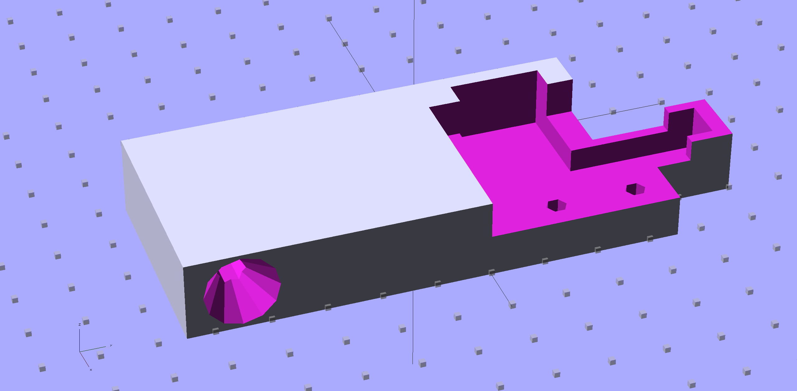
With the reverse-engineered wire cover model in hand, a bit of tinkering extends one side into a relentlessly rectangular block with a hole for the filament guide tube:
M2 Wire Cover Filament Guide – overview
Because the block sits somewhat to the rear of the spool, I added a conical entrance to help ease the filament around the corner into the tube. The hole fits the larger 1/4 inch tube that I’m trying out, with a stop equal to the tube’s 0.17 inch ID just before the conical section, as shown in this cross-section view:
M2 Wire Cover Filament Guide – guide tube section
It fits just about the way you’d expect:
M2 Larger Filament Guide – rear view
The perspective makes the guide tube look more angled than it really is; most of that curve is toward the front, so it’s considerably foreshortened in this view.
The metal bar with the cross pin sticking up in front is a bar clamp that holds an oak strip across the back of the bench to keep the M2 from walking away.
The OpenSCAD source code:
// Improved M2 filament guide and X-min switch wire guide
// Ed Nisley KE4ZNU - Oct 2013

Layout = "Build";				// Build Section

//- Useful Stuff

function IntegerMultiple(Size,Unit) = Unit * ceil(Size / Unit);

Protrusion = 0.1;

HoleWindage = 0.2;

//- Sizes

PlateMinThick = 8.0;				// basic thickness excluding wire guides
PlateLength = 55.0;					// from side of frame beyond top wire guide

TopGuideLength = 7.0;				// protrusion from plate

PlateThick = PlateMinThick + TopGuideLength;

echo(str("Total thickness: ",PlateThick));

GuideTubeOD = 6.3;					// max diameter!
GuideTubeID = 4.3;					// max diameter!
GuideTubeOffset = 45.0;				// centerline from edge of frame

//- Adjust hole diameter to make the size come out right

module PolyCyl(Dia,Height,ForceSides=0) {			// based on nophead's polyholes

  Sides = (ForceSides != 0) ? ForceSides : (ceil(Dia) + 2);

  FixDia = Dia / cos(180/Sides);

  cylinder(r=(FixDia + HoleWindage)/2,h=Height,$fn=Sides);
}

//- Put peg grid on build surface

module ShowPegGrid(Space = 10.0,Size = 1.0) {

  RangeX = floor(100 / Space);
  RangeY = floor(125 / Space);

	for (x=[-RangeX:RangeX])
	  for (y=[-RangeY:RangeY])
		translate([x*Space,y*Space,Size/2])
		  %cube(Size,center=true);

}

//- Define basic block shape
//  Mostly reverse engineered from
//    https://github.com/MakerGear/M2/blob/master/Printed%20Parts/STL/M2%20X%20Endstop%20Wire%20Cover%20with%20Filament%20Guide.stl
//	Hence all the magic numbers...

module BaseBlock() {

SideGuideLength = 4.0;				// protrusion = even with frame interior
ChannelDepth = 4.5;					// wiring channel
FrameOffset = 28;

	translate([18,28,0]) {			// align neatly for later processing

		if (true)
			color("Green",0.2)
				translate([-18,22,15])
					rotate([-90,0,-90])
						import("file:///mnt/bulkdata/Project%20Files/Thing-O-Matic/M2%20Parts/Filament%20Guide/M2+X+Endstop+Wire+Cover+with+Filament+Guide.stl",
								convexity=10);

		difference() {
			linear_extrude(height=PlateThick,convexity=5)		// main block
				polygon(points=[[0,0],[0,22],[12,22],[12,7.5],[22,7.5],
								[22,-(PlateLength + FrameOffset)],[-18,-(PlateLength + FrameOffset)],
								[-18,0]
						]);

			for (i=[-1,0])
				translate([17,((i*15.0)+ 1.05),-Protrusion])
					rotate(180/6) {
						PolyCyl(3.1,(PlateMinThick + 2*Protrusion),6);		// screw holes
						PolyCyl(5.7,(3.0 + Protrusion),6);					//  ... countersink
					}

			translate([0,0,(PlateMinThick - ChannelDepth)])		// wire channel
				linear_extrude(height=15,convexity=5)
					polygon(points=[[2,-5],[2,19],[10,19],[10,-22],[-15,-22],[-15,-5]
							]);

			translate([-10,14,PlateMinThick])				// M2 frame
				rotate(-90)
					cube([42,35,10],center=false);

			translate([-5,5,(PlateMinThick + SideGuideLength)])	// shorten side guide
				cube([20,20,10],center="false");
		}
	}
}

//- Complete object

module GuideCover() {

	difference() {
		BaseBlock();

		translate([50,-GuideTubeOffset,PlateThick/2])
			rotate([0,-90,0])
				rotate(180/6)
					PolyCyl(GuideTubeID,60,6);

		translate([25,-GuideTubeOffset,PlateThick/2])
			rotate([0,-90,0])
				rotate(180/6)
					PolyCyl(GuideTubeOD,60,6);

		translate([41,-GuideTubeOffset,PlateThick/2])
			rotate([0,-90,0])
				rotate(180/6)
					cylinder(r1= 0.5*PlateThick,r2=GuideTubeID/2,h=8,$fn=12);
	}
}

//- Build it

ShowPegGrid();

if (Layout == "Section")
	difference() {
		GuideCover();
		translate([2*100/3,-GuideTubeOffset,-PlateThick])
			rotate(180)
				cube([100,PlateLength,3*PlateThick]);
	}

if (Layout == "Build")
	GuideCover();
Mary volunteered me as a “white glove” helper: we walked the show floor for a few hours wearing cute aprons and white knit gloves.
Rule Zero: nobody touches the quilts. When people wanted to see the back side, we did all the handling. This worked out quite well; pretty nearly everybody understood what was going on, although we all agreed that fine quilts exhibit a magnetic attraction to fingertips.
Pro tip I: when the sign at the entrance says NO DRINKS, that means your coffee isn’t allowed in the exhibit area. You may be a special person, but you’re not that special. We’re not picking on you.
Pro tip II: when you bring your brat to a quilt show and let the kid dive under frames holding quilts representing thousands of hours of painstaking work, don’t act surprised when I haul him out by the feet, reprimand him, give him back to you, and expect you to get your act together.
I obviously had the wrong chromosome loadout for the mission.
Mary’s Butterfly Flower quilt nailed First Place in the Appliqué Wall Quilt division!
The Makergear M2 comes with a plastic block that covers the X-min switch wiring and anchors the end of the filament guide. Because the guide wasn’t anchored to the block, bumping the guide tended to bend the filament where it exited the block. To prevent that, I hot-melt-glued the guide to the block, which really wasn’t particularly elegant. This picture shows the X-min switch relocated to contact the platform, with the slightly out of focus blob anchoring the guide off to the right:
M2 – Z-min switch at rear X gantry
Makergear provides STL files of the M2’s printable bits, including several versions of the wire cover block. This corresponds to the one on my M2, although the rounded edges don’t come through in the plastic very welll:
Stock M2 Wire Cover Filament Guide – solid model
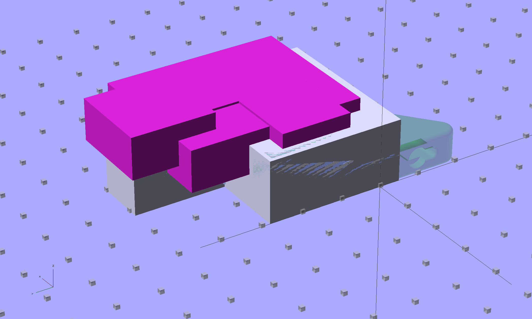
Because STL files aren’t editable, I reverse-engineered the dimensions into an OpenSCAD model that I could use as the basis for a different guide. This is just the basic wire cover, minus the filament guide extension, plus a flat end that wraps around the edge of the chassis:
M2 Wire Cover – reverse engineered
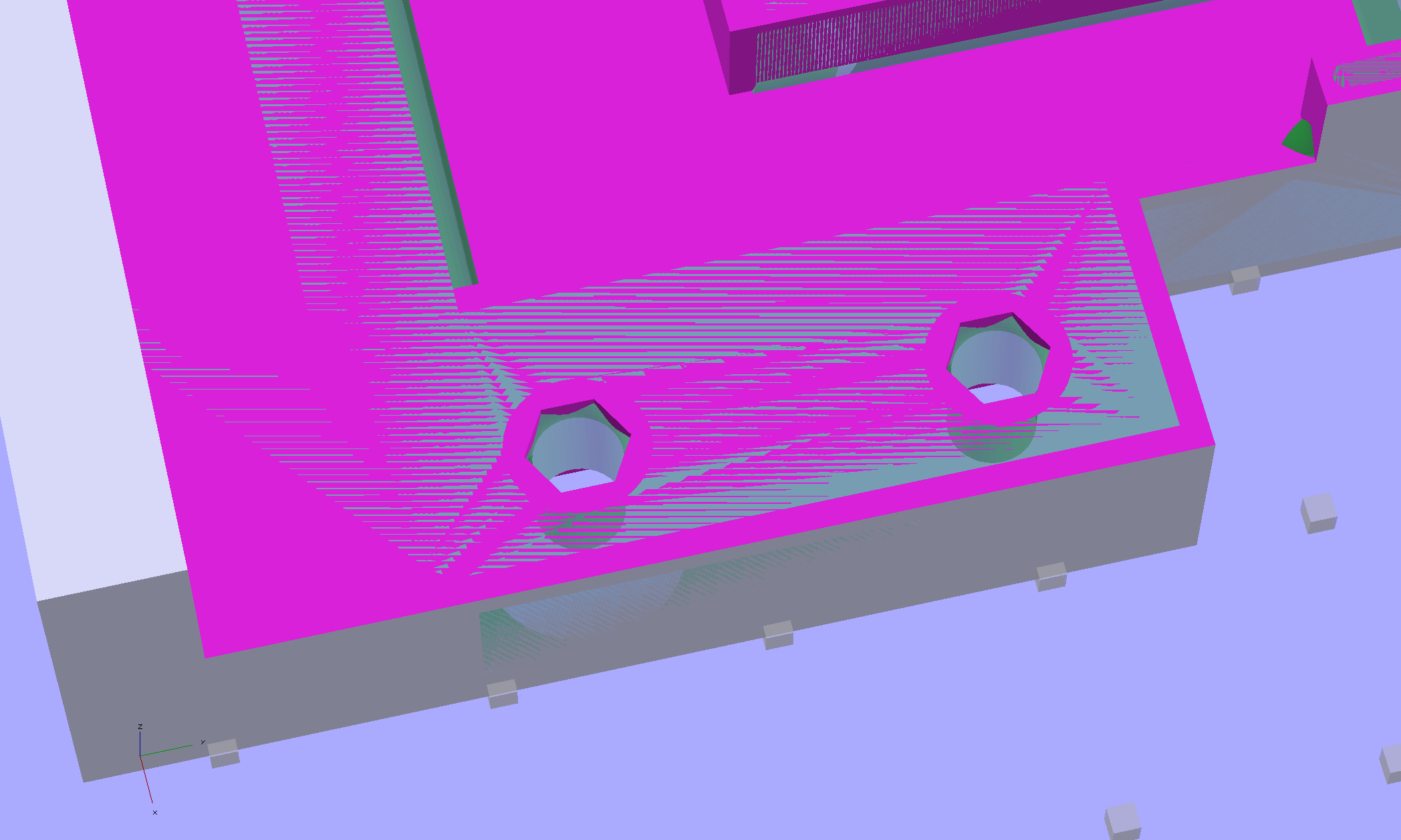
The trick is to import the STL into OpenSCAD, then build a model that matches the key dimensions. Fortunately, Makergear used hard metric sizes for everything, so most of the numbers came out as integers or single-place decimals:
The shimmer indicates coincident surfaces; that’s ordinarily a Very Bad Thing, but in this case it shows that the dimensions match. The top of the holes have neat hexagonal patterns where my straight-sided PolyHoles extend through their chamfered circular holes:
Unlike my from-scratch OpenSCAD models, this one bristles with magic numbers that describe the dimensions of the M2 STL model. The basic shape comes from an extruded polygon matching the outside walls, another extruded polygon knocking out the wire channel, then cubes lopping off the top surfaces:
M2 Wire Cover Filament Guide – overlay – F12 view
The end result of all that thrashing around has a certain Soviet Concrete look to it:
M2 Wire Cover – OpenSCAD solid model
This version lacks the filament guide; I wanted to make sure all the protrusions and channels fit, which they sort of did:
M2 reverse engineered wire cover – installed
The next version will have slightly more clearance on the side and slightly less on the top; that’s easy to do now that I have an editable OpenSCAD model.
The OpenSCAD source code:
// Improved M2 filament guide and X-min switch wire guide
// Ed Nisley KE4ZNU - Oct 2013

function IntegerMultiple(Size,Unit) = Unit * ceil(Size / Unit);

Protrusion = 0.1;

HoleWindage = 0.2;

//- Sizes

PlateMinThick = 8.0;				// basic thickness excluding wire guides
PlateLength = 5.0;					// from side of frame beyond top wire guide

TopGuideLength = 7.0;				// protrusion from plate

PlateThick = PlateMinThick + TopGuideLength;

echo(str("Total thickness: ",PlateThick));

//- Adjust hole diameter to make the size come out right

module PolyCyl(Dia,Height,ForceSides=0) {			// based on nophead's polyholes

  Sides = (ForceSides != 0) ? ForceSides : (ceil(Dia) + 2);

  FixDia = Dia / cos(180/Sides);

  cylinder(r=(FixDia + HoleWindage)/2,h=Height,$fn=Sides);
}

//- Put peg grid on build surface

module ShowPegGrid(Space = 10.0,Size = 1.0) {

  RangeX = floor(100 / Space);
  RangeY = floor(125 / Space);

	for (x=[-RangeX:RangeX])
	  for (y=[-RangeY:RangeY])
		translate([x*Space,y*Space,Size/2])
		  %cube(Size,center=true);

}

//- Define basic block shape
//  Mostly reverse engineered from
//    https://github.com/MakerGear/M2/blob/master/Printed%20Parts/STL/M2%20X%20Endstop%20Wire%20Cover%20with%20Filament%20Guide.stl
//	Hence all the magic numbers...

module BaseBlock() {

SideGuideLength = 4.0;				// protrusion = even with frame interior
ChannelDepth = 4.5;					// wiring channel
FrameOffset = 28;

	translate([18,FrameOffset,0]) {			// align neatly for later processing

		if (true)
			color("Green",0.3)
				translate([-18,22,15])
					rotate([-90,0,-90])
						import("/mnt/bulkdata/Project Files/Thing-O-Matic/M2 Parts/Filament Guide/M2+X+Endstop+Wire+Cover+with+Filament+Guide.stl",
								convexity=10);

		difference() {
			linear_extrude(height=PlateThick,convexity=5)		// main block
				polygon(points=[[0,0],[0,22],[12,22],[12,7.5],[22,7.5],
								[22,-(PlateLength + FrameOffset)],[-18,-(PlateLength + FrameOffset)],
								[-18,0]
						]);

			for (i=[-1,0])
				translate([17,((i*15.0)+ 1.05),-Protrusion])
					rotate(180/6) {
						PolyCyl(3.1,(PlateMinThick + 2*Protrusion),6);		// screw holes
						PolyCyl(5.7,(3.0 + Protrusion),6);					//  ... countersink
					}

			translate([0,0,(PlateMinThick - ChannelDepth)])		// wire channel
				linear_extrude(height=15,convexity=5)
					polygon(points=[[2,-5],[2,19],[10,19],[10,-22],[-15,-22],[-15,-5]
							]);

			translate([-10,14,PlateMinThick])				// M2 frame
				rotate(-90)
					cube([42,35,10],center=false);

			translate([-5,5,(PlateMinThick + SideGuideLength)])	// shorten side guide
				cube([20,20,10],center="false");

		}
	}

}

//- Build it

ShowPegGrid();

BaseBlock();
My desktop box (an off-lease Dell Optiplex 780) work up dead a while back, but recovered; I figured an insurance policy might be a good idea, so a new-to-me off-lease Dell Optiplex 980 just arrived. It booted into Windows Vista Business, whereupon:
Apply all the usual Windows updates
Boot SysRescCD from USB, run GPartEd
Shrink the Windows partition (/dev/sda1) to 25 GB
Slide the recovery partition (/dev/sda2) over against it
Create 10 GB swap partition (/dev/sda3), likely never to be used with 4 GB of RAM
Create extended partition (/dev/sda4)
Create 35 GB Linux partition (/dev/sda5)
Then install Xubuntu 13.10 using the mini ISO USB, put GRUB in the MBR, reboot, and … get Vista again. Huh. This is not a nominal outcome.
For whatever reason, GRUB either doesn’t get control or defaults to the Windows partition. However, attempting to boot from the mini ISO transfers control to GRUB, thence to Xubuntu, and attempting to boot from SysRescCD works fine. Boot to Xubuntu, tinker with /etc/default/grub, run update-grub, and it still doesn’t work. Well, it boots Vista, but that doesn’t work for me; no error messages, either.
The box runs BIOS A07, so:
Fetch BIOS A14
Boot Windows, update the BIOS
Check the settings and discover that the hard drive is set to RAID mode
Change that to RAID Autodetect – AHCI
Ignore warnings about possible reinstall; box doesn’t come with a reinstall CD
Reboot and it’s all good: GRUB is now in full control
Both Vista and Xubuntu work fine
I think the problem came from having a single hard drive set to RAID mode. Dunno what they had in mind with that; it’s a small form factor box with no room for another drive…
Memo to Self: Yet Another Thing To Preemptively Un-Wedge