Ed Nisley's Blog: Shop notes, electronics, firmware, machinery, 3D printing, laser cuttery, and curiosities. Contents: 100% human thinking, 0% AI slop.
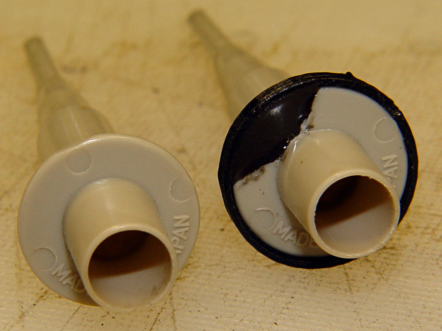
Quite some time ago I manage to break the finger flange on one of my scope probes and, what with it being made of an un-glueable engineering plastic, a simple repair job failed quickly. It’s entirely round and a perfect lathe project, but … this is easier:
HP Scope Probe Flange Repair
You can see remnants of that failed repair just below the fracture:
HP scope probe flanges – repair disk
Some epoxy around the rim of the flange, plus filling the missing sector, looks about as grubby as you’d expect:
HP Scope Probes – rear
That’s a tiny zit at about 1 o’clock which came off with fingernail pressure.
From the business end, it actually looks pretty snappy:
HP Scope Probes – front
I’m mildly tempted to preemptively reinforce the other probes…
The OpenSCAD source code joins two parts with coincident faces, but it worked out OK for once:
// Tek Scope Probe Flange
// Ed Nisley KE4ZNU November 2013

//- Extrusion parameters must match reality!
//  Print with 2 shells and 3 solid layers

ThreadThick = 0.25;
ThreadWidth = 0.40;

HoleWindage = 0.2;

Protrusion = 0.1;			// make holes end cleanly

function IntegerMultiple(Size,Unit) = Unit * ceil(Size / Unit);

//----------------------
// Dimensions

FlangeOD = 16.0;
FlangeID = 8.75;
FlangeThick = IntegerMultiple(1.25,ThreadThick);

DiskOD = FlangeOD + 4*ThreadWidth;
DiskThick = FlangeThick + 4*ThreadThick;

NumSides = 8*4;

//----------------------
// Useful routines

module PolyCyl(Dia,Height,ForceSides=0) {			// based on nophead's polyholes

  Sides = (ForceSides != 0) ? ForceSides : (ceil(Dia) + 2);

  FixDia = Dia / cos(180/Sides);

  cylinder(r=(FixDia + HoleWindage)/2,
           h=Height,
	   $fn=Sides);
}

module ShowPegGrid(Space = 10.0,Size = 1.0) {

  Range = floor(50 / Space);

	for (x=[-Range:Range])
	  for (y=[-Range:Range])
		translate([x*Space,y*Space,Size/2])
		  %cube(Size,center=true);

}

//----------------------
// Build it

ShowPegGrid();

	difference() {
		union() {
			translate([0,0,2*ThreadThick])
				cylinder(r=DiskOD/2,h=DiskThick,$fn=NumSides);			// main repair part
			cylinder(r1=(DiskOD - 2*ThreadWidth)/2,r2=DiskOD/2,h=2*ThreadThick,$fn=NumSides);
		}
		translate([0,0,(DiskThick - FlangeThick)])				// flange clearance
			PolyCyl(FlangeOD,2*FlangeThick,NumSides);
		translate([0,0,-DiskThick/2])
			PolyCyl(FlangeID,2*DiskThick,NumSides);
	}
I’ve been working on an object (more on this later) that requires precise alignment of two parts that capture a nut deep inside. This calls for alignment pins, similar to the ones I used for, say, the Triple-Cylinder Thing:
Cylinder Thing – rotated
The general idea is to design holes that fit the pins, then locate them at the parting line of the model, where they’re subtracted from the solid and appear in exactly the proper places when the model splits for printing:
Cylinder Thing – alignment pegs
You slather solvent glue on both halves, jam pins into the holes, slap the parts together, and clamp until cured. Works fine, I use pins all over the place.
The gotcha of using just a (polygonal) cylinder as the hole: if you glue one end of the pin at a time, a small rim of dissolved plastic may form around the pin at the surface. That can bond the two halves together or prevent them from joining properly after being disassembled.
Sooo, here’s a new alignment pin hole with a gutter around the pin on both surfaces to capture the glop:
Alignment pin hole – overview
Remember, that’s the negative volume that will hold the pin, not the pin itself!
Here’s how it works in real plastic, with a 1.75 mm peg glued into one hole with a bit of crud in the gutter:
Alignment Hole and Pin
The secret to making the gutter work: offset the second layer by half the thread width, so that it’s reasonably well supported on the first layer. If you don’t do that, the inner layers simply drop down through the hole and fill the gutter. Even doing that, notice the distortion of the first few layers inside the hole.
The OpenSCAD source code looks about like you’d expect:
Ideally, the pin length should extend at least two diameters into each side of the object, but you can feed in whatever you need to make it come out right.
The PolyCyl() routine produces a low-vertex-count polygon that circumscribes the nominal diameter, which is what you need for vertical holes in 3D printed objects:
module PolyCyl(Dia,Height,ForceSides=0) {			// based on nophead's polyholes

  Sides = (ForceSides != 0) ? ForceSides : (ceil(Dia) + 2);

  FixDia = Dia / cos(180/Sides);

  cylinder(r=(FixDia + HoleWindage)/2,
           h=Height,
	   $fn=Sides);
}
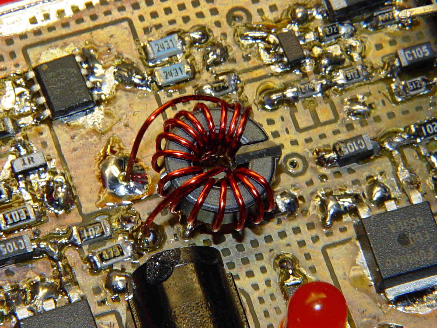
Although it’s not obvious, the two blue 2431 Ω resistors just above the toroid are a divider that scales the switched battery voltage (from the p-MOSFET on their left) by 50% and sends it to input A0 on the Arduino Pro Mini board:
Figuring the actual battery voltage is straightforward:
get 10 bit ADC value with analogRead()
multiply by actual VCC (measured at 4.96 V for this board)
divide by actual voltage divider ratio (measured at 3.78/7.57)
Which, of course, reported the battery voltage was 4.116 V. Huh?
After spending far too much time poking the code with a sharp stick, I wired the divider to the (previously unused) A6 and A7 inputs and dumped the raw ADC counts for all three. The answer should be somewhere near 763, but the three values came out around 215, 667, and 750. Huh?
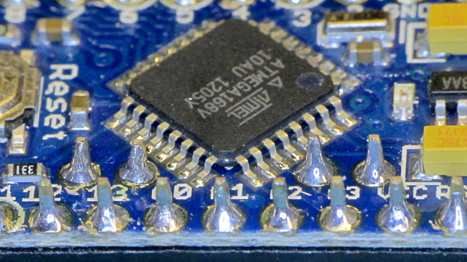
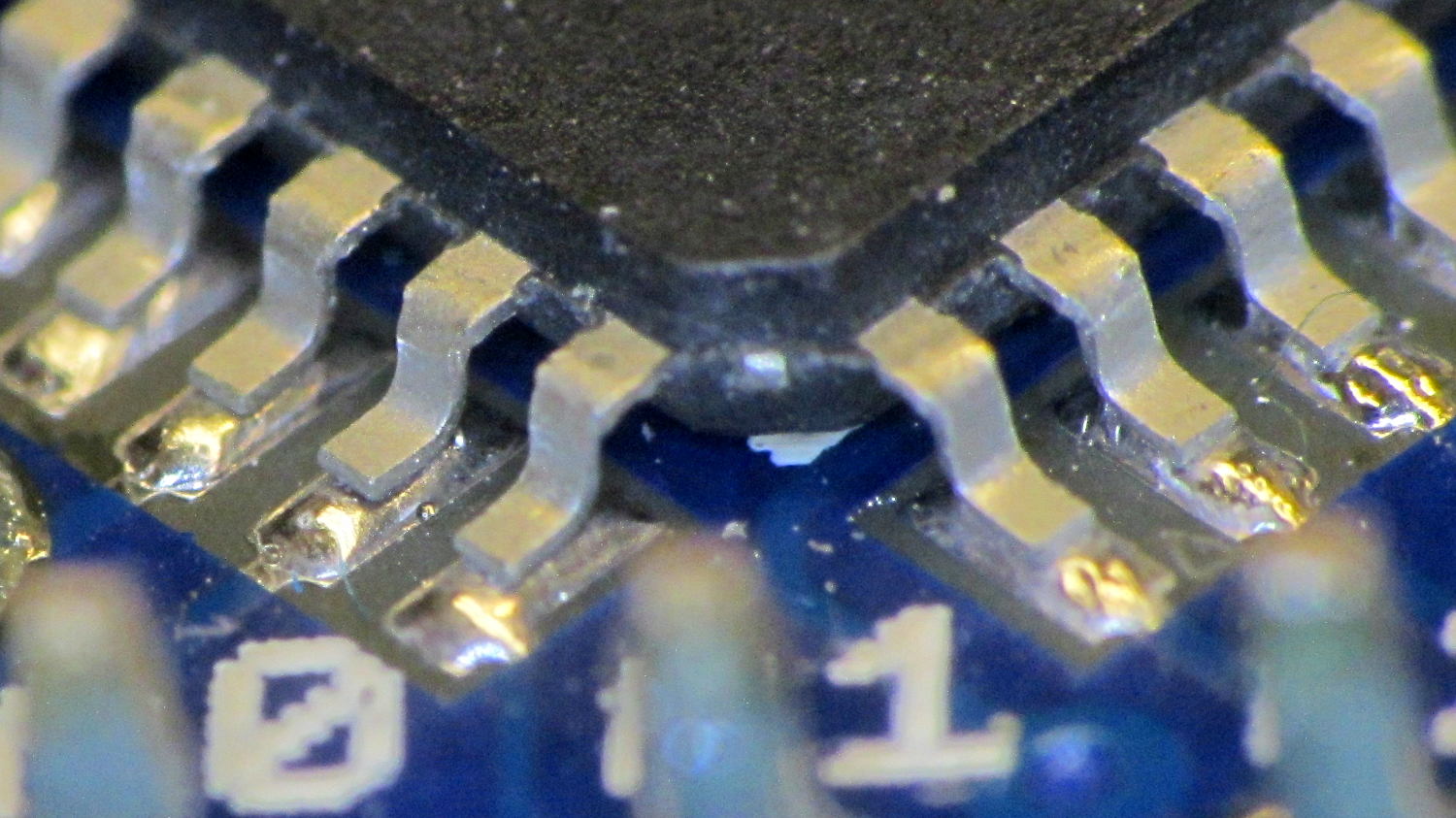
The A0 value is totally bogus, so I finally looked at the Arduino Pro Mini board:
Arduino Pro Mini clone – chip overview
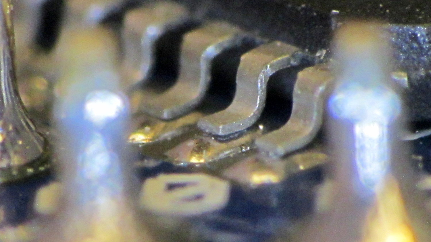
Hmmm. It turns out A0 is the second pin back on the left side:
I slathered flux on all the pins, touched each one with a soldering iron, and it’s all good.
This is a knockoff Arduino Pro Mini board from eBay, of course, and the rest of the boards in that lot were OK. Their QC inspection almost certainly boils down to running the Blink sketch: if the LED blinks after the power goes on, ship it!
Blink doesn’t verify the analog inputs, which turn out to be wrapped around that corner of the package.
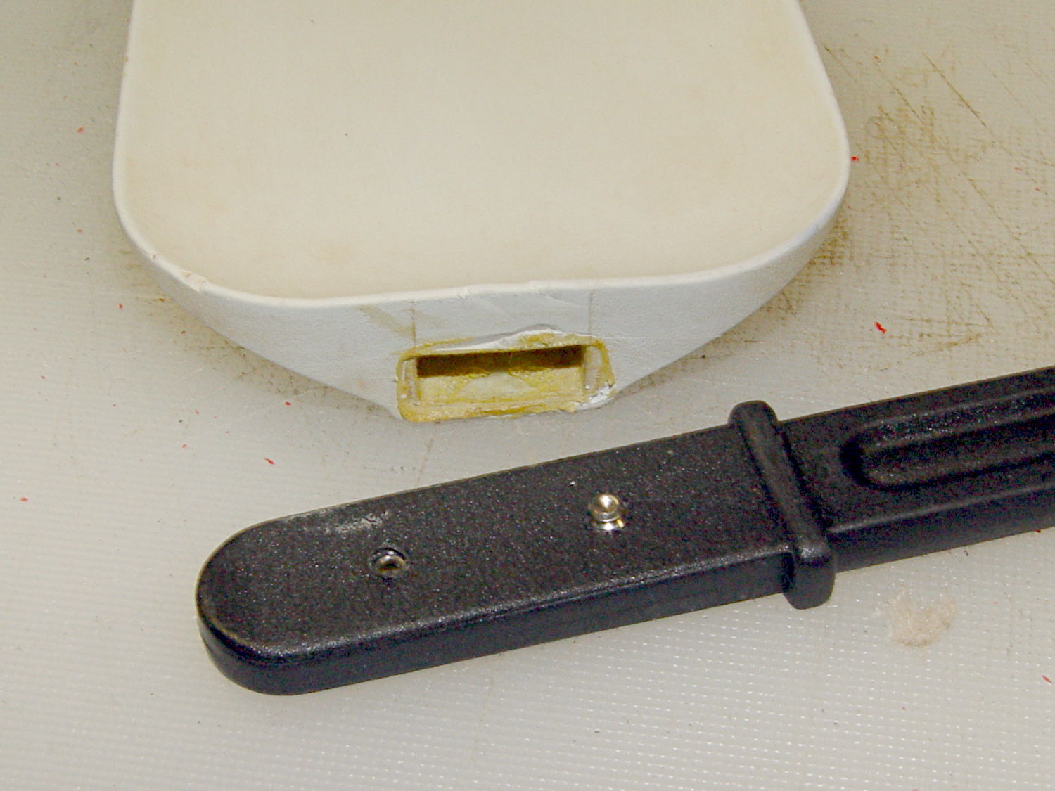
Shortly after we bought this kitchen scraper spatula (or whatever it’s called), the handle pulled out of the blade and left it sitting in a bowl of batter. That turned out to be unsurprising, given that neither side of the interface has any mechanical locking features. I rinsed the batter off, stuck some urethane glue inside, rammed the handle in place, and hoped for the best. Lacking any mechanical interlock and not bonding to either surface, the adhesive didn’t improve the situation.
So I recently added a pair of stainless 4-40 setscrews standing just proud of the handle’s surface that should dig into the blade and hold it in place:
After rebuilding the front end of the Samsung vacuum’s floor brush, I’d hoped that was the end of it; other than replacing the brush strips every now and again, it’s been cooperative. Recently, however, one of the wheels popped off, which revealed the minimal mechanism holding them in place:
Samsung Quiet Jet – floor brush wheel interior
Those four delicate latches have worn themselves and the hub to the point where they ride over the edge at the slightest provocation. I pulled both wheels off and packed three turns of insulated wire (one turn is visible in the photo, as it was an iterative process) around the outside of the clips, with the intent of restoring enough force to hold the wheels in place until we exhaust the lifetime supply of bags I bought for the thing…
What’s the difference between the winding on this toroid:
Hall effect sensor – toroid CW field
And the winding on this one:
Hall effect sensor – toroid CCW field
Very good!
In the first picture, the top lead goes down the hole. In the second picture, the bottom lead goes down the hole.
Bonus question 1: Why is this important?
The winding’s chirality determines the direction of the magnetic field in the toroid by the right hand rule: grab the wire with your right hand, with your thumb pointed in the direction of (conventional) current flow, then your fingers wrap around the wire in the direction of the induced field.
The Hall effect sensor snuggled in the toroid’s gap produces a bipolar output that depends on both the magnetic field’s direction and intensity, so reversing the field direction changes the phase of the sensor output: an increasing field can either increase or decrease the sensor’s output.
Bonus question 2: For a given sensor orientation, what’s the probability of winding the toroid correctly on the first try?
It’s not practical to reverse the sensor orientation, the leads weren’t quite long enough to swap, and turning the toroid upside-down is effectively the same as swapping the too-short leads.
The size of the solder blob at the end of the top lead tells you everything you need to know about the sequence of the picvtures.
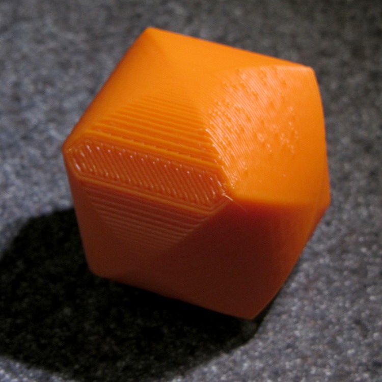
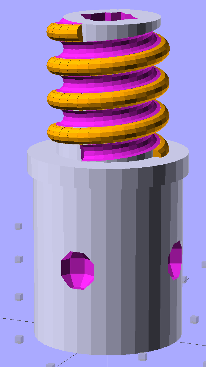
Although the current OpenSCAD could produce a solid model with the screw thread’s dedendum, I’d never actually printed one of them:
Broom Handle Screw – full thread – solid model
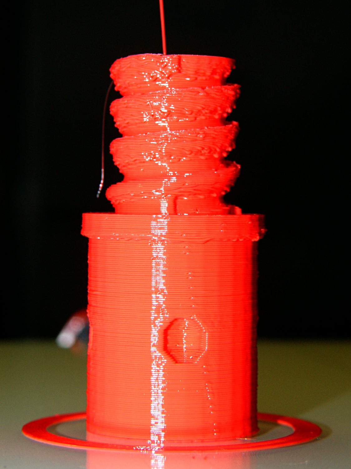
I need some fondlestuff illustrating how to handle overhangs, so I ran one standing vertically, which (pretty much as I expected) didn’t work well at all:
Broom Handle Screw – dedendum – vertical
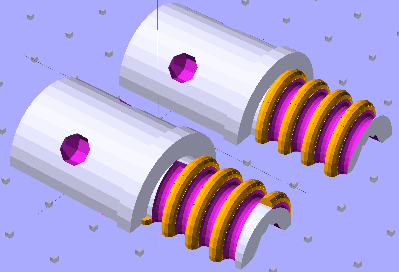
The trick is to split the model down the middle:
Broom Handle Screw – horizontal top
And put holes in each half for alignment pins:
Broom Handle Screw – horizontal bottom
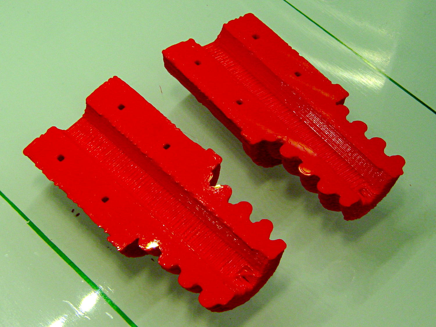
Then you can print it lying down:
Broom Handle Screw – horizontal – as-printed top
The internal overhang would probably call for some support material, particularly in the square recess at the end, but in this case it’s a lesson:
Glue some filament snippets into the holes, snap it together, and it looks just fine over there on the right:
Broom Handle Screw – orientation comparison
Doesn’t matter how many I print, it still doesn’t make any economic sense as a broom repair…
The OpenSCAD source code now has a Layout variable to control the orientation and, not as shown in the model, the alignment pins have glue gutters in the first layer:
// Broom Handle Screw End Plug
// Ed Nisley KE4ZNU October 2013

Layout = "Horizontal";		// Vertical Horizontal Pin

UseDedendum = true;			// true to create full thread form

//- Extrusion parameters must match reality!

ThreadThick = 0.25;
ThreadWidth = 0.40;

HoleWindage = 0.2;

Protrusion = 0.1;			// make holes end cleanly

//----------------------
// Dimensions

PostOD = 22.3;				// post inside metal handle
PostLength = 25.0;

FlangeOD = 24.0;			// stop flange
FlangeLength = 3.0;

PitchDia = 15.5;			// thread center diameter
ScrewLength = 20.0;

ThreadFormOD = 2.5;			// diameter of thread form
ThreadPitch = 5.0;
NumSegments = 32;			//  .. number of cylinder approximations per turn

BoltOD = 7.0;				// clears 1/4-20 bolt
BoltSquare = 6.5;			// across flats
BoltHeadThick = 3.0;

RecessDia = 6.0;			// recesss to secure post in handle

OALength = PostLength + FlangeLength + ScrewLength;

SplitOC = 1.25*FlangeOD;	// separation in Horizontal layout
PinOD = 1.75;				// alignment pin diameter = filament stub
PinLength = 7.0;			//  ... length

$fn=8*4;					// default cylinder sides

echo("Pitch dia: ",PitchDia);
echo("Root dia: ",PitchDia - ThreadFormOD);
echo("Crest dia: ",PitchDia + ThreadFormOD);

Pi = 3.14159265358979;

//----------------------
// Useful routines

// Wrap cylindrical thread segments around larger plug cylinder

module CylinderThread(Pitch,Length,PitchDia,ThreadOD,PerTurn) {

CylFudge = 1.02;				// force overlap

    RotIncr = 1/PerTurn;
    PitchRad = PitchDia/2;

    Turns = Length/Pitch;
    NumCyls = Turns*PerTurn;

    ZStep = Pitch / PerTurn;

    HelixAngle = atan(Pitch/(Pi*PitchDia));
    CylLength = CylFudge * (Pi*(PitchDia + ThreadOD) / PerTurn) / cos(HelixAngle);

	for (i = [0:NumCyls-1]) {
		assign(Angle = 360*i/PerTurn)
			translate([PitchRad*cos(Angle),PitchRad*sin(Angle),i*ZStep])
				rotate([90+HelixAngle,0,Angle])
					cylinder(r1=ThreadOD/2,
							r2=ThreadOD/(2*CylFudge),
							h=CylLength,
							center=true,$fn=12);
	}
}

// Build complete plug

module ScrewPlug() {
	difference() {
		union() {
			cylinder(r=PostOD/2,h=PostLength);
			cylinder(r=PitchDia/2,h=OALength);
			translate([0,0,PostLength])
				cylinder(r=FlangeOD/2,h=FlangeLength);
			color("Orange")
			translate([0,0,(PostLength + FlangeLength)])
				CylinderThread(ThreadPitch,(ScrewLength - ThreadFormOD/2),PitchDia,ThreadFormOD,NumSegments);
		}

		translate([0,0,-Protrusion])
			PolyCyl(BoltOD,(OALength + 2*Protrusion),6);

		translate([0,0,(OALength - BoltHeadThick)])
			PolyCyl(BoltSquare,(BoltHeadThick + Protrusion),4);

		if (UseDedendum)
			translate([0,0,(PostLength + FlangeLength + ThreadFormOD/2 - ThreadPitch/(2*NumSegments))])
				rotate(-90 - 360/(2*NumSegments))
				CylinderThread(ThreadPitch,ScrewLength,PitchDia,ThreadFormOD,NumSegments);

		for (i = [0:90:270]) {
			rotate(45 + i)					// 45 works better with Horizontal layout
				translate([PostOD/2,0,PostLength/2])
					sphere(r=RecessDia/2,$fn=8);
		}
	}
}

// Locating pin hole with glue recess

module LocatingPin() {

	translate([0,0,-ThreadThick])
		PolyCyl((PinOD + 2*ThreadWidth),2*ThreadThick,4);
	translate([0,0,-(PinLength/2 + ThreadThick)])
		PolyCyl(PinOD,(PinLength + 2*ThreadThick),4);

}

module PolyCyl(Dia,Height,ForceSides=0) {			// based on nophead's polyholes

  Sides = (ForceSides != 0) ? ForceSides : (ceil(Dia) + 2);

  FixDia = Dia / cos(180/Sides);

  cylinder(r=(FixDia + HoleWindage)/2,
           h=Height,
	   $fn=Sides);
}

module ShowPegGrid(Space = 10.0,Size = 1.0) {

  Range = floor(50 / Space);

	for (x=[-Range:Range])
	  for (y=[-Range:Range])
		translate([x*Space,y*Space,Size/2])
		  %cube(Size,center=true);

}

//-------------------
// Build it...

ShowPegGrid();

if (Layout == "Vertical")
	ScrewPlug();

if (Layout == "Pin")
	LocatingPin();

if (Layout == "Horizontal")
	for (i=[-1,1])
		difference() {
			translate([i*SplitOC/2,PostLength/2,0])
				rotate([90,180*(i + 1)/2,0])
					ScrewPlug();

			translate([0,0,-FlangeOD/2])
				cube([2*OALength,2*OALength,FlangeOD],center=true);

			for (j=[-1,1], pin=[-1,1])
				assign(PinX = i*SplitOC/2 + pin*(PostOD + BoltOD)/4,
					   PinY = j*PostLength/4) {
					translate([PinX,PinY,0])
						rotate(45)
							LocatingPin();
					echo("i j pin: ",i,j,pin);
					echo("X Y: ",PinX,PinY);
				}
		}