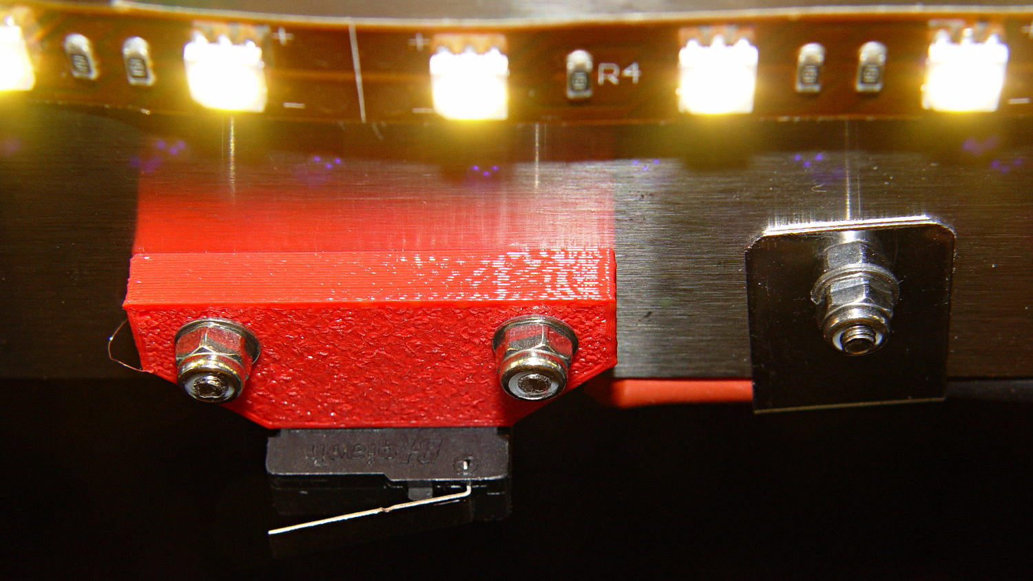
The houseplants have migrated indoors after spending a summer charging up in the sun on the patio, which means it’s time to replace the silicone rubber feet on the bottom of the plant shelves. This year, I printed a set of feet to fit the hex-head adjustable feet:
The pencil-stem plant on the left, for whatever it’s worth, is a perfectly healthy Rhipsalis that greatly enjoyed the summer sun.
The feet print upside-down to give the surface around the hex a smooth finish. I used Slic3r’s Hilbert Curve for pattern a bit more interesting than the usual parallel lines:

The Hilbert curve doesn’t fit neatly into a non-rectangular shape, but it’s close enough.
The solid model includes the support structure:

Which pops out cleanly:

Yes, that’s a shred of red filament embedded on the left side. Cleanliness is next to impossible…
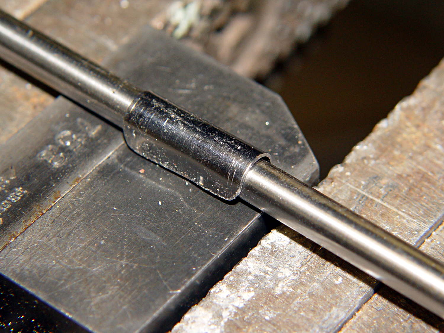
The fuzzy felt feet come from a 6 mm thick slab of the stuff:

The round socket wall leaves about 2 mm of felt showing at the bottom; it’s not very compressible and that should suffice to keep the plastic off the table.
The OpenSCAD source code:
// Feet for a wire-shelf plant stand
// Ed Nisley KE4ZNU October 2013

Layout = "Build";			// Show Build

Support = true;

//- Extrusion parameters must match reality!
//  Print with 2 shells and 3 solid layers

ThreadThick = 0.25;
ThreadWidth = 0.40;

HoleWindage = 0.2;

Protrusion = 0.1;			// make holes end cleanly

//----------------------
// Dimensions

StandFootOD = 18.0;			// hex across flats
StandFootDepth = 5.0;		//  ... socket depth

FeltPadOD = 25.0;			// felt foot diameter
FeltPadDepth = 4.0;			//  ... depth

FootBaseThick = 6*ThreadThick;	// between foot and pad
FootWall = 4*ThreadWidth;		// around exterior

FootOD = 2*FootWall + max(StandFootOD,FeltPadOD);
echo(str("Foot OD: ",FootOD));

FootTall = StandFootDepth + FootBaseThick + FeltPadDepth;
echo(str(" ... height: "),FootTall);

NumSides = 8*4;

//----------------------
// Useful routines

module FootPad() {

	difference() {

		cylinder(r=FootOD/2,h=FootTall,$fn=NumSides);

		translate([0,0,FeltPadDepth + FootBaseThick])
			PolyCyl(StandFootOD,2*StandFootDepth,6);

		translate([0,0,-Protrusion])
			PolyCyl(FeltPadOD,(FeltPadDepth + Protrusion),NumSides);

	}
}

// Locating pin hole with glue recess

module LocatingPin() {

	translate([0,0,-ThreadThick])
		PolyCyl((PinOD + 2*ThreadWidth),2*ThreadThick,4);
	translate([0,0,-(PinLength/2 + ThreadThick)])
		PolyCyl(PinOD,(PinLength + 2*ThreadThick),4);

}

module PolyCyl(Dia,Height,ForceSides=0) {			// based on nophead's polyholes

  Sides = (ForceSides != 0) ? ForceSides : (ceil(Dia) + 2);

  FixDia = Dia / cos(180/Sides);

  cylinder(r=(FixDia + HoleWindage)/2,
           h=Height,
	   $fn=Sides);
}

module ShowPegGrid(Space = 10.0,Size = 1.0) {

  Range = floor(50 / Space);

	for (x=[-Range:Range])
	  for (y=[-Range:Range])
		translate([x*Space,y*Space,Size/2])
		  %cube(Size,center=true);

}

//-------------------
// Build it...

ShowPegGrid();

if (Layout == "Show")
	FootPad();

if (Layout == "Build") {
	translate([0,0,FootTall])
		rotate([180,0,0])
			FootPad();
	if (Support)
		color("Yellow")
			for (Seg=[0:5]) {
				rotate(30 + 360*Seg/6)
				translate([0,0,(StandFootDepth - ThreadThick)/2])
					cube([(StandFootOD - 3*ThreadWidth),
						  2*ThreadWidth,
						  (StandFootDepth - ThreadThick)],
						  center=true);
				}
}