Ed Nisley's Blog: Shop notes, electronics, firmware, machinery, 3D printing, laser cuttery, and curiosities. Contents: 100% human thinking, 0% AI slop.
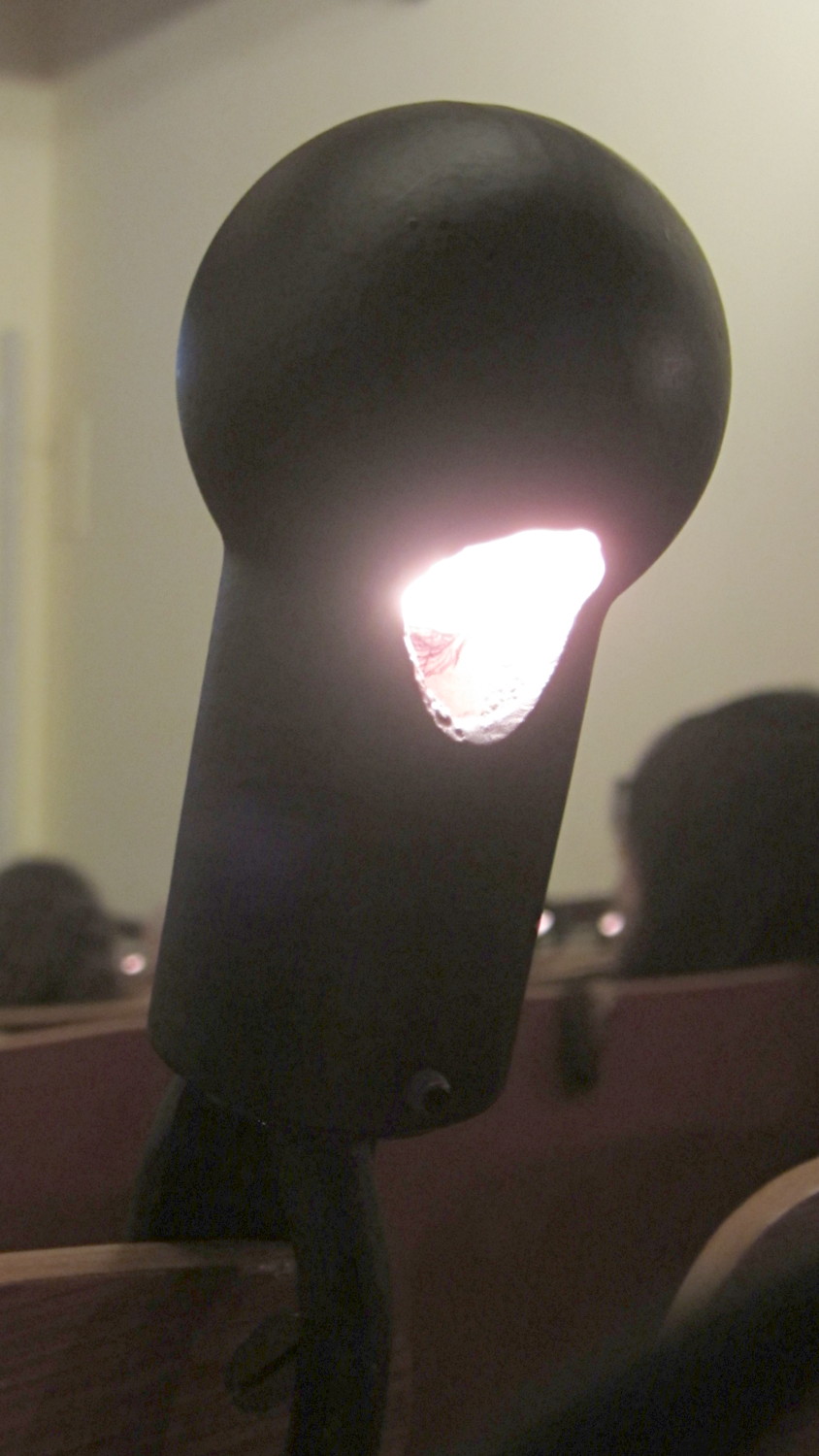
We attended a talk in the Taylor Hall Auditorium at Vassar College, which features lovingly restored lamps that illuminate the pull-up desks on each seat:
Vassar Taylor Hall – desk lamp
The housing consists of black-painted cast iron, with a 7 W (“Christmas tree”) incandescent bulb keeping it pleasantly warm to the touch. A metal conduit connects the lamp to the main conduit running parallel to the seat rows at the edge of each step. Another hole on the other side cast light upward toward the ceiling, perhaps providing general room light in the Good Old Days.
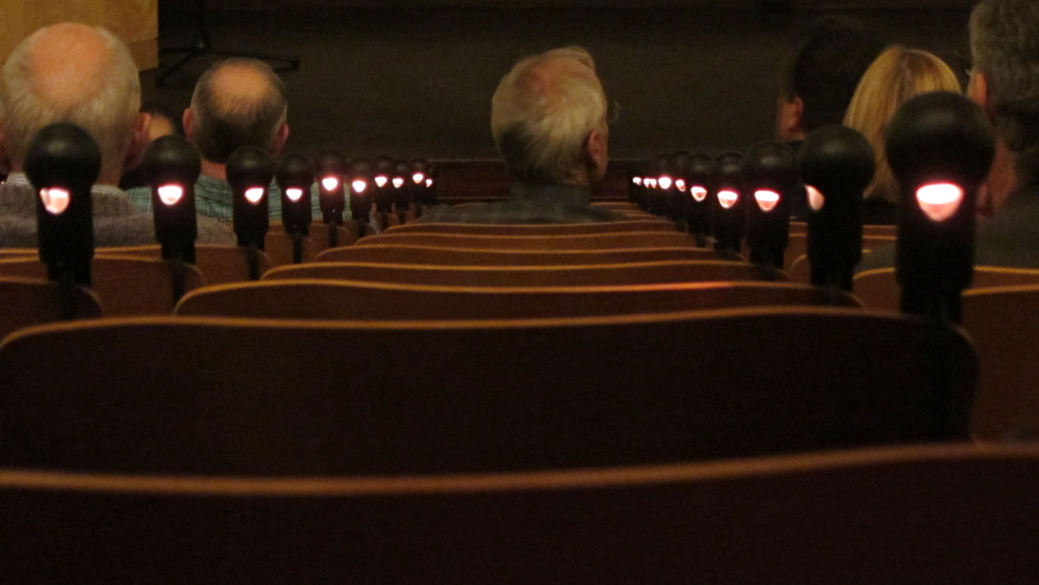
The restored seats are much wider than dictated by contemporary standards, perhaps allowing enough room for the classic conical skirts often seen in historic Vassar photographs:
Vassar Taylor Hall – desk lamp perspective
That’s about 170 W of light down those two rows. I didn’t think to run the numbers at the time, but there’s gotta be a kilowatt of those little lamps in that auditorium!
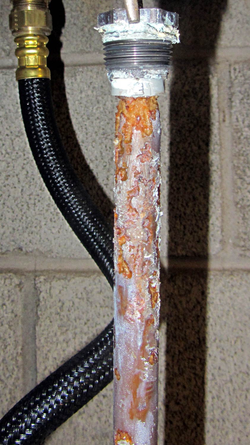
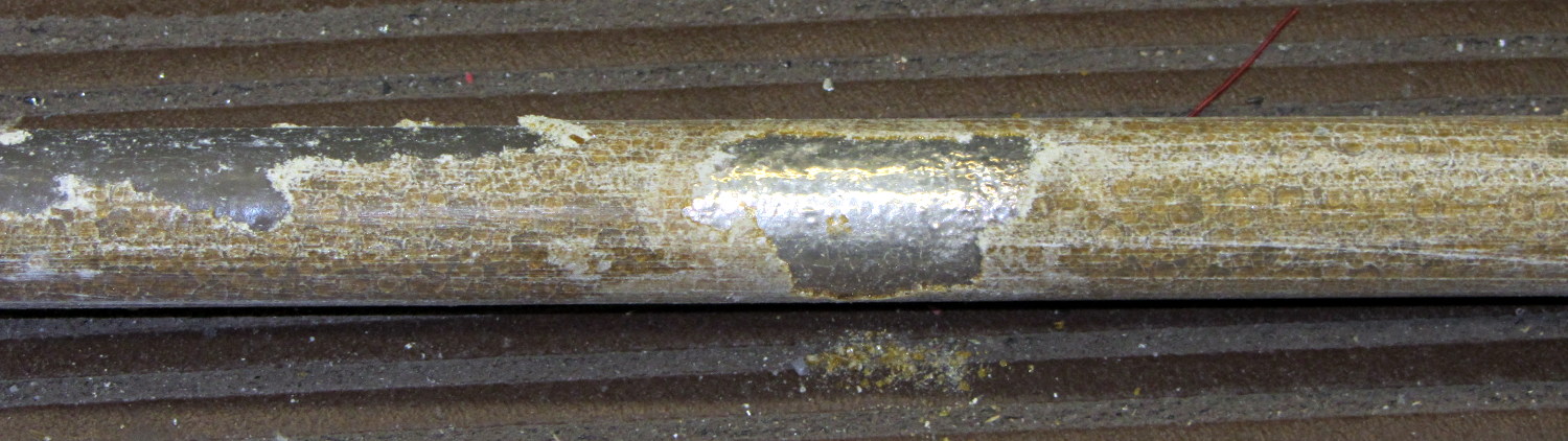
The Whirlpool water heater anode rod is corroding nicely:
Whirlpool anode rod – 2014-04
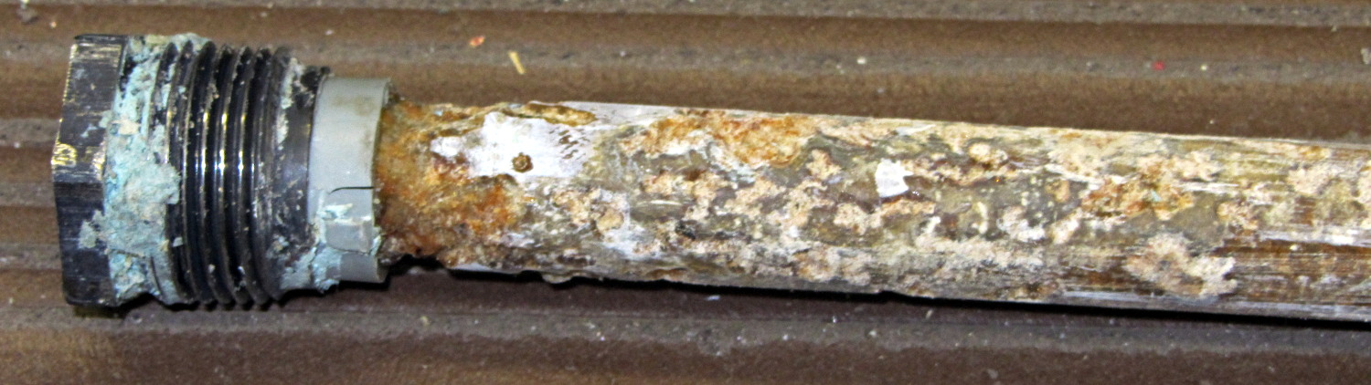
The new GE water heater anode rod seems to be passivating:
GE anode rod – coated – 2014-04
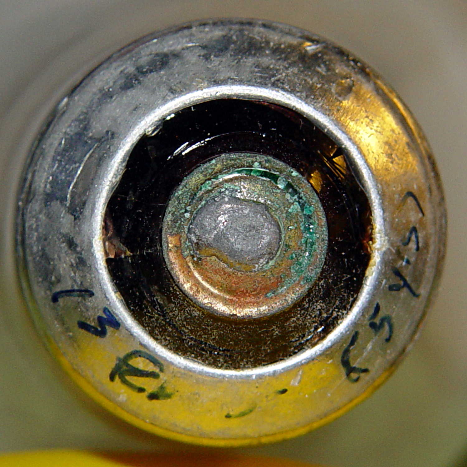
There’s some corrosion up near the bolt head, so it’s not entirely asleep:
GE anode rod – bolt – 2014-04
I hammered the coating off the rod, scuffed the shiny parts with coarse sandpaper, wiped off the dust, and stuck it back in its socket. We’ll see what it looks like next year.
Both tanks flushed nicely without too much sediment.
Two 40 W incandescent bulbs in the front bathroom burned out within a few days of each other. Being that type of guy, I know that I installed this bulb nine years ago:
Bulb base – install date
The date is easier to read with the bulb in hand: 13 Feb 05. The (5 yrs) indicates the previous bulb in that socket lasted five years.
The other bulb date went in during March 09, so it survived only five years; the previous bulb lasted 6 years.
Even though 40 W incandescent bulbs are history, maybe I have enough spares on the shelf that the next owner can replace ’em with cheap LEDs.
This may not be science, but it does have numbers…
After replacing the front wheel bearings, I replaced both pairs of brake pads. The rear brakes use holders with slide-in pads, but I’ve never been happy with the dinky little pins that retain the pads, so this time I’m using ordinary cotter pins:
V-brake pads – cotter pin retainer
The rear brake pads on a diamond-frame bike sit nearly horizontally on the seat stays, with the pin head pointed upward. On Tour Easy recumbents, the pads stand almost vertically on the chain stays, with the pins sideways:
Tour Easy rear brakes
That photo dates to 2010, when those brakes were new. Nary a pin has worked loose yet and I don’t expect they ever will, but …
If the pins rust before the pads wear out, I’ll go back to those little bitty OEM stainless pins.
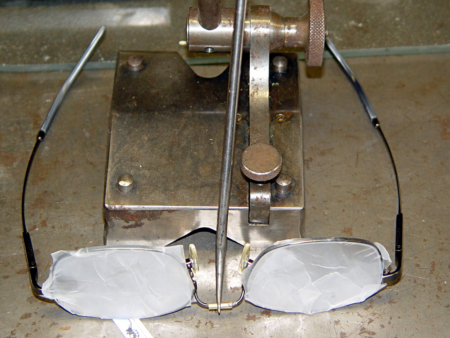
The nose bridge of my “computer glasses” snapped in the exact center, thus confirming my dislike of the springy head-clamping design. These never leave my desk, so I filled a small brass tube with epoxy, shimmed the lenses on a surface plate, tweaked the bridge into alignment with a surface gauge scribe, and let it cure overnight:
Crude nose bridge repair
That layout deliberately reduces the springiness by aligning the lenses to be parallel across the bridge, rather than being a bit side-eyed. They’re an un-bendable alloy that provides no way to tweak the alignment; they emerged just about perfect, but it’s time for a new pair later this year.
FWIW, they’re DIY “computer glasses”: +1 diopter to the far (“infinity”) correction and -1 diopter from the reading adder, producing a pair of glasses with the far point at about 1 meter and an unchanged reading-distance correction. That worked well, but next time I’ll use +0.75 diopter so I can sit back a bit further from those big monitors.
Also: the rust on that lovely surface gauge scribe base came from the previous owner and looks much worse in the picture than in real life. I should run it through an Evaporust bath the next time I have some out. It’s probably a Starrett Model 257, but with absolutely no maker marks whatsoever.
Having discovering that the chocolate mold positives suffered from sparse top infill, to the extent that silicone rubber would flow right though the surface…
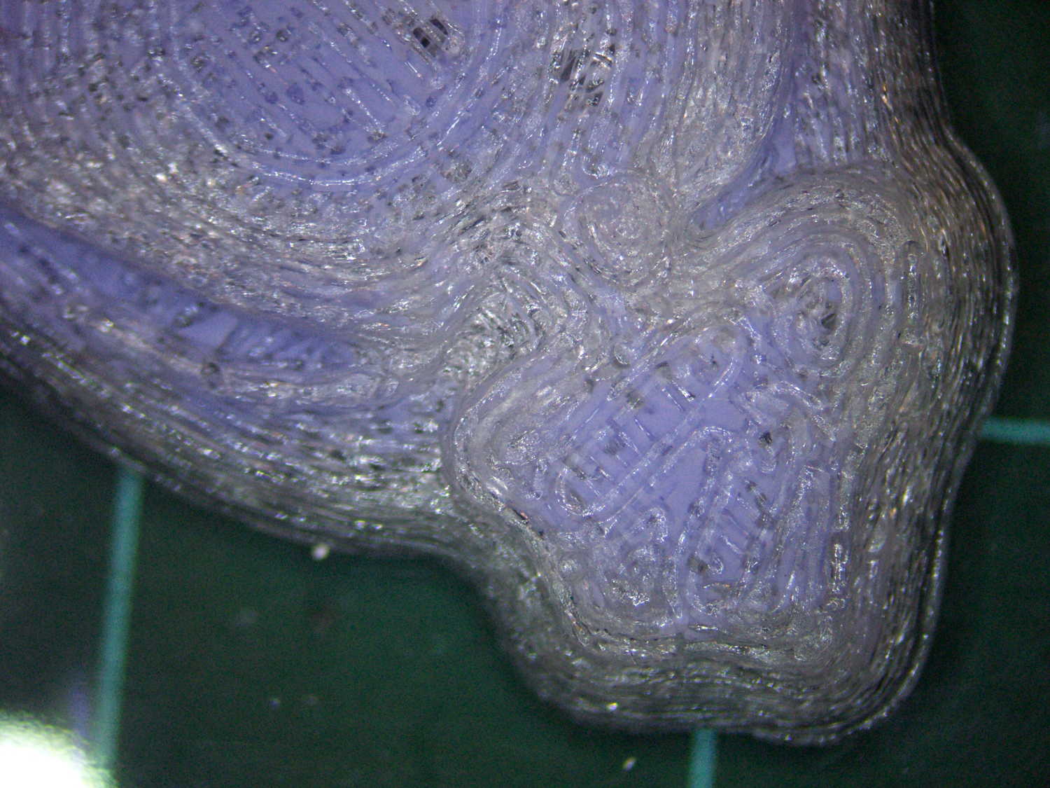
Not only were the infilled surfaces porous, I could see right through the block! That’s impossible to photograph, but here’s a laser beam shining through the entire 10 mm stack, showing how precisely the M2 aligns 50 under-filled thread layers:
Solid cube – laser transmission
The yellow spot in the middle marks the overexposed laser beam. There’s a distinct beam passing through the block that, with the proper orientation, can create a spot on the cutting mat atop my desk.
In fact, I can blow air through the blocks; one could use them as (rather coarse) air filters.
Normally, underfill happens when a mechanical problem prevents the printer from feeding enough filament to keep up with demand, but that’s not the case here: the perimeter threads came out exactly 0.4 mm wide for the entire height of the cube, as you can see if you click the picture for more dots. The top and bottom infill, plus all the interior threads, seem to be about half the nominal width and don’t touch their neighbors on the same XY plane at all.
The colors show the length of extruder filament per millimeter of XY motion, not the usual XY speed, with the two perimeter threads at 0.033 mm/mm and the interior at 0.18 mm/mm. In round numbers, the G-Code starves the infill by a factor of 1.8, which is close enough to the factor of two I’d guessed going into this mess.
Being that type of guy, I set the exact extrusion thickness and width (0.20 x 0.40 mm), rather than let Slic3r pick them. The extruded thread has a fixed cross-section of (roughly) 0.080 mm2 and a millimeter of XY motion thus requires 0.080 mm3 of filament.
The PLA filament measures 1.79 mm diameter, for a cross-section of 2.5 mm2. Getting 0.080 mm3 from the incoming filament requires feeding 0.032 mm into the extruder, which is almost exactly what you see for the perimeter threads.
After restoring Slic3r’s default configuration, the problem Went Away, which suggests that I backed the algorithms into a corner with some perverse combination of settings. Rebuilding my usual configuration from the defaults also worked fine, so it’s obviously not Slic3r’s problem.
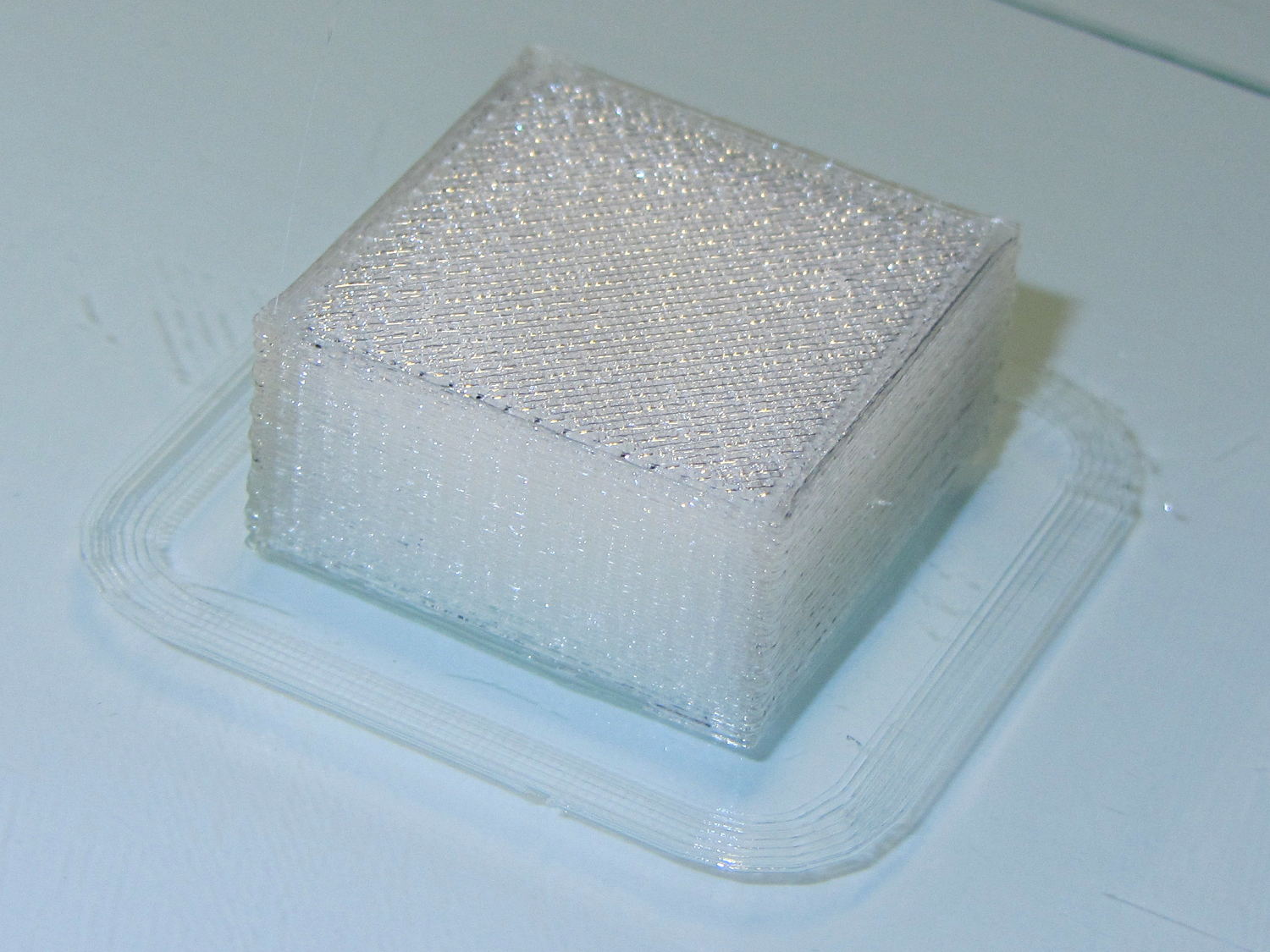
Which one is not like the other ones?
Solid cube tests
You can see the thin infill on three of those cubes, with the solid one in the lower right showing how it should look.
The solid cube weighs 4.4 g and the thin-fill variations weigh 2.7 to 2.9 g. Assuming PLA density = 1.25 g/cm3 and “cube” volume = 4 cm3, a completely solid cube should weigh 5.0 g. I think 4.4 g is close enough; the top surface came out flat with nice adjacent-thread fusion. Working backwards, the average fill = 88%; the perimeter is fused-glass solid, so the actual infill will be a bit under that.
I generally run Slic3r from my desktop box, with ~/.Slic3r symlinked to the actual config directory and its files on the NFS server downstairs. Perhaps running different versions of Slic3r on two or three different boxes, all using the same config files, wrecked something that didn’t show up in the UI and produced bad slices. I probably ran two different versions of Slic3r at the same time against the same files, although I wasn’t simultaneously typing at both keyboards.
Moral of the story: check the G-Code before assuming a hardware failure!