Ed Nisley's Blog: Shop notes, electronics, firmware, machinery, 3D printing, laser cuttery, and curiosities. Contents: 100% human thinking, 0% AI slop.
Depending on a solid model’s complexity, OpenSCAD will sometimes chew through system memory, consume the entire swap file, and then fall over dead. In an attempt to work around that situation, I recently jammed a 32 GB USB drive into the back of the box, turned it into a swap device, and then told the kernel to back off its enthusiasm for swapping.
Format the USB drive as a swap device:
sudo mkswap /dev/sd??   #--- unmount it before you do this!
Setting up swapspace version 1, size = 31265292 KiB
no label, UUID=0f559a8c-67b7-4fa3-a709-17aeec3104c4
Add it to /etc/fstab and set swap priorities:
# swap was on /dev/sdb3 during installation
UUID=e8532714-ad80-4aae-bee7-a9b37af63c8c none  swap sw,pri=1	0 0
UUID=0f559a8c-67b7-4fa3-a709-17aeec3104c4 none	swap sw,pri=5	0 0
Turn it on:
sudo swapon -a
Following those directions, dial back the kernel’s swappiness and limit the file cache growth:
For whatever reason, WordPress turns underscores into blanks, so those obvious typos aren’t, really.
And then it should Just Work.
The box has 4 GB of RAM and, under normal circumstances, doesn’t swap at all, so I expect the USB drive should kick in only for extreme OpenSCAD models. The swappiness tuning should help during ordinary operation with large file operations.
I have no results to report, but if something blows up, I know what changed…
Because the current control loop closes through the Arduino loop(), the code’s path length limits the bandwidth. Worse, the PWM filter imposes a delay while the DC value catches up with the new duty cycle. Here’s what that looks like:
LoopStatus ILED 50 mA div – 200 50 150 25 mA
The setpoint current for this pulse is 200 mA, ramping upward from 50 mA. It should have started from 25 mA, but the loop really wasn’t under control here.
The top trace goes low during the drain current measurement, which occurs just before the code nudges the gate drive by 1 PWM count to reduce the error between the setpoint and the measurement. A delay(1) after each PWM change, plus the inherent delay due to all the program statements, produces an update every 1.7 ms, more or less.
Even at that low rate, the current overshoots by 50 mA before the loop can tamp it down again. The current varies by 200 mA for 7 PWM counts, call it 30 mA per count at the high end, so overshooting by 50 mA comes with the territory. There’s just not a lot of resolution available.
The program reads each pulse duration and amplitude from an array-of-structs, so it’s a simple matter of software to save the gate drive voltage at the end of each pulse and restore it when that pulse comes around on the guitar again:
	if (millis() >= (EventStart + (unsigned long)Events[EventIndex].duration)) {
		Events[EventIndex].drive_a = VGateDriveA;						// save drive voltages
		Events[EventIndex].drive_b = VGateDriveB;

        if (++EventIndex > MAX_EVENT_INDEX)								// step to next event
		    EventIndex = 0;

		VGateDriveA = Events[EventIndex].drive_a;						// restore previous drives
		VGateDriveB = Events[EventIndex].drive_b;

		SetPWMVoltage(PIN_SET_VGATE_A,VGateDriveA);
		SetPWMVoltage(PIN_SET_VGATE_B,VGateDriveB);

		delay(PWM_Settle);

		digitalWrite(PIN_ENABLE_A,Events[EventIndex].en_a);				// enable gates for new state
		digitalWrite(PIN_ENABLE_B,Events[EventIndex].en_b);

        NeedHallNull = !(Events[EventIndex].en_a || Events[EventIndex].en_b);	// null sensor if all off

		EventStart = millis();                                          // record start time
	}
… which produces this happy result, with a different time scale to show all four pulses in the array:
I Sense Amp ILED 50 mA div – 200 100 150 50 mA
The top trace shows the current amp output that goes into the Arduino analog input and the bottom trace shows the MOSFET drain current. Notice those nice, crisp edges with a nearly complete lack of current adjustment.
The small bumps in the amp output just after the LED turns off happen while the the code nulls the Hall effect sensor offset. Whenever the LEDs turn off, the code nulls the sensor, which is probably excessive; it really doesn’t have much else to do, so why not?
This trickery doesn’t improve the loop bandwidth at all, because the code must still drag the current to meet each setpoint, but now that happens only when the pulse first appears. After a few blinks, the current stabilizes at the setpoint and the loop need handle only slight variations due to temperature or battery voltage changes.
Speaking of voltages:
VDS ILED 50 mA div – 200 100 150 50 mA
The top trace now shows the MOSFET drain voltage and the bottom still has the LED current. There’s only 650 mV of difference at the drain for currents of 50 mA and 200 mA through the LEDs, with about 1 V of headroom remaining at 200 mA.
The power supply delivers 7.4 V to the anode end of the LEDs, so they drop 6.3 V @ 200 mA and 5.7 V @ 50 mA. Some informal knob twiddling suggests that the MOSFET loses control authority at about 6.5 V, so, given that there’s not much energy in the battery below 7.0 V anyway, the program could limit the maximum current to 50 mA when the battery hits 7 V, regain 650 mV of headroom, and run at reduced brightness (and perhaps a different blink pattern) until the battery drops to 6.5 V, at which point the lights go out.
There’s more improvement to be had in the code, but those pulses look much better.
(If you’re keeping track, as I generally don’t, this is Post Number 2048: love those round numbers!)
The original 32 kHz PWM produced plenty of ripple in the LED current:
VG 1193 mV – ID 50 mA-div – 1 ms PWM filter
Using 64 kHz PWM requires putting the timers in Fast PWM Mode:
Timer 1: Mode 5 = Fast PWM, 8-bit resolution
Timer 2: Mode 3
The Arduino code that does the deed:
// Timer 1: PWM 9 PWM 10 - Hall offset
TCCR1A = B10000001; // Mode 5 = fast 8-bit PWM with TOP=FF
TCCR1B = B00001001; // ... WGM, 1:1 clock scale -> 64 kHz

// Timer 2: PWM3 PWM11 - MOSFET gate drive A, B
TCCR2A = B10100011; // Mode 3 = fast PWM with TOP=FF
TCCR2B = B00000001; // ... 1:1 clock scale -> 64 kHz

analogWrite(PIN_SET_VGATE_A,0); // force gate voltage = 0
analogWrite(PIN_SET_VGATE_B,0);
With that in hand, things look a lot better:
PWM Ripple – 64 kHz 200 mA
The oscilloscope scales aren’t the same and the PWM duty cycle isn’t quite the same, but the LED current ripple drops by a little more than the factor of two you’d expect.
I recently ordered a pound of genuine Japanese Sencha Green Tea from Harney & Sons (who turn out to be a long bike ride away at the Millerton end of the Harlem Valley Rail Trail), having had entirely enough of the rather bitter Chinese Sencha from the local grocery store.
Guess which one is which:
Japanese vs Chinese Sencha Green Tea
Yup, Japanese on the left, Chinese on the right. The latter comes from the bottom of the container, hence the larger proportion of flakes, but it’s obviously different stuff.
Based on the first few cups, the new tea has a much better taste.
From what I read, the price of Japanese teas has taken a real beating in recent years, because everyone (else) fears Fukushima Daiichi fallout. My feeling is that a Chinese tea plantation could be downwind of Smiling Face Heavy Metal Refinery Complex Number 5 and you’d never know it.
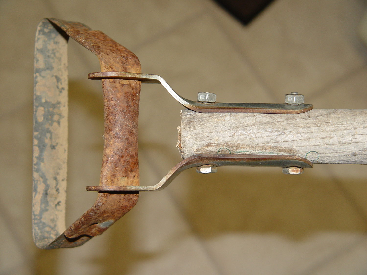
Mary (not the spammer) uses a stirrup hoe for most of what little weeding she does, so it spends much of its life outdoors in the Vassar Farms plot. The bottom of the handle disintegrated and she brought the business end home for repair:
Stirrup hoe – replacement handle
That was easy: a suitable handle lay on the top of the rods-and-tubes rack; I’d harvested it from a defunct rake a while back. Although the wood is weathered, we think of it as well-seasoned. The errant hole marks came from a first pass, before I realized there was no point in having the handle extend beyond the outward-bending part of the brackets.
The bolts and locking nuts are original!
Ya gotta have stuff…
(And not a trace of 3D printing anywhere to be seen. Imagine that!)
This must be the season for scams, as WordPress recently forwarded this message through the Contact form:
My name is Mary. I was just reading Personal 3D Printing: 2014 Status Report – I’m doing some private research on 3D printing and the article is great! I loved images! Great sense of humor and amazing taste in choosing images! :D
But that is not the only reason why I’m writing.
I’m actually writing on behalf of San Francisco Circuits, a PCB solutions provider in Northern California. I came across your site, read some interesting stuff and thought I’d come to you directly and ask if you’re interested in guest posting on Softsolder.com?
We have writers on staff that write articles on circuit design, fabrication, assembly, and everything else PCB related.
The message came from a Croatian IP address: 212.92.194.119
The go8 domain has a placeholder web page. The Petrovic Family Trust probably runs an email server that we’re not privy to; I’d lay long odds they’re blissfully unaware of her account.
SF Circuits probably doesn’t know anything about her, either, and I’m absolutely certain those “staff” writers she touts know exactly squat about “everything else PCB related”.
Should I ask her for writing samples or pointers to their work elsewhere on the Intertubes? How much would they pay to write posts for me? If I had nothing better to do, I’d string her along for a while…
In fact, given how this spam stuff works, I suspect “Mary” isn’t her name and she’s not even female, but I’m never going to know the rest of the story.
One point in her favor, though: she has figured out how to get paid for doing stuff on the Intertubes.
The rise and fall times for the LEDs on the over-the-top blinky taillight left a bit to be desired, at least if you were interested in short pulses:
VG 1193 mV – ID 50 mA-div – 1 ms PWM filter – overview
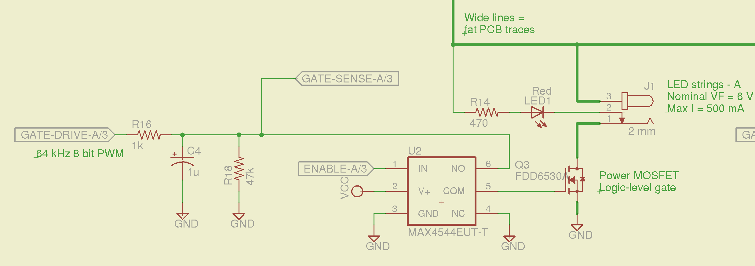
So I spliced an analog switch between the PWM filter and the gate, with inputs selecting ground and the PWM drive voltage:
Switched MOSFET gate – analog switch schematic
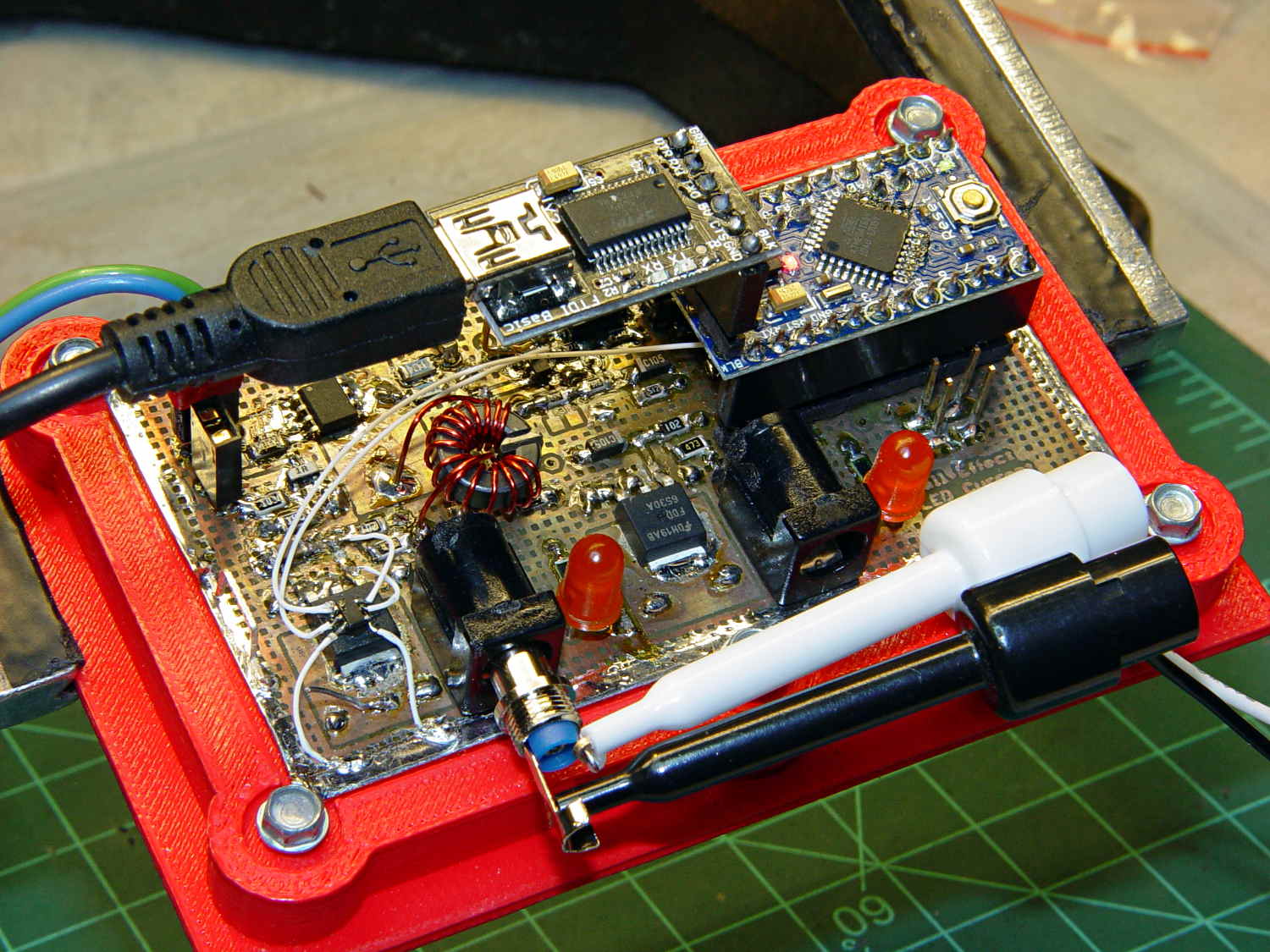
This being a prototype, that involved epoxying a SOT23-6 package atop the MOSFET, with flying wires all over the PCB:
Hall Effect PCB – MOSFET gate switch
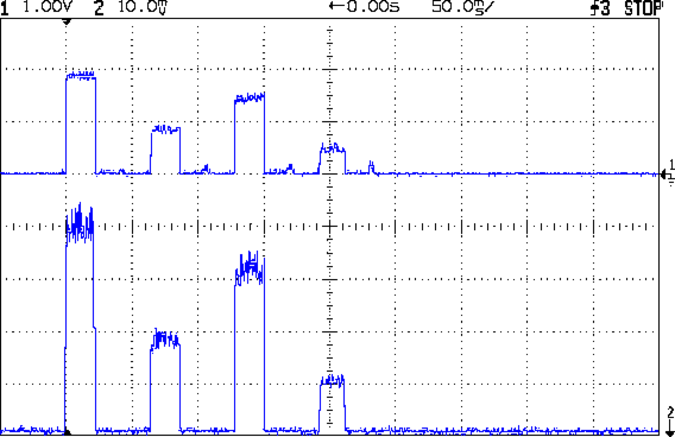
It works pretty well:
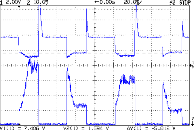
VDS ILED 50 mA div – 200 50 150 25 mA
The top trace is the drain voltage and the bottom trace is the LED current at 50 mA/div.
The current transitions come out vertical at any sweep speed, even through the Tek Hall effect current probe. The pulses would be rectangular if I weren’t changing the current for each one.
The current feedback loop closes through the Arduino’s main loop, which includes a 1 ms delay after each PWM output change before measuring the LED current. As a result, each loop takes just under 2 ms, but, fortunately, ramping from 25 mA (in the last pulse) to 200 mA (in the first pulse) requires less than 10 PWM increments; you can see the stairsteps if you squint.
Next up: bump the PWM to 64 kHz (from 32 kHz) and rip out the pull-down resistor that used to hold the gate near ground when the output floated as an input. That should improve the output ripple caused by the MOSFET’s bias as a perfectly serviceable linear amplifier.
The control loop now fetches durations & currents from an array-of-structs, so I can customize each pulse. An obvious enhancement: remember the gate drive that produced a given current, then restore the corresponding value as the starting PWM setting for each pulse, so the loop begins closer to reality. The gate drive varies with temperature and suchlike, so it can’t be a compile-time constant, but maybe the startup routine could preload the array / list / cache with values taken from a “lamp test”.
Four close-together flashes repeating at about 2 Hz, even with two runt pulses, turn the LEDs into a real eye magnet…