The Smell of Molten Projects in the Morning

Ed Nisley's Blog: Shop notes, electronics, firmware, machinery, 3D printing, laser cuttery, and curiosities. Contents: 100% human thinking, 0% AI slop.

Author: Ed

  • Monthly Image: Bannerman’s Island Arsenal

    We finally took the trip to Bannerman’s Island Arsenal:

    Bannermans Island - Google Satellite View
    Bannermans Island – Google Satellite View

    Back in the day, the only way you could get there was by kayak and that just isn’t my style. Nowadays, the Bannerman Castle Trust runs weekend tour boats and that I can do.

    The view from the dock:

    Bannermans Island Arsenal - from dock
    Bannermans Island Arsenal – from dock

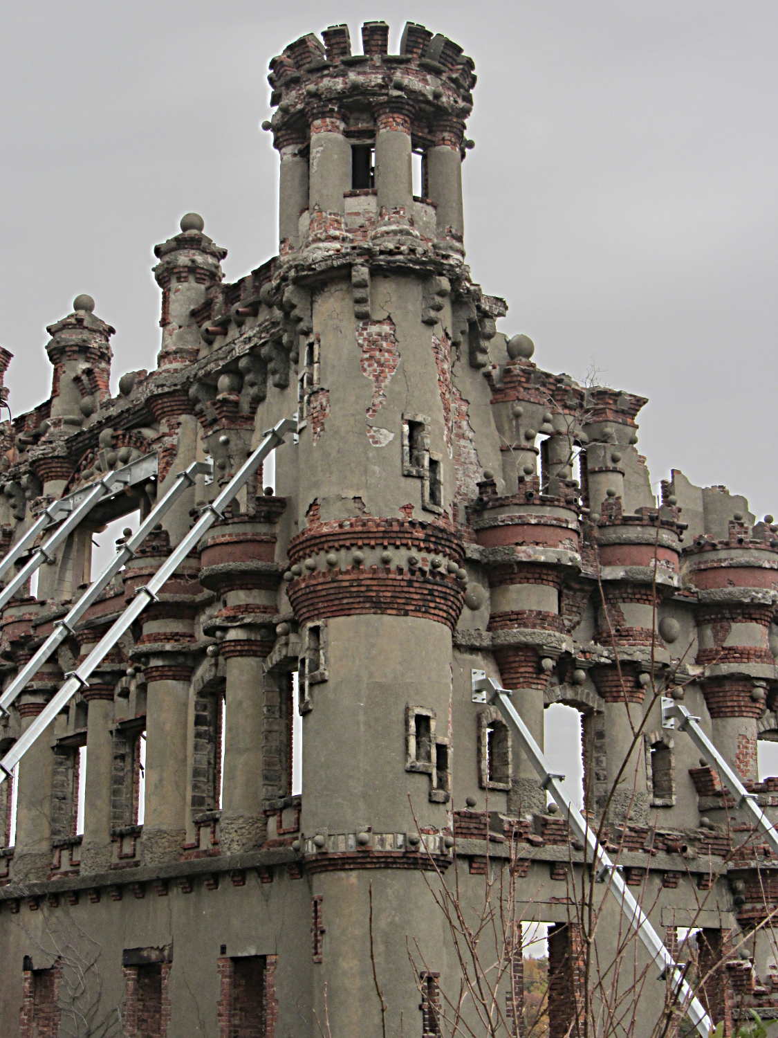
    All the pictures you’ll see of the buildings look the basically the same, because you cannot get off the tour route:

    Bannermans Island - Building Collapse Zone sign
    Bannermans Island – Building Collapse Zone sign

    Of course, that fine might be irrelevant after they dig you out from under the rubble.

    Struts hold the fragile walls in place, but it’s not long for this world:

    Bannermans Island Arsenal - SW corner
    Bannermans Island Arsenal – SW corner

    You can tell that Frank Bannerman got exactly what he wanted in the way of architecture; the buildings bear an uncanny resemblance to his “make it look like this” sketches. In the normal course of a design-and-build project, somebody in the loop will suggest that, mmmm, Boss, you can’t actually build it that way. In this case, the normal course of events went along the lines of “Sir? Yes, Sir!”

    Money changes everything.

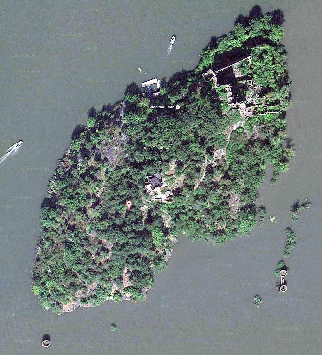
    Their summer house sits dead center in the island with a commanding view of the Hudson to the south. Again, you can tell it looked just exactly like he wanted:

    Bannermans Island - House
    Bannermans Island – House

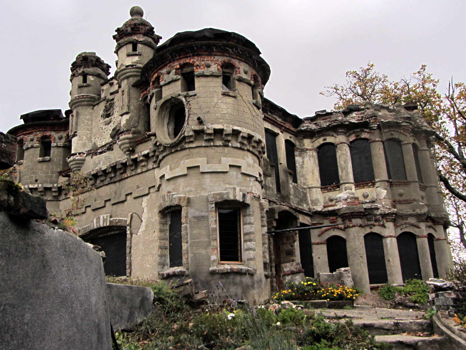
    The natural state of Pollepel Island was barren rock; they hauled in all the soil when Mrs. Bannerman wanted flower gardens around the house.

    That crack in the northwest tower can’t possibly be a Good Thing:

    Bannermans Island Arsenal - W wall
    Bannermans Island Arsenal – W wall

    Back in late 2005, the castle looked marginally better:

    Bannermans Island Arsenal - 2005-10-22
    Bannermans Island Arsenal – 2005-10-22

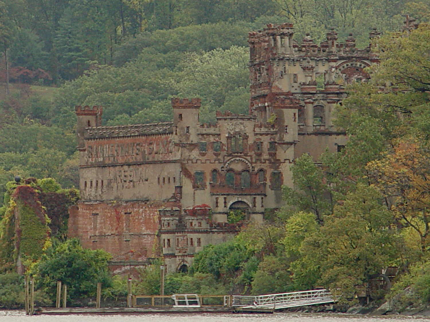
    That was from a small boat in the middle of the Hudson.

    In the unlikely event you’re in the area, take the trip: it’s worthwhile just to see what one man’s obsession looks like. Wear one more layer than you think necessary, put on your lug-soled boots, and realize that nobody’s going to visit the ruins of your summer house a century from now…

  • Kenmore 158: Current Sensor Calibration

    The first task: produce an equation that converts raw ADC values into actual motor current. This is not quite the same as the DC calibration, because the motor current is neither clean nor stable.

    Step the output current setpoint in 50 mA increments from 450 mA to 1100 mA and remain at each setpoint for 10 seconds while dumping measurements every 500 ms. The ADC count comes from the sampling / sorting / selection process that attempts to pick out either the not really flat top of the current-limited waveform or the peak of the non-limited sine wave.

    Convert the raw data dump into a spreadsheet to get a block like this for each current setpoint:

    Motor RPM Shaft RPM Setpoint mA DAC count ADC count Noisy mA Comp mA
    Setpoint: 600 DACvalue: 2372
    3797 334 600 2372 266 724 540
    4465 399 600 2372 263 715 532
    4734 416 600 2372 265 721 538
    4834 438 600 2372 263 715 532
    4829 433 600 2372 264 718 535
    4857 438 600 2372 264 718 535
    4900 438 600 2372 265 721 538
    4859 436 600 2372 266 724 540
    4887 445 600 2372 265 721 538
    4926 446 600 2372 263 715 532
    4884 438 600 2372 265 721 538
    4890 442 600 2372 264 718 535
    4913 440 600 2372 264 718 535
    4866 436 600 2372 263 715 532
    4895 434 600 2372 264 718 535
    4890 442 600 2372 266 724 540
    4884 438 600 2372 266 724 540
    4913 442 600 2372 265 721 538
    4913 441 600 2372 266 724 540
    4878 436 600 2372 264 718 535
    265

    The lone number on the bottom row is the computed average of the ADC counts for the block, which I did in the spreadsheet rather than in the firmware.

    During each ten second interval, set the scope voltage cursor to the eyeballed “correct” value of the motor current waveform, as measured on the Tek current probe. There’s no way to automate this, because only the human eyeball can pick out the, ah, true current measurement amid all the clutter:

    Calibrate - Hall amp - Tek 200 mA-div
    Calibrate – Hall amp – Tek 200 mA-div

    For each current setpoint value, create a line with the manually measured true voltage from the scope trace, the calculated true current (using the Tek probe’s front panel scale), along with the DAC setpoint and the average ADC values extracted from each block of that giant data dump:

    Setpoint mA Scope mV Actual mA DAC count ADC count
    450 21.80 436 2205 197
    500 25.94 519 2261 225
    550 29.06 581 2316 245
    600 31.56 631 2372 265
    650 34.38 688 2427 285
    700 36.88 738 2483 304
    750 39.69 794 2538 324
    800 42.19 844 2594 340
    850 45.00 900 2649 350
    900 47.50 950 2705 361
    850 46.86 937 2649 356
    800 43.75 875 2594 348
    750 41.25 825 2538 335
    700 39.06 781 2483 318
    650 36.56 731 2427 302
    600 34.38 688 2372 285
    550 32.50 650 2316 270
    500 30.31 606 2261 253
    450 27.81 556 2205 237
    400 25.63 513 2150 220

    Plot each actual motor current against the corresponding average ADC value:

    ADC Calibration Curve
    ADC Calibration Curve

    The linear fit breaks down toward 1 A, because measuring the actual peak of a noisy sine wave doesn’t work well, but the values aren’t all that far off.

    Given an ADC value, that equation converts it directly into the actual motor current as estimated by the human eyeball, taking into account all the measurement weirdness. The Hall sensor produces a voltage that’s linearly related to the current, so the reasonable linearity of the data says that the sampling / sorting / selection process actually produces pretty nearly the correct result across the entire operating current range.

    Note that the equation doesn’t depend on the DAC output calibration; the ADC and Tek probe simply measure whatever current happens to pass through the motor for that DAC value. The current through the ET227 transistor doesn’t seem to change over the ten seconds required to take the manual measurement, so it’s all good.

  • Kenmore 158: Current & Shaft Speeds vs. Motor RPM

    Now that the Arduino can set the current limiter, then measure the motor RPM, shaft RPM, and actual motor current, I can make plots like this:

    Shaft speed and motor current vs RPM
    Shaft speed and motor current vs RPM

    The data comes from a routine that increments the setpoint current by 50 mA every five seconds, bouncing off 250 mA on the low end and 1 A on the high end, and writes the values to the serial port every half second. The actual current need not match the setpoint current, because it’s running open loop, and I haven’t done much in the way of calibration, so these represent interesting trends rather than dependable data points.

    The eyeballometric slope down the middle of that blue smear comes out spot on 0.90, making the belt reduction 11.1 in good agreement with the results of those pulses.

    The motor starts turning at 650 mA and will continue running down to maybe 500 mA, but with essentially zero low-end torque.

    The horizontal range of green dots at each current setting shows that, as expected, the setpoint current has only a vague relation to the resulting motor speed: setting 800 mA will produce a speed between 5500 RPM and 9000 RPM, for sure. The actual motor current resulting from a given DAC output depends on the various transistor gains, all of which depend on temperature, which depends on how long the firmware has been running the motor at which speeds. Plenty of variation to go around.

    The red points show that the actual motor current, as measured by the Hall effect sensor, generally lies below the green setpoint values, so better calibration is in order. Temperature effects turn accurate open-loop calibration into a fool’s errand, but we can do better than what you see there.

    However, those red points do cluster much better, particularly between 6000 and 9000 RPM. You still can’t depend on the correlation, though, because the motor runs with a constant load here. In real life, the load will vary and so will the current required to maintain a given speed.

    The green setpoints diverge from the red measurements at the high end, because the current limiter stops having much of an effect when the motor runs flat-out and sets its own current. After all, the original carbon-disk rheostat connected the line voltage directly across the motor, at which point the motor’s 100 W rating comes into play and limits the current to a nice sine wave with 1 A peaks.

    All in all, it looks pretty good…


  • Wasabi NB-5L: Underperformers

    Based on the poor performance of the NB-5L batteries I bought from Blue Nook, they sent me three NB-5L batteries from a fresh batch (date code BNI13) and I ran them through the same discharge test:

    Canon NB-5L - OEM Wasabi - 2014-10-29
    Canon NB-5L – OEM Wasabi – 2014-10-29

    The red line off to the far right is the three year old Canon OEM battery, which remains far and away the best battery at 1 A·h.

    The previous cells (BNF27) produced the three scattered traces with the lowest initial voltages, ending around 0.8 A·h.

    The new cells (BNI13) produced the three tightly clustered traces. They have a higher initial voltage than the OEM cell, but much lower total capacity (about 0.75 A·h).

    These batteries obviously don’t come close to their 1400 mA·h rating. The capacity depends on the load current, but I’m using 500 mA because that’s close to the camera’s drain; the results should correlate reasonably well with actual use.

    The higher voltage from the new batteries will produce a longer runtime than the previous duds, but their total capacity is lower and they’re still no match for the old Canon OEM battery.

    The new ones start out very similar to each other, but the previous batch hasn’t aged well on their shelf. If the date codes mean what I think, all of these batteries will fail quickly.

    All that’s quite disappointing, because their NP-BX1 batteries for the Sony camera turned out quite well. The date codes all have the same format and typography, so I think they come from the same factory.

    For whatever it’s worth, I think the date coding works like this:

    • B – factory? shift? OEM? Blue Nook?
    • M – last two digits of year: M=13, N=14
    • K – month: F=6, I=9, K=11
    • 20 – day 

    For the four batteries / lots I have on hand:

    • BMK20 = 2013 Nov 20 – NP-BX1 bought in early 2014
    • BNI18 = 2014 Sep 18 – NP-BX1 bought in October – new lot
    • BNF27 = 2014 Jun 27 – NB-5L bought in October – old lot
    • BNI13 = 2014 Sep 13 – NB-5L supplied in late October – new lot

    So it goes.

  • Kenmore 158: Bubble Sorted Motor Current Sampling

    Because the ET227 transistor acts as a current limiter, the motor current waveform has flat tops at the level set by the DAC voltage. However, the current depends strongly on the temperature of all those transistor junctions, with some commutation noise mixed in for good measure, so the firmware must measure the actual current to know what’s going on out there.

    Here’s one way to pull that off:

    Motor current - ADC sample timing
    Motor current – ADC sample timing

    The upper waveform shows the motor current sporting flat tops at 650 mA.

    The lower waveform marks the current measurement routine, with samples taken just before the falling edge of the first nine pulses. The (manually tweaked) delay between the samples forces them to span one complete cycle of the waveform, but they’re not synchronized to the power line. Remember that the motor runs from a full wave rectifier, so each “cycle” in that waveform is half of a normal power line cycle.

    Given an array containing those nine samples, the routine must return the maximum value of the waveform, ignoring the little glitch at the start of the flat top and taking into consideration that the waveform won’t have a flat top (or much of a glitch) when the current “limit” exceeds the maximum motor current.

    After a bit of fumbling around with the scope and software, the routine goes like this:

    • Collect samples during one current cycle
    • Sort in descending order
    • Ignore highest sample
    • Return average of next two highest samples

    Given that the array has only nine samples, I used a quick-and-dirty bubble sort. The runt pulse at the end of the series in the bottom waveform brackets the sort routine, so it’s not a real time killer.

    Seeing as how this is one of the very few occasions I’ve had to sort anything, I wheeled out the classic XOR method of exchanging the entries. Go ahead, time XOR against swapping through a temporary variable; it surely doesn’t make any difference at all on an 8-bit microcontroller.

    The sampling code, with all the tracing stuff commented out:

    //------------------
    // Sample current along AC waveform to find maximum value
    //	this is blocking, so don't call it every time around the main loop!
    
    #define NUM_I_SAMPLES	9
    
    unsigned int SampleCurrent(byte PinNum) {
    	
    unsigned int Samples[NUM_I_SAMPLES];
    unsigned int AvgSample;
    byte i,j;
    	
    //	digitalWrite(PIN_SYNC,HIGH);
    	for (i=0; i < NUM_I_SAMPLES; i++) {				// collect samples
    //		digitalWrite(PIN_SYNC,HIGH);
    		Samples[i] = ReadAI(PinNum);
    //		digitalWrite(PIN_SYNC,LOW);
    		delayMicroseconds(640);
    	}
    //	digitalWrite(PIN_SYNC,LOW);
    	
    //	digitalWrite(PIN_SYNC,HIGH);							// mark start of sorting
    	for (i=0; i < (NUM_I_SAMPLES - 1); i++)
    		for (j=0 ; j < (NUM_I_SAMPLES - 1 - i); j++)
    			if (Samples[j] < Samples[j+1]) {
    				Samples[j] ^= Samples[j+1];					// swap entries!
    				Samples[j+1] ^= Samples[j];
    				Samples[j] ^= Samples[j+1];
    			}
    //	digitalWrite(PIN_SYNC,LOW);								// mark end of sorting
    	
    //	printf("Samples: ");
    //	for (i=0; i < NUM_I_SAMPLES; i++)
    //		printf("%5d,",Samples[i]);
    	
    	AvgSample = (Samples[1] + Samples[2])/2;				// discard highest sample
    //	printf(" [%5d]\r\n",AvgSample);
    	
    	return AvgSample;
    
    }
    
  • Kenmore 158: Motor RPM Sensor Deglitching

    The setscrew in the motor pulley lies directly in the path of the photosensor:

    TCTR5000 Motor RPM Sensor - side view
    TCTR5000 Motor RPM Sensor – side view

    Which produces a glitch in the rising edge of the digital output as the pulley rotates from the dark to the light section:

    Motor Sensor - Rising Edge Glitch
    Motor Sensor – Rising Edge Glitch

    The RPM signal goes to Arduino pin D2, where each falling edge triggers an interrupt handler:

    const byte PIN_MOTOR_REV = 2;		// DI - IRQ 0 (must be D2)
    
    ... snippage...
    
    void setup() {
    ... snippage ...
    
        pinMode(PIN_MOTOR_REV,INPUT_PULLUP);
        attachInterrupt((PIN_MOTOR_REV - 2),ISR_Motor,FALLING);			// one IRQ / motor revolution
    
     ... snippage ...
    }
    

    The maximum motor speed is about 11 kRPM, so interrupts should be at least 5.5 ms apart and the digital input should be low. If that’s true, then the code updates a bunch of useful information:

    struct pulse_t {
     byte Counter;
     unsigned long TimeThen;
     unsigned long Period;
     word RPM;
     byte State;
    };
    
    struct pulse_t Motor;
    
    ... snippage ...
    
    //------------------
    // ISR to sample motor RPM sensor timing
    
    void ISR_Motor(void) {
    
    static unsigned long Now;
    
    	digitalWrite(PIN_SYNC,HIGH);
    
    	Now = micros();
    
    	if ((5000ul < (Now - Motor.TimeThen)) && !digitalRead(PIN_MOTOR_REV) ) {	// discard glitches
    		Motor.Counter++;
    		Motor.Period = Now - Motor.TimeThen;
    		Motor.TimeThen = Now;
    		Motor.State = digitalRead(PIN_MOTOR_REV);		// always zero in a Physics 1 world
    	}
    
    	digitalWrite(PIN_SYNC,LOW);
    	return;
    }
    

    The scope trace shows that the handler takes about 7 µs to get control after the glitch (the left cursor should be on the falling edge, not the rising edge), so the input read occurs when the sensor output is over 4.5 V, causing the handler to discard this spurious interrupt.

    Because Motor.Period is a four-byte unsigned long, the Arduino’s CPU must handle it in chunks. Rather than disable interrupts around each use, it’s better to read the value until two successive copies come back identical:

    //------------------
    // Return current microsecond period without blocking ISR
    
    unsigned long ReadTime(struct pulse_t *pTime) {
    
    unsigned long Sample;
    
    	do {
    		Sample = pTime->Period;				// get all four bytes
    	} while (Sample != pTime->Period);		//  repeat until not changed by ISR while reading
    
    	pTime->Counter = 0;						// this is a slight race condition
    
    	return Sample;
    }
    

    Because the interrupts don’t happen that often, the loop almost always executes only one time. On rare occasions, it’ll go back for another two values.

    Converting the pulley rotation period into revolutions per minute goes like this:

    		Motor.RPM = 60000000ul/ReadTime(&Motor);		// one (deglitched) pulse / rev
    

    That’s easier than hiding the setscrew and it also discards any other glitches that may creep into D2

  • Praying Mantis

    A praying mantis appeared along the top of the living room windows:

    Praying mantis on window
    Praying mantis on window

    They’re ferocious hunters and we’re in favor of them… but having them on the outside of the window works better for all of us.

    Those old Anderson windows seem to attract big critters