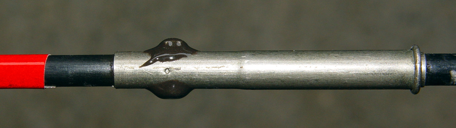
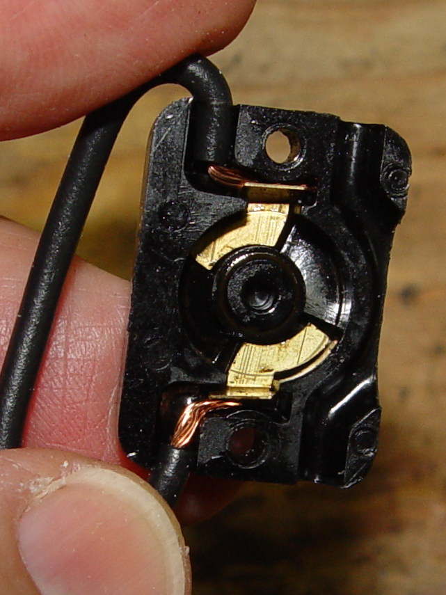
We agreed that repairing the failed flag ferrule made the trailer much quieter, but it still seemed far more rattly than we remembered. It just had to be the fender, somehow, and eventually this appeared:
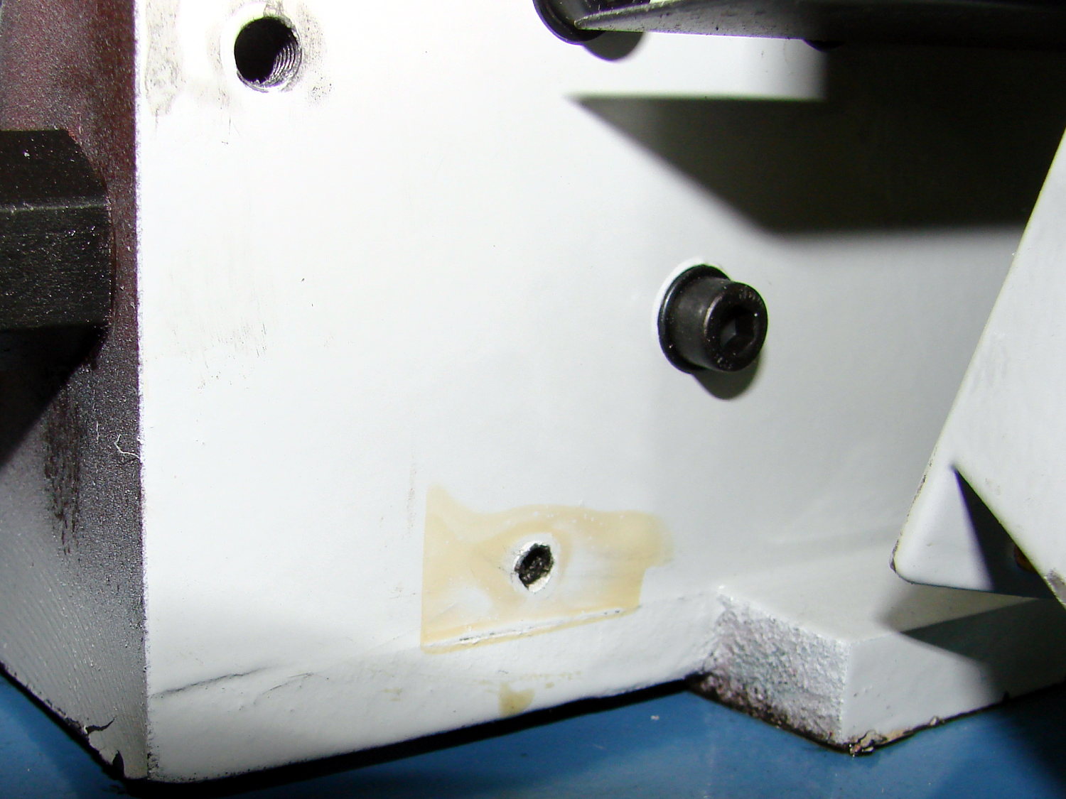
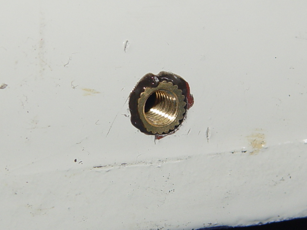
The obviously missing piece of the fender fell out in my hand; the similar chunk just beyond the wire arch fell out after I took the pictures. Yes, the wire has indented the fender.
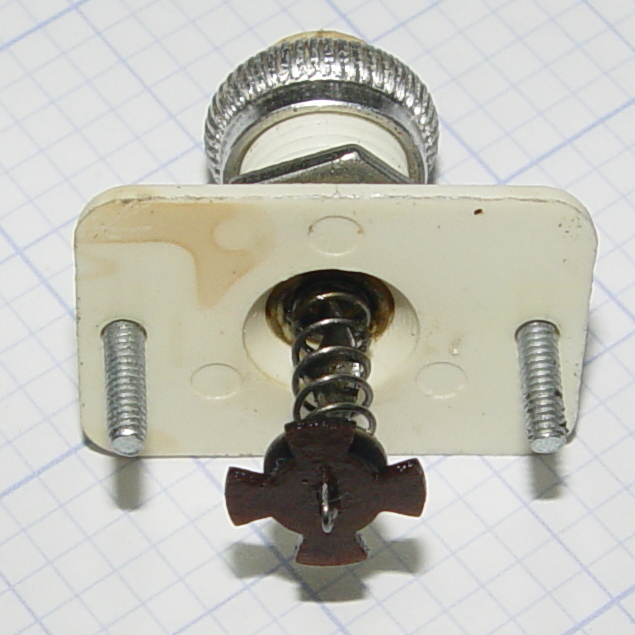
The arch supports the aluminum fender, with a pair of (flat) steel plates clamping the wire to the fender:
The cardboard scraps show I fixed a rattle in the distant past.
Being aluminum, the fender can’t have a replacement piece brazed in place and, given the compound curves, I wasn’t up for the requisite fancy sheet metal work.
Instead, a bit of math produces a pair of shapes:
In this case, we know the curve radii, so the chord equation gives the depth of the curve across the (known) width & length of the plates; the maximum of those values sets the additional thickness required for the plates. The curves turn out to be rather steep, given the usual layer thickness and plate sizes, which gives them a weird angular look that absolutely doesn’t matter when pressed firmly against the fender:
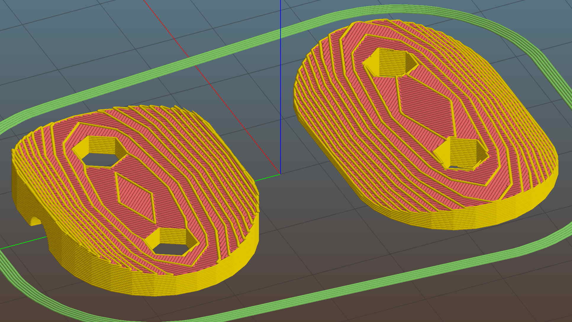
The computations required to fit Hilbert Curve surface infill into those small exposed areas took basically forever; given that nobody will ever see them, I used the traditional linear infill pattern. A 15% 3D Honeycomb interior infill turned them into rigid parts.
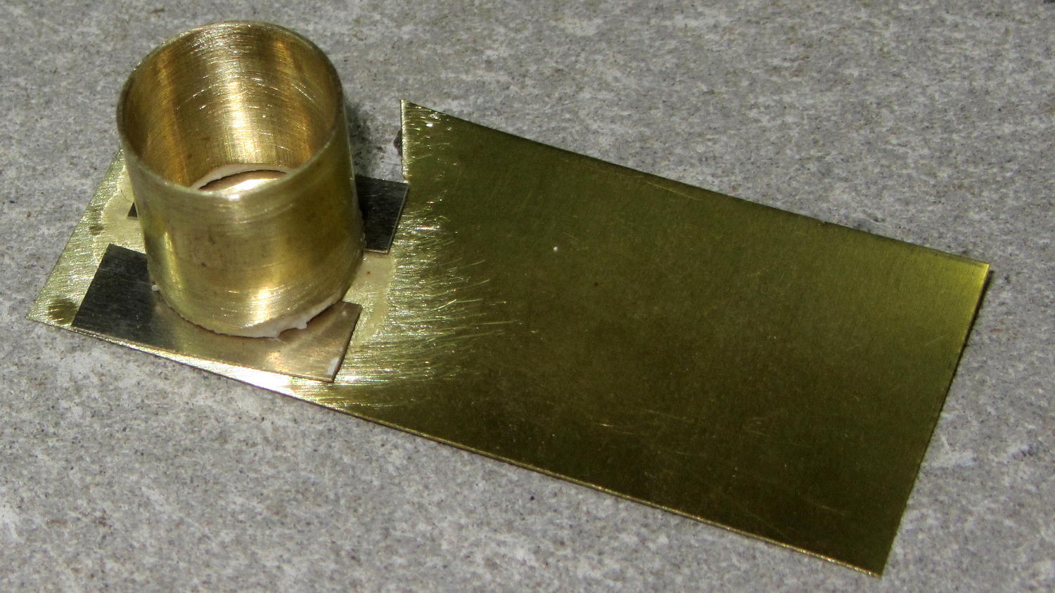
The notch in the outer plate (top left, seen notch-side-down) accommodates the support wire:

The upper surface would look better with chamfered edges, but that’s in the nature of fine tuning. That part must print with its top surface downward: an unsupported (shallow) chamfer would produce horrible surface finish and life is too short for fussing with support. Given the surrounding rust & dings, worrying about aesthetics seems bootless.
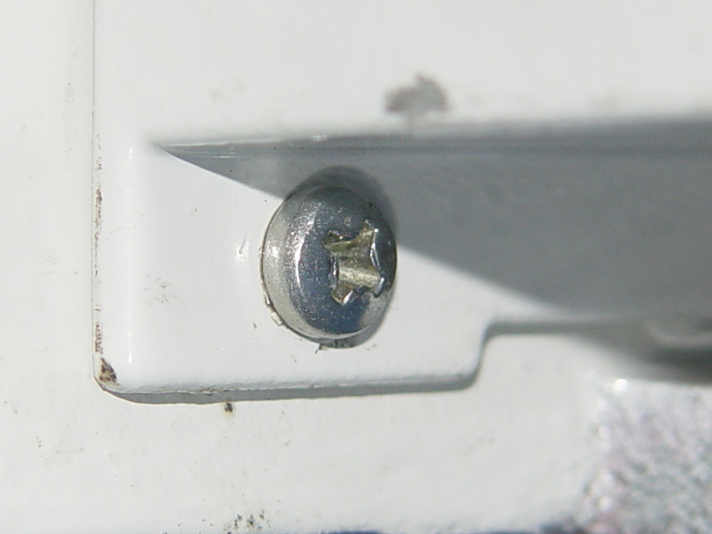
The original screws weren’t quite long enough to reach through the plastic plates, so I dipped into my shiny-new assortment of stainless steel socket head cap screws. Although the (uncut) M5x16 screws seem to protrude dangerously far from the inner plate, there’s another inch of air between those screws and the tire tread:

Given the increase in bearing area, that part of the fender shouldn’t fracture for another decade or two.
I loves me my M2 3D printer …
The OpenSCAD source code as a GitHub Gist:
| // BOB Yak Fender Mounting Bracket | |
| // Ed Nisley – KE4ZNU – July 2016 | |
| Layout = "Build"; // Build Fender Rod BlockInner BlockOuter | |
| //- Extrusion parameters must match reality! | |
| // Print with 1 shell and 3 solid layers | |
| ThreadThick = 0.25; | |
| ThreadWidth = 0.40; | |
| HoleWindage = 0.3; | |
| Protrusion = 0.1; // make holes end cleanly | |
| inch = 25.4; | |
| //———————- | |
| // Dimensions | |
| IR = 0; // radii seem easier to measure here | |
| OR = 1; | |
| LENGTH = 2; | |
| Fender = [25,220,1]; // minor major thickness | |
| FenderSides = 128; | |
| FenderRod = [5.0/2,(Fender[IR] + 10),5.0/2]; // support rod dia/2, arch radius, rod dia/2 again | |
| ChordMajor = Fender[OR] – sqrt(pow(Fender[OR],2) – pow(40,2)/4); | |
| ChordMinor = Fender[IR] – sqrt(pow(Fender[IR],2) – pow(25,2)/4); | |
| ChordFit = max(ChordMajor,ChordMinor); | |
| echo("Chords: ",ChordMajor,ChordMinor,ChordFit); | |
| BlockInnerOA = [40,25,1 + ChordFit]; | |
| BlockOuterOA = [35,25,2 + ChordFit]; | |
| echo(str("Inner Block: ",BlockInnerOA)); | |
| echo(str("Outer Block: ",BlockOuterOA)); | |
| ScrewOD = 5.0; | |
| ScrewOC = 20.0; | |
| NumSides = 6*4; | |
| //———————- | |
| // Useful routines | |
| module PolyCyl(Dia,Height,ForceSides=0) { // based on nophead's polyholes | |
| Sides = (ForceSides != 0) ? ForceSides : (ceil(Dia) + 2); | |
| FixDia = Dia / cos(180/Sides); | |
| cylinder(r=(FixDia + HoleWindage)/2, | |
| h=Height, | |
| $fn=Sides); | |
| } | |
| module FenderShape() { | |
| rotate([90,0*180/FenderSides,0]) | |
| rotate_extrude(angle=180,$fn=FenderSides) | |
| translate([(Fender[OR] – Fender[IR]),0]) | |
| circle(r=Fender[IR],$fn=2*NumSides); | |
| } | |
| module RodShape() { | |
| rotate([90,0*180/FenderSides,0]) | |
| rotate_extrude(angle=180,convexity=2,$fn=FenderSides) | |
| translate([(FenderRod[OR] – FenderRod[IR]),0]) | |
| circle(r=FenderRod[IR],$fn=NumSides); | |
| } | |
| module BlockInner() { | |
| intersection() { | |
| difference() { | |
| linear_extrude(height=BlockInnerOA[LENGTH],convexity=3) | |
| hull() { | |
| for (i=[-1,1]) | |
| translate([i*(BlockInnerOA[0]/2 – BlockInnerOA[1]/2),0,0]) | |
| circle(d=BlockInnerOA[1]); | |
| } | |
| for (i=[-1,1]) | |
| translate([i*(ScrewOC/2),0,-Protrusion]) | |
| PolyCyl(ScrewOD,2*BlockInnerOA[2],6); | |
| } | |
| translate([0,0,(BlockInnerOA[2] – Fender[OR])]) | |
| FenderShape(); | |
| } | |
| } | |
| module BlockOuter() { | |
| difference() { | |
| linear_extrude(height=BlockOuterOA[LENGTH],convexity=4) | |
| hull() { | |
| for (i=[-1,1]) | |
| translate([i*(BlockOuterOA[0]/2 – BlockOuterOA[1]/2),0,0]) | |
| circle(d=BlockOuterOA[1]); | |
| } | |
| for (i=[-1,1]) | |
| translate([i*(ScrewOC/2),0,-Protrusion]) | |
| PolyCyl(ScrewOD,2*BlockOuterOA[2],6); | |
| translate([0,0,(BlockOuterOA[2] – ChordFit + Fender[OR])]) | |
| rotate([180,0,0]) | |
| FenderShape(); | |
| translate([0,0,(FenderRod[OR] – 2*FenderRod[IR])]) | |
| rotate([180,0,90]) | |
| RodShape(); | |
| } | |
| } | |
| //- Build things | |
| if (Layout == "Fender") | |
| FenderShape(); | |
| if (Layout == "Rod") | |
| RodShape(); | |
| if (Layout == "BlockInner") | |
| BlockInner(); | |
| if (Layout == "BlockOuter") | |
| BlockOuter(); | |
| if (Layout == "Build") { | |
| translate([0,-BlockInnerOA[0]/2,0]) | |
| BlockInner(); | |
| translate([0,BlockOuterOA[0]/2,0]) | |
| BlockOuter(); | |
| } | |
The original dimension measurement and design doodle: