The Smell of Molten Projects in the Morning

Ed Nisley's Blog: Shop notes, electronics, firmware, machinery, 3D printing, laser cuttery, and curiosities. Contents: 100% human thinking, 0% AI slop.

Author: Ed

  • LF Crystal Tester: 60 kHz Resonator Frequency Distribution

    Histogramming all 50-ish resonator frequencies shows reasonably good distributions:

    Notably, there’s no obvious suckout in the middle, as with those eBay Hall-effect sensors.

    60 kHz Resonant Frequencies - CX 24 pF - histogram
    60 kHz Resonant Frequencies – CX 24 pF – histogram

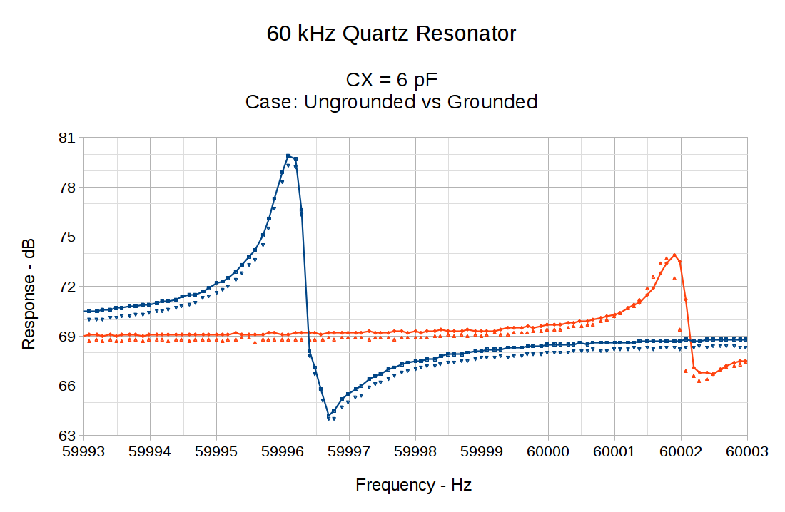
    I don’t know what to make of the difference between the parallel series-capacitor and basic serial resonant frequencies for each tuning fork:

    60 kHz Resonant Frequencies - CX 24 pF - delta histogram
    60 kHz Resonant Frequencies – CX 24 pF – delta histogram

    Perhaps each resonator’s frequency depends on its (laser-trimmed) tine mass and follows a more-or-less normal distribution, but the parallel-serial difference series capacitor changes the frequency based on (well-controlled) etched dimensions producing quantized results from three different masks / wafers / lots, with the motional inductance and capacitance incompletely modeling the physics?

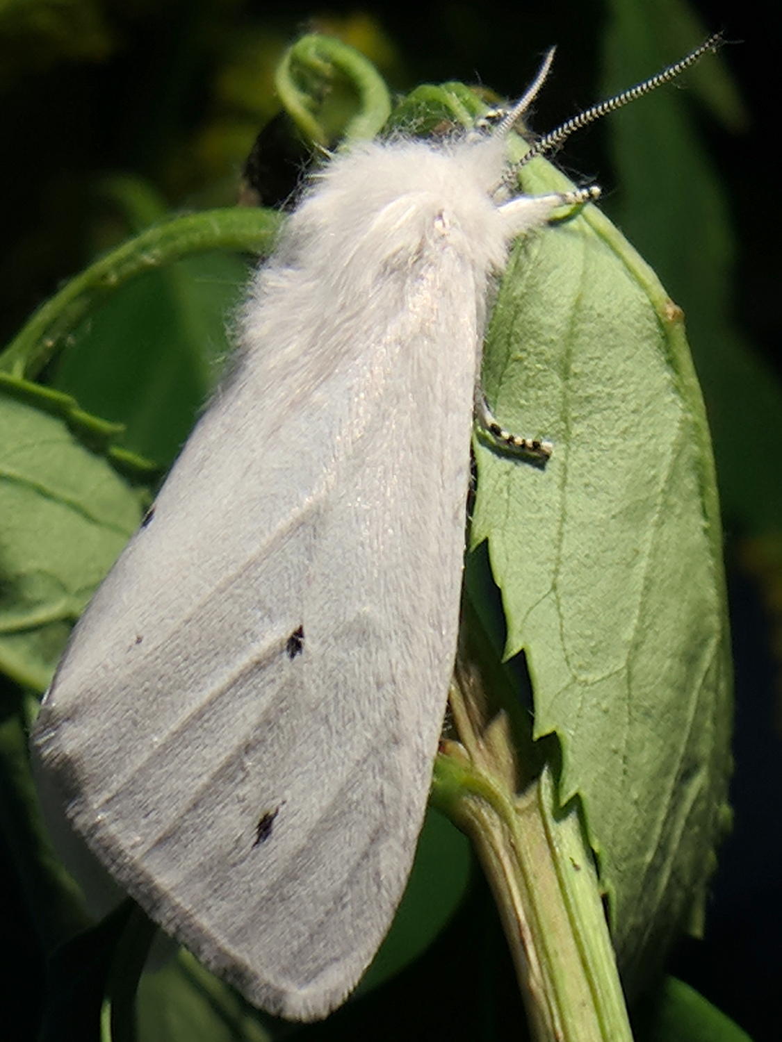
    For reference, the resonators look like this:

    Quartz resonator - detail
    Quartz resonator – detail

    Producing the histograms uses the LibreOffice frequency() array function, which requires remembering to whack Ctrl-Shift Enter to activate the function’s array-ness.

    [Update: Faceplant about “parallel” resonance, which is actually the shifted resonant peak due to the 24 pF series cap. Apparently I typo-ed the second histogram subheading and ran with the error; the figures are now correct.]

  • LF Crystal Tester: Grounded CX Case

    The usual model for a quartz resonator apportions half the measured both-leads-to-case capacitance to each lead:

    AT26 crystal capacitance fixture - Cpar detail
    AT26 crystal capacitance fixture – Cpar detail

    These AT26 / TF26 cases run around 0.6 pF, so each parasitic capacitor is 300 fF:

    60 kHz Quartz Resonator - model
    60 kHz Quartz Resonator – model

    For ordinary quartz crystals, you solder the case to the ground plane to get rid of the sneak path around the central capacitor (normally C0, but labeling it properly in LTSpice just isn’t happening), but those little aluminum cans aren’t solderable. One could blob some Wire Glue over them, but …

    So I just wrapped a wire around the case and soldered it to a convenient ground point under the board:

    LF Crystal Tester - grounded TF26 case
    LF Crystal Tester – grounded TF26 case

    Aaaand ran the obvious measurements:

    60 kHz Quartz Resonator 0 - CX 6 pF - grounded vs float
    60 kHz Quartz Resonator 0 – CX 6 pF – grounded vs float

    Solid lines = case ungrounded. Dotties = case grounded.

    Grounding the case knocks the off-peak response down by less than 1 dB. The on-peak response remains about the same, so eliminating the series capacitance does reduce the blowthrough.

    With the case grounded and CX = 6 pF in the circuit, the peaks over on the right seem ever so slightly lower in frequency, which suggests a slightly higher motional capacitance. There’s not much to write home about, though, so I’d say there’s very little effect, even on this scale.


  • LF Crystal Tester: Resonance Frequencies vs CX

    Adjusting the series capacitor produces pretty much the expected results, with the parallel resonance still tracking the series peak.

    CX = 19.3 pF
    Fs peak: 59996.18 Hz 80.4 dbV
    Fc peak: 59998.19 Hz 78.2 dbV
    Delta frequency: 2.01

    60 kHz Quartz Resonator 0 - CX 19.3 pF
    60 kHz Quartz Resonator 0 – CX 19.3 pF

    CX = 9.9pF
    Fs peak: 59996.19 Hz 79.4 dbV
    Fc peak: 59999.97 Hz 75.8 dbV
    Delta frequency: 3.78

    60 kHz Quartz Resonator 0 - CX 9.9 pF
    60 kHz Quartz Resonator 0 – CX 9.9 pF

    CX = 6.8 pF
    Fs peak: 59996.10 Hz 80.3 dbV
    Fc peak: 60001.48 Hz 74.6 dbV
    Delta frequency: 5.38

    60 kHz Quartz Resonator 0 - CX 6.8 pF
    60 kHz Quartz Resonator 0 – CX 6.8 pF

    At the frequency resolution of these graphs, none of the standard equations are helpful; this is definitely a “tune for best picture” situation.

    So, assuming the same general conditions apply in a filter, a series capacitance around 10 pF should pull the resonant peak to 60.000 kHz. Unfortunately, the cheery 76 dB level is relative to the AD8310‘s nominal -108 dBV intercept at 4 μV: the log amp sees 25 mV after the MAX4255 op amp applies 40 dB (×100) of gain to the 250 μV coming from the resonator. The resonator drive is 1 μW = 150 mV, so the resonator produces a 55 dB loss for a signal dead on frequency.

    The off-peak attenuation looks like a mere 7 dB, although I hope plenty of noise masks the true result in this circuit.

    Phew & similar remarks.

  • Google Pixel XL Camera Oddity: LED Flicker Stripes

    The Pixel’s camera shows a black stripe across both the live preview and the final image:

    Pixel XL Camera - shutter stripe
    Pixel XL Camera – shutter stripe

    That’s under the high-intensity LED lamp on my desk, which must have a high-frequency flicker. I’m amazed the camera remains in absolutely stable sync with the flicker for as long as I’m willing to aim it.

    The stripe covers only the moth and greenery, not the LCD monitor in the background, so it’s caused by the overhead lamp, not something internal to the Pixel or its camera.

    A closer look shows shading on either side of the deepest black (clicky for more dots):

    Pixel XL Camera - shutter stripe - detail
    Pixel XL Camera – shutter stripe – detail

    The stripe location and width differ based on the image zoom level, although in no predictable way:

    Pixel XL Camera - shutter stripe - 2
    Pixel XL Camera – shutter stripe – 2

    The Pixel camera definitely doesn’t have optical zoom, so it’s surely related to the scaling applied to convert the physical sensor array into the final image. Even though all images have 4048×3036 pixels (or the other way around, at least for these portrait-layout pix), zoomed images get made-up (pronounced “interpolated”) data in their pixels.

    Not a problem under any other illumination I’ve encountered so far, so it’s likely something to do with this specific and relatively old LED lamp.

  • Turkey Vultures on a Rainy Day

    These vultures decided to hang out high atop our neighbor’s tree during a recent day-long rainstorm:

    Turkey Vultures - rainy day
    Turkey Vultures – rainy day

    There may be a third vulture on the branch behind the big clump of pine cones near the trunk.

    This seems about as disgusted as a vulture can appear:

    Turkey Vultures - rainy day - detail
    Turkey Vultures – rainy day – detail

    I think that’s a young vulture, without the red face of more mature specimens.

    They spent most of the day there, then flew off about their business. We’re sure they spent most of the next day drying out.

    Taken with the (new-to-me) DSC-H5 and 1.7× teleadapter; no extra charge for the purple fringes.

  • Mystery Caterpillar Revealed: Spilosoma virginica

    The Mystery Caterpillars emerged from their cocoons over the course of several days, whereupon we finally identified them as Yellow Bear caterpillars who became Virginia Tiger Moths.

    Moth 1, with wonderful antenna fringes identifying him as a male:

    Spilosoma virginica 1 - right
    Spilosoma virginica 1 – right

    Moth 2, a female with smaller antenna:

    Spilosoma virginica 2 - right
    Spilosoma virginica 2 – right

    Moth 3, another male:

    Spilosoma virginica 3 - dorsal
    Spilosoma virginica 3 – dorsal

    The underside is diagnostic (ignore the crud on the aquarium glass):

    Spilosoma virginica 3 - ventral
    Spilosoma virginica 3 – ventral

    We set each one on the goldenrod plant inside the garden gate, whereupon they charged up in the sun for an hour or so, then flew off about their business. They may eat a few leaves in the garden, but they’re not particularly harmful to anything and entitled to a peaceful life.

    I must organize all their pictures into a life history.

  • LF Crystal Tester: Variable CX

    Replacing the 22 pF series capacitor with a variable cap went smoothly after I got over having to rip-and-replace the adjacent socket and header, too:

    LF Crystal Tester - variable CX
    LF Crystal Tester – variable CX

    The circuit remains the same, plus a test point to simplify measuring the actual capacitance:

    Test Fixture - variable CX
    Test Fixture – variable CX

    I didn’t add a jumper to disconnect the crystal fixture, because (I think) it would add too much uncontrolled stray capacitance: removing the header would disconnect the socket / header wires.

    The little red cap adjusts from (nominally) 3 pF to 28 pF over half a turn, without a stop. The rotor does have a marked side, but basically you’re supposed to tune for best picture and leave it at that.

    The AADE L/C meter works fine, but in the low pF range everything affects the reading. The only way to measure the actual capacitance seems to be:

    • Clip one lead to the top of the 24 Ω terminating resistor
    • Hold the other within a millimeter of the test point pin
    • Zero the meter, note any residual offset
    • Touch clip lead to test pin
    • Note reading, mentally subtract residual offset

    The as-installed range spans 6.5 pF to 28 pF. I think I can measure it to within ±0.05 pF, with a considerable dependence on maintaining the same pressure on the clip lead.

    I suppose if you were doing this for real, you’d throw another Teledyne relay at the problem.