The Smell of Molten Projects in the Morning

Ed Nisley's Blog: Shop notes, electronics, firmware, machinery, 3D printing, laser cuttery, and curiosities. Contents: 100% human thinking, 0% AI slop.

Author: Ed

  • MPCNC: Bar Clamps

    Using various prototypes of the bar clamp mounts, here’s the left-side clamp in action:

    MPCNC - bar clamp trial installation
    MPCNC – bar clamp trial installation

    In round numbers, the (yet to be installed) spindle won’t exert any upward force worth mentioning, so clamping the material in the horizontal plane should hold it firmly enough for my simple needs. A more robust router needs more downward force.

    The left-side clamp sits outside the MPCNC’s frame to prevent blocking the leftmost inch or so of the work area:

    MPCNC - bar clamp left
    MPCNC – bar clamp left

    Although the right-side clamp is inside the frame rails, the gantry’s asymmetry puts the clamp outside of the work area:

    MPCNC - bar clamp right
    MPCNC – bar clamp right

    Yes, those are nylon bolts; my 1/4-20 bolt stash is greatly depleted. I picked up a small assortment of stainless bolts in useful sizes, but they top out at 1-½ inch.

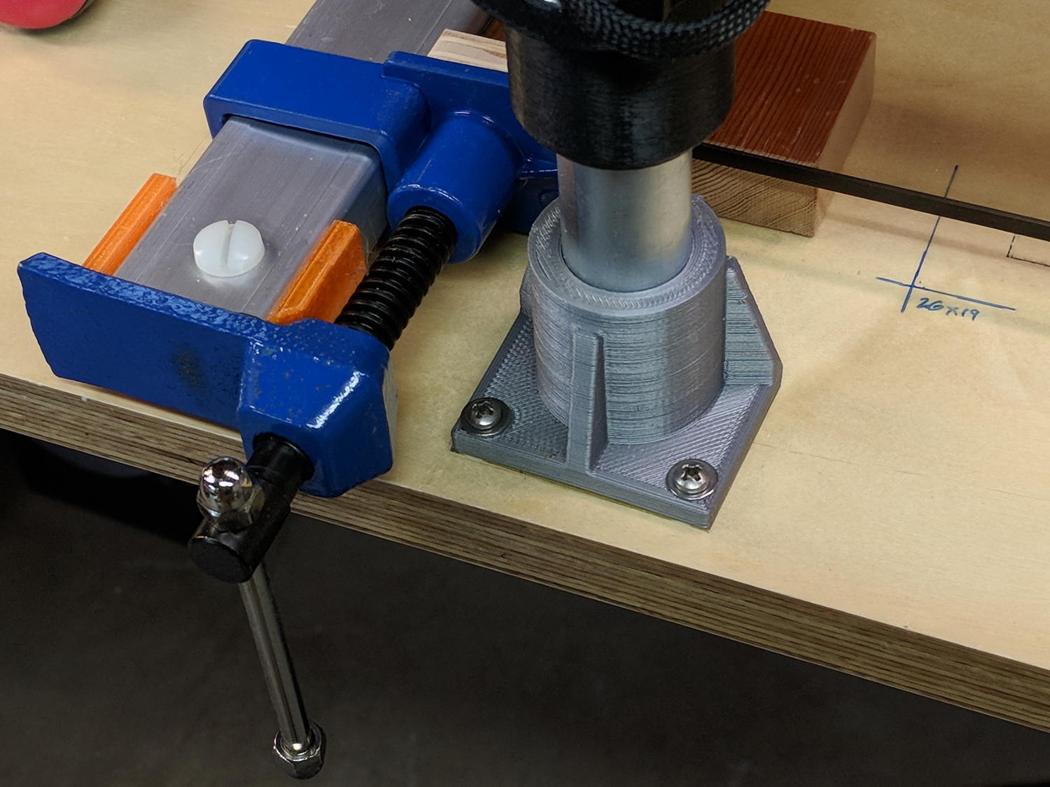
    Fastening the blocks to the bench required a bit of fiddling after squaring the bars against the edge. Transfer-punch the hole location, then drill a 1/16 inch pilot hole:

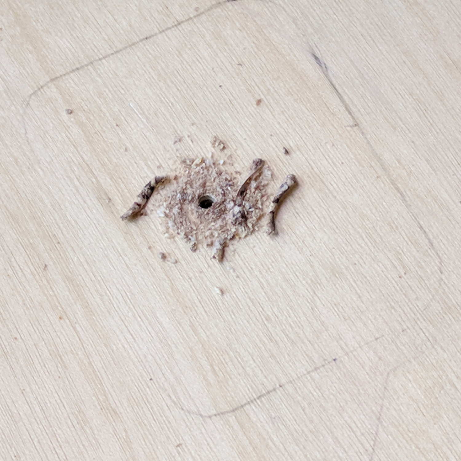
    Gingerly counterbore a t-nut recess in the bottom with a 3/4 inch Forstner bit marked with a suitable depth to completely sink the t-nut:

    MPCNC - t-nut counterbore
    MPCNC – t-nut counterbore

    The shop vac snout keeps the chips out of your face. Works like a champ!

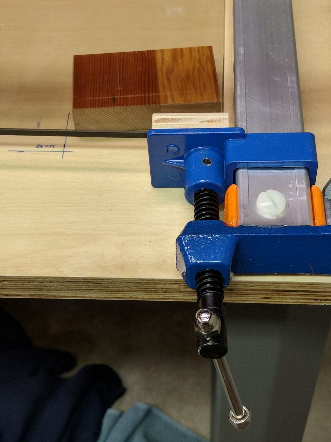
    Redrill the pilot hole with a 5/16 inch brad-point bit to fit the 1/4-20 t-nut body:

    MPCNC - t-nut in counterbore
    MPCNC – t-nut in counterbore

    The t-nut may not be exactly centered in the counterbore, but nobody will ever notice.

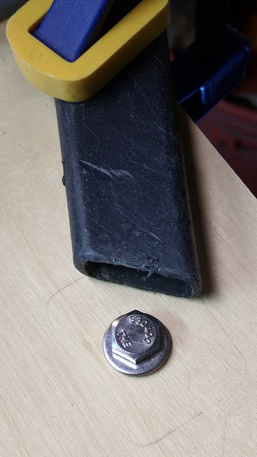
    Rather than hammering the t-nut into the bench, gently & quietly pull it in place with a bolt atop a pair of washers:

    MPCNC - bolt for t-nut installation
    MPCNC – bolt for t-nut installation

    Again, the shop vac collected all the chips from the brad-point bit.

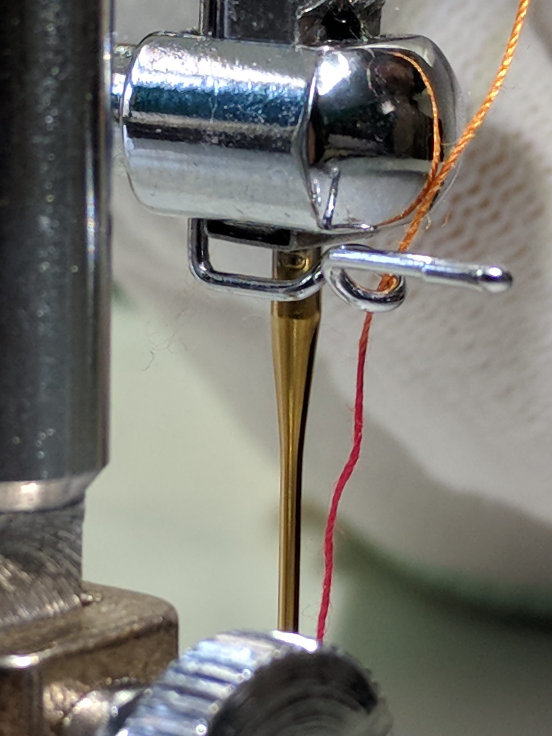
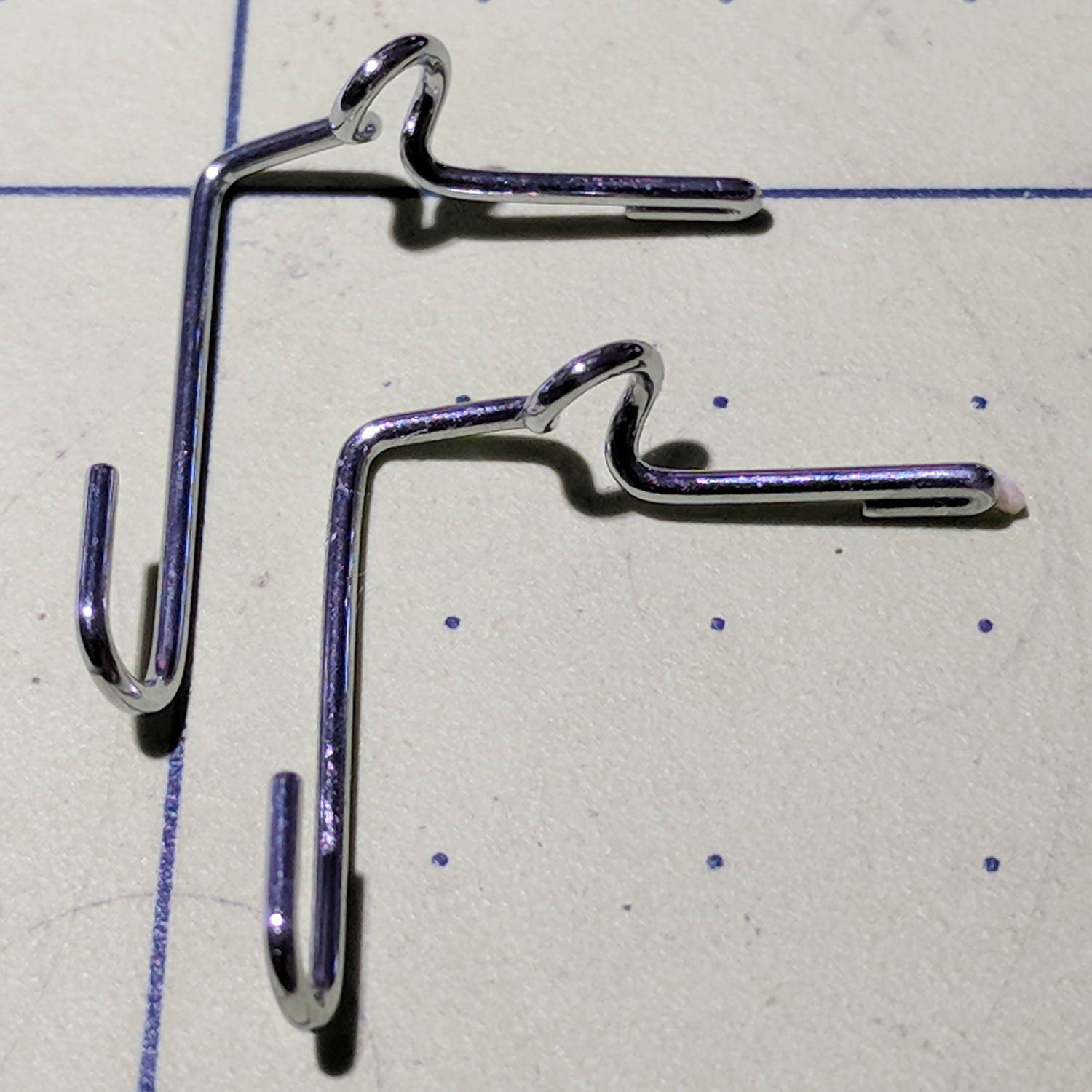
    Of course, Harbor Freight bar clamps aren’t intended for this duty, so they’re held together with assemble-only pins and clips. Disassemble the clip with a Dremel cutoff wheel and the pin will fall right out:

    Bar Clamp - pin removal
    Bar Clamp – pin removal

    I had to through-drill the bar + hardware + 3D printed mount to get a consistent hole, as the overall tolerances aren’t particularly tight and things tend to not fit back together the way they came apart.

    The bar clamps started out at 36 inches and stuck out over the far end of the bench. I hacksawed them to a suitable length, cleaned up the cut on the bandsaw, and the cut disappears in the end block:

    MPCNC - bar clamp end block
    MPCNC – bar clamp end block

    By complete coincidence, the rear bolt holes turned out to be exactly lined up with the edge of the metal bench frame, so I had to remove eleven of the twelve screws holding the bench to the frame, rotate it slightly, drill the rear holes, install the t-nuts, un-rotate the top, and reinstall all the screws. As it turns out, the four end screws are located in blind parts of the frame where I could remove three of them, but cannot re-install them with any tool at my command. I think I can conjure a modified finger wrench, but …

    The bars are made of the softest aluminum known to man in the thinnest cross-section that won’t crumple under a stiff glance, so they’re more flexy than you’d (well, I’d) like. Various comments suggest running a snug-fitting strip of 3/4 inch plywood inside the rail to stiffen it up; we’ll see how they fare against the MPCNC’s actual cutting forces before doing anything rash.

    The jaws are also way slicker than I’d like and may need screwed- or glued-on plywood pads for better grip.

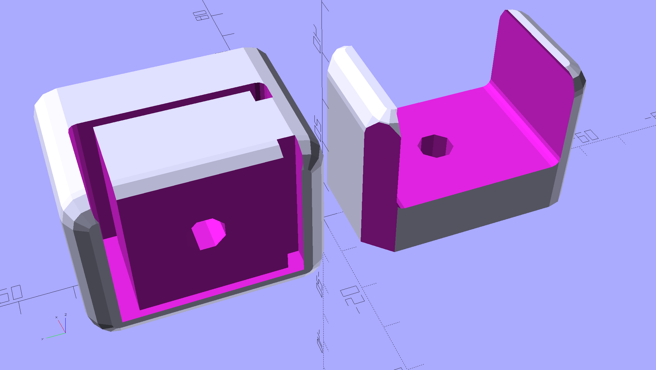
    Those are all early versions of the mounting blocks, because this happened while printing the final set:

    MPCNC - failed bar clamp mounts
    MPCNC – failed bar clamp mounts

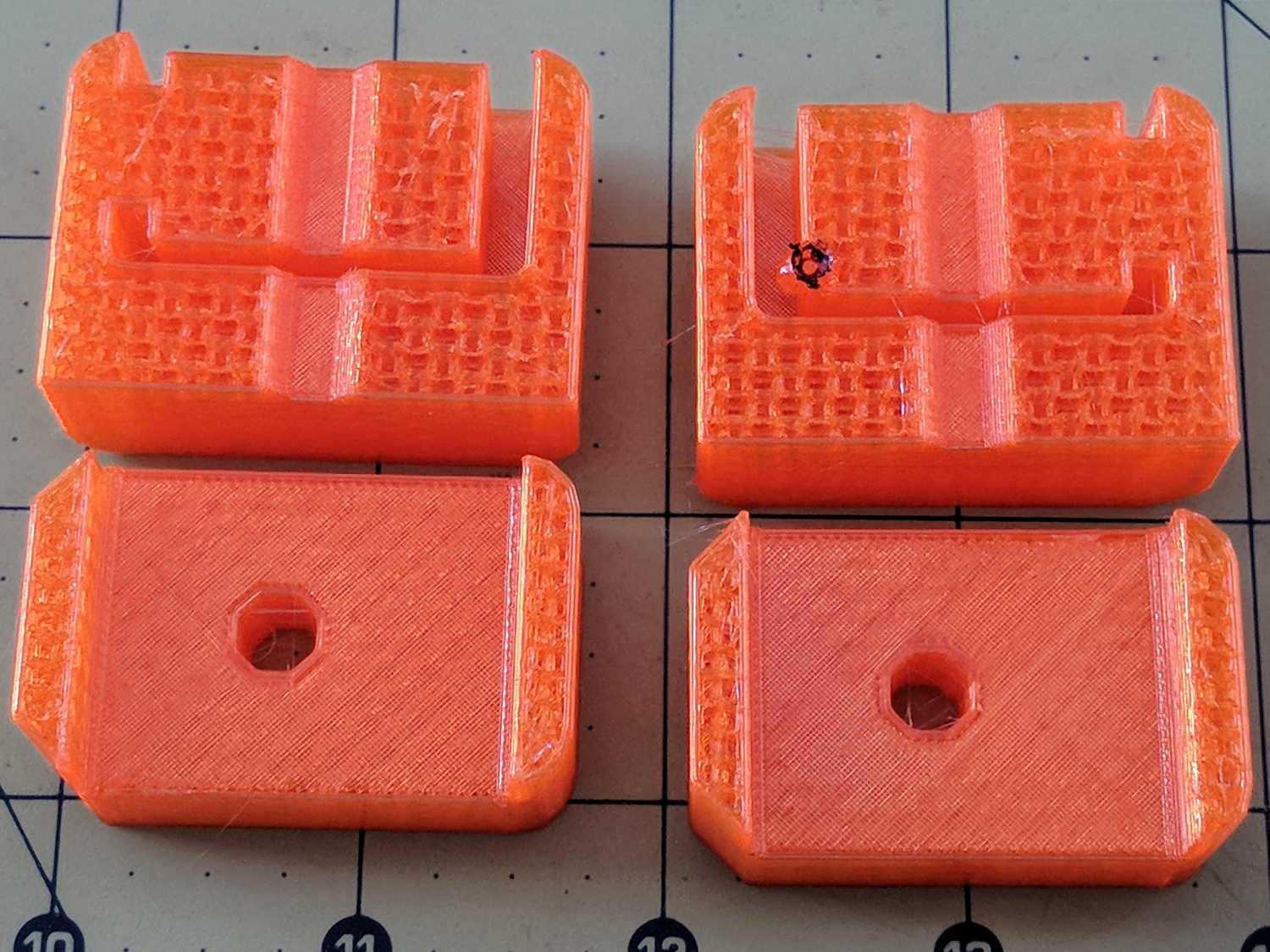
    The black smudge on the block in the upper right is what happens when a MAXTEMP error shuts the printer down in mid-stride, leaving the nozzle to cool in the part. Looks like it’s time for a new thermistor …

  • MPCNC: Bar Clamp Mounts

    Rather than attach a spoil board directly to the bench top under the MPCNC, one can grab it in bar clamps anchored to the bench, which requires suitable mounts. Because bar clamps are all the same, one must be flipped over to point the other way, soooo the mounts come in mirror-image sets.

    Holding the clamp on the left side of the table:

    Bar Clamp Mounts - Left - solid model
    Bar Clamp Mounts – Left – solid model

    For the right-side clamp:

    Bar Clamp Mounts - Right - solid model
    Bar Clamp Mounts – Right – solid model

    The chunky clamp prints on its end, with its bottom surface facing away from you, to let the block in the middle print without support. In that orientation, the bar slides in from the top.

    The fancy rounded corners happened while I iterated on getting the dimensions right.

    Actually printing and installing the things turned out to be separate challenges.

    The OpenSCAD source code as a GitHub Gist:

    // MPCNC Bar Clamp Mounts
    // Ed Nisley KE4ZNU – 2018-02-03
    Layout = "Build"; // BarEnd EndBlock ScrewBlock Build
    Chirality = "Right"; // bar handedness = side with opening
    /* [Extrusion] */
    ThreadThick = 0.25; // [0.20, 0.25]
    ThreadWidth = 0.40; // [0.40]
    /* [Hidden] */
    Protrusion = 0.1; // [0.01, 0.1]
    HoleWindage = 0.2;
    function IntegerMultiple(Size,Unit) = Unit * ceil(Size / Unit);
    ID = 0;
    OD = 1;
    LENGTH = 2;
    //- Adjust hole diameter to make the size come out right
    module PolyCyl(Dia,Height,ForceSides=0) { // based on nophead's polyholes
    Sides = (ForceSides != 0) ? ForceSides : (ceil(Dia) + 2);
    FixDia = Dia / cos(180/Sides);
    cylinder(r=(FixDia + HoleWindage)/2,h=Height,$fn=Sides);
    }
    /* [Clamp] */
    BarEndOut = [34.5,21.0]; // outside dimensions
    BarEndIn = [28.0,18.0]; // … inside
    BarEndSlot = [2.8,11.5]; // slot on open side
    BarEndRadius = 1.5; // corner rounding
    NumSides = 3*4; // … and sides
    BarHeightOC = 22.0; // min height above bench
    Clearance = 0.2; // overall bar clearance
    PinOffset = [14.0,2.5]; // clamp hardware pin location
    PinOD = 6.5; // … pin OD
    WallThick = 5.0; // basic wall & floor thickness
    EndBlockSize = [2*PinOffset.x + WallThick,BarEndOut.x + 2*WallThick,BarHeightOC + BarEndOut.y/2];
    ScrewBlockSize = [2*PinOffset.x,BarEndOut.x + 2*WallThick,BarHeightOC + BarEndOut.y/2];
    //—–
    // Define shapes
    // Aluminum bar extrusion
    module BarEnd(Length = 2.0,Hollow=true) {
    linear_extrude(height=Length,convexity=3)
    offset(delta=Clearance)
    difference() {
    hull()
    for (i=[-1,1], j=[-1,1])
    translate([i*(BarEndOut.x/2 – BarEndRadius),j*(BarEndOut.y/2 – BarEndRadius)])
    circle(r=BarEndRadius,$fn=3*4); // not related to block corner rounding
    if (Hollow) {
    translate([BarEndOut.x/2 – BarEndIn.x/2 – BarEndSlot.x,0])
    square(BarEndIn,center=true);
    translate([BarEndOut.x/2,0])
    square([BarEndOut.x,BarEndSlot.y],center=true);
    }
    }
    }
    // Block supporting open end of Bar
    module EndBlock() {
    Normal = (Chirality == "Left") ? [0,0,0] : [0,1,0];
    Radius = WallThick;
    mirror(Normal)
    difference() {
    if (true)
    hull() {
    dx = EndBlockSize.x/2 – Radius;
    dy = EndBlockSize.y/2 – Radius;
    for (i=[-1,1],j=[-1,1])
    translate([i*dx,j*dy,EndBlockSize.z – Radius]) {
    sphere(r=Radius,$fn=NumSides);
    cylinder(r=Radius,h=Protrusion,$fn=NumSides);
    }
    for (i=[-1,1],j=[-1,1])
    translate([i*dx,j*dy,0])
    cylinder(r=Radius,h=Protrusion,$fn=NumSides);
    }
    else
    translate([-EndBlockSize.x/2,-EndBlockSize.y/2,0])
    cube(EndBlockSize,center=false);
    translate([EndBlockSize.x/2 – PinOffset.x,0*PinOffset.y,-Protrusion])
    rotate(180/8)
    PolyCyl(PinOD,2*EndBlockSize.z,8);
    translate([EndBlockSize.x/2 – 2*PinOffset.x,0,BarHeightOC])
    rotate([0,90,0]) rotate(-90)
    BarEnd(Length=EndBlockSize.x);
    }
    }
    // Block supporting screw end of Bar
    // Ad-hoc chamfers to clear screw mount castings
    module ScrewBlock() {
    Normal = (Chirality == "Left") ? [0,0,0] : [0,1,0];
    Radius = WallThick;
    mirror(Normal)
    difference() {
    if (true)
    hull() {
    dx = ScrewBlockSize.x/2 – Radius;
    dy = ScrewBlockSize.y/2 – Radius;
    for (i=[-1,1],j=[-1,1])
    translate([i*dx,j*dy,ScrewBlockSize.z – Radius]) {
    sphere(r=Radius,$fn=NumSides);
    cylinder(r=Radius,h=Protrusion,$fn=NumSides);
    }
    for (i=[-1,1],j=[-1,1])
    translate([i*dx,j*dy,0])
    cylinder(r=Radius,h=Protrusion,$fn=NumSides);
    }
    else
    translate([0,0,ScrewBlockSize.z/2])
    cube(ScrewBlockSize,center=true);
    translate([0,PinOffset.y,-Protrusion])
    rotate(180/8)
    PolyCyl(PinOD,2*ScrewBlockSize.z,8);
    translate([-ScrewBlockSize.x/2 – Protrusion,0,BarHeightOC])
    rotate([0,90,0]) rotate(-90)
    BarEnd(Length=ScrewBlockSize.x + 2*Protrusion,Hollow=false);
    for (i=[-1,1])
    translate([i*ScrewBlockSize.x/2,ScrewBlockSize.y/2,ScrewBlockSize.z – Protrusion])
    rotate(45)
    cube([sqrt(2)*WallThick,sqrt(2)*WallThick,2*ScrewBlockSize.z],center=true);
    }
    }
    //—–
    // Build things
    if (Layout == "BarEnd")
    BarEnd();
    if (Layout == "EndBlock")
    EndBlock();
    if (Layout == "ScrewBlock")
    ScrewBlock();
    if (Layout == "Build") {
    translate([EndBlockSize.z/2,0.6*EndBlockSize.y,EndBlockSize.x/2])
    rotate([0,-90,0])
    EndBlock();
    translate([0,-0.6*ScrewBlockSize.y,0])
    ScrewBlock();
    }

    The original doodles, with initial dimensions & some bad ideas:

    Bar Clamp Mount - Dimension Doodles
    Bar Clamp Mount – Dimension Doodles


  • Juki TL-2010Q Sewing Machine: Thread Guide

    It turns out the thread guide on Mary’s new Juki TL-2010Q sewing machine has what’s euphemistcally known as “negative clearance” with the ruler foot she uses for quilting patterns. With the foot raised to move the cloth, inadvertently pressing the foot pedal or turning the handwheel can crunch the thread guide against the foot.

    As you might expect, the intricately bent wire thread guide doesn’t survive the encounter. Not having a spare ready to hand and not knowing quite what it should look like, I reshaped it as best I could:

    Juki thread guide - in vise
    Juki thread guide – in vise

    It worked moderately well:

    Juki thread guide - reshaped installed
    Juki thread guide – reshaped installed

    The automatic needle threader wasn’t reliable, but she could cope until the replacements arrived.

    Comparing the new one (left) with the wrecked one (right) shows I didn’t re-bend the loop tightly enough, putting the end on the right at the wrong angle:

    Juki thread guide - new vs reshaped
    Juki thread guide – new vs reshaped

    It’s the kind of shape you can duplicate by the thousands with a production machine, but can’t make at home without entirely too much tedious effort.

    The new one works fine, seen here in front of a walking foot, with the auto-threader looming in the upper foreground:

    Juki thread guide - new installed
    Juki thread guide – new installed

    Aaaand now we have spares!

  • Lathe-Turned Drugs

    For reasons not relevant here, I had to wake up a New Old Stock bottle of an eye drug dispensed as a suspension in a small bottle:

    Lathe turned drugs
    Lathe turned drugs

    A few hours at 50 RPM and it’s all shook up.

  • MPCNC: Stepper Drive vs. Back EMF at the Edge of Madness

    This is what the stepper current looks like when you run an MPCNC at 12000 mm/min = 200 mm/s from a 24 V supply:

    G0 X 25.6 - A drive - 200 mm-s - low I - 24V 200mA-div
    G0 X 25.6 – A drive – 200 mm-s – low I – 24V 200mA-div

    The vertical scale for the winding current in the top trace is 200 mA/div, so those flat sections run about 150 mA, well under the 600 mA peak found at lower speeds. This G0 move ramps up to 12000 mm/min and shows the current falling off and the sine wave deteriorating:

    G0 X 200 mm-s - 24V 200mA-div
    G0 X 200 mm-s – 24V 200mA-div

    The motor turns at 375 RPM, which means each stepper generates 12 Vpk back EMF, so the A4988 driver has absolutely no control authority near what should be the zero crossings of the current waveform.

    The taller waveform along the bottom of the first scope shot comes from the H bridge output tending to increase the current waveform, so it’s applying a solid +24  during the flat top section and not only gets no traction, but actually loses ground just after the middle of the screen. Eventually the back EMF drops and the current begins increasing, but long after what should be the 600 mA peak current where the driver flips the H bridge and begins trying to decrease the current.

    Here’s a detailed view of the section just after the left cursor:

    G0 X 25.6 - A drive - low I - detail - 24V 200mA-div
    G0 X 25.6 – A drive – low I – detail – 24V 200mA-div

    The step pulses tick along at 50 μs intervals, with only two driver PWM pulses for each one.

    A 2-flute carbide cutter spinning at 20000 RPM with a 0.25 mm chip load calls for a speed of 10000 mm/min. Alas, the stock 12 V supply stalls at 8000 mm/min:

    MPCNC G1X20F8000 - 500 mA-div 50 ms-div
    MPCNC G1X20F8000 – 500 mA-div 50 ms-div

    It’s facing something over 9 V of back EMF from the motors at that speed. The chaotic spikes near the middle of the current waveform show where the rotor dropped out of lock with the driver and begins shoving the current around.

    So that’s why you really can’t use a 12 V power supply with series stepper motors, at least if you want to run ’em at more than moderate speeds. It’s not at all clear the 24 V supply will provide enough motor torque to run at 10 k mm/min, so I gotta wrap an enclosure around the electronics and start making some chips to see how it behaves …

  • Monthly Science: Wearable LED vs. Dead CR2032 Lithium Cell

    Eight months later, the dead CR2032 cell driving the “ruby” wearable LED has dropped to 2.15 V:

    Wearable LED - on window
    Wearable LED – on window

    It’s not a true red LED with a 1.5-ish V forward drop, but a white / blue LED with red phosphor or a red filter, with a forward drop well over 3 V.

    Against the sunlit backdrop from our kitchen window, the LED looks dark:

    Wearable LED - daylight
    Wearable LED – daylight

    Seen in a dim room, it’s still glowing:

    Wearable LED - dim light
    Wearable LED – dim light

    The current is now far below the 1 mA/div of my Tek A6302 Hall effect probe, so I have no way to measure the few microamps lighting the junction.

    The coarse grid outside the window is a swatch of deer netting we put up during feeder season to keep the birds from killing themselves on the glass.

  • VFAT Time Zone Offset Correction

    An SJCAM M20 action camera includes the date and time in its file names, but the directory entries appear with the wrong timestamp:

    sudo mount -o uid=ed /dev/sdc1 /mnt/part
    ll -tr /mnt/part/DCIM/Photo/ | head
    total 4.8G
    drwxr-xr-x 4 ed root  16K Apr  8  2016 ../
    drwxr-xr-x 2 ed root 144K Jan 25 18:52 ./
    -rwxr-xr-x 1 ed root 3.8M Jan 26 05:08 2018_0126_100825_001.JPG*
    -rwxr-xr-x 1 ed root 3.8M Jan 26 05:08 2018_0126_100830_002.JPG*
    

    I’m in the Eastern US time zone, -5 hr from UTC.

    By definition, FAT directory entries contain the “local time” when the file was created / changed. Because it cannot know which “local time” applies, the Linux VFAT filesystem treats the timestamp as UTC and adjusts it by -5 hr.

    So the camera writes the directory timestamps properly. When mounted, Linux correctly (for a reasonable definition of correctly) regards them as UTC, knocks off five hours to match this time zone, and displays the result.

    Alas, disabling the VFAT timestamp conversion has no effect:

    sudo mount -o uid=ed,tz=UTC /dev/sdc1 /mnt/part
    ll -tr /mnt/part/DCIM/Photo/ | head
    total 4.8G
    drwxr-xr-x 4 ed root  16K Apr  8  2016 ../
    drwxr-xr-x 2 ed root 144K Jan 25 18:52 ./
    -rwxr-xr-x 1 ed root 3.8M Jan 26 05:08 2018_0126_100825_001.JPG*
    -rwxr-xr-x 1 ed root 3.8M Jan 26 05:08 2018_0126_100830_002.JPG*
    

    I’m not sure why that doesn’t do anything; it doesn’t generate any error messages.

    Although it seems like a reasonable thing, one cannot force a specific time zone with, say, tz=EST or tz=EDT or tz=UTC8 or whatever.

    You can specify an offset in minutes:

    sudo mount -o uid=ed,time_offset=$((-5*60)) /dev/sdc1 /mnt/part
    ll -tr /mnt/part/DCIM/Photo/ | head
    total 4.8G
    drwxr-xr-x 4 ed root  16K Apr  8  2016 ../
    drwxr-xr-x 2 ed root 144K Jan 25 23:52 ./
    -rwxr-xr-x 1 ed root 3.8M Jan 26 10:08 2018_0126_100825_001.JPG*
    -rwxr-xr-x 1 ed root 3.8M Jan 26 10:08 2018_0126_100830_002.JPG*
    

    The time_offset value is subtracted from the directory timestamp, which means you’re feeding in the actual time offset from UTC, including whatever Daylight Saving Time offset may be in order.

    So Linux takes the FAT timestamp, adds (subtracts a negative) 5 hr, and displays the result as my (now correct) local time.

    I suppose I could set the camera to UTC, but then the camera’s on-screen and in-video timestamps would be off by four or five hours, depending on the season. So it goes.