The Smell of Molten Projects in the Morning

Ed Nisley's Blog: Shop notes, electronics, firmware, machinery, 3D printing, laser cuttery, and curiosities. Contents: 100% human thinking, 0% AI slop.

Author: Ed

  • USB Testers vs. Reality

    USB Testers vs. Reality

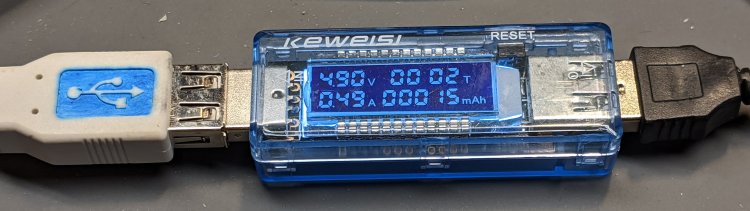
    Set up a test harness with a USB tester between two amputated USB cables:

    USB Testers - Keweisi plugged
    USB Testers – Keweisi plugged

    Input comes from a bench power supply:

    USB Testers - 5 V input clips
    USB Testers – 5 V input clips

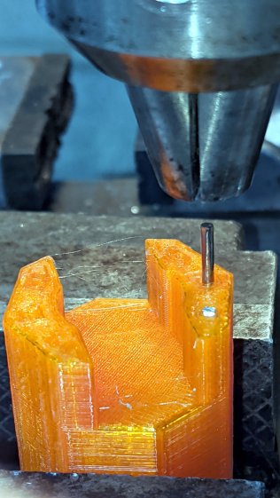
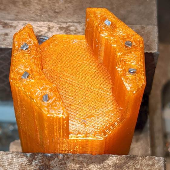
    Output goes to an 8 Ω power resistor:

    USB Testers - 8 ohm load
    USB Testers – 8 ohm load

    Yes, it’s mounted on the isothermal block from back in the Thing-O-Matic days, disspating barely 2 W. Thermocouples FTW, but in this case I don’t care about the temperature.

    Because these are random USB cables, they come with the usual caveats. Indeed, I measured a 9.8 Ω loop resistance (!) at the input end. The resistor is slightly under 8Ω, so the 1.8 Ω wire resistance suggests (at least) one of the USB cables contains very little copper. That’s measured without the USB tester in series, because it tries really hard to power up from the ohmmeter’s source voltage and basically shorts out the resistor.

    Both testers accurately report the source voltage with no load, so I presume the voltage shown with current flowing through the resistor represents the actual voltage at the tester. The source cable drops a substantial voltage under load.

    The 8 Ω resistor should draw 5 V / 8 Ω = 625 mA at 5 V. The voltmeter probes provide a non-intrusive way to measure the actual current by working backwards: current = volts / 8 Ω. As it turned out, the resistor sees less than 4 V with the bench supply set to 5.0 V.

    So, we begin.

    With the bench supply at 5.5 V, the Keweisi meter shows 4.9 V and 0.48 A with 4.0 V across the resistor for an actual 500 mA current. The source cable drops 600 mV, indicating a wire resistance of 1.2 Ω, about 2/3 of the total wire resistance.

    The anonymous meter produces two different results for an actual 500 mA current, depending on nothing under my control:

    • Supply 5.3 V, indicated 5.0 V and 0.5 A
    • Supply 5.1 V, indicated 4.76 V and 0.5 A

    Both results show about 300 mV source drop, half of the Keweisi meter’s 600 mV, suggesting a wire resistance of 0.6 Ω. The meter displays a blinking ▲, presumably indicating the input voltage is kinda high.

    I have no explanation.

    After the meters measured an actual 500 mA load for about an hour:

    • Keweisi: 1.6 hr → 782 mA·h, should be 800 mA·h
    • Anonymous: 1.0 hr → 515 mA·h, should be 500 mA·h

    Which roughly agrees with the battery charge data:

    USB Testers - Charge vs Runtime
    USB Testers – Charge vs Runtime

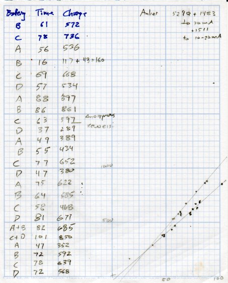
    The anonymous meter seems reasonably accurate, the Keweisi meter undershoots by 2.5%, and they’re both Close Enough for simple measurements.

    There’s probably a duty cycle effect, too, because the battery charger presents a pulsed load, but I’m just not going to worry about it.

  • Robin Nest: Eggs!

    Robin Nest: Eggs!

    After pausing to recover from construction, Ms Robin laid four eggs in four days:

    • Garage Robin Nest - first egg - 2020-05-28
    • Garage Robin Nest - 2 eggs - 2020-05-29
    • Garage Robin Nest - 3 eggs - 2020-05-30
    • Garage Robin Nest - 4 eggs - 2020-05-31

    She’s surprisingly tolerant of our comings and goings, as well as garage door openings and closings:

    Garage Robin Nest - robin brooding
    Garage Robin Nest – robin brooding

    We’re trying to stay out of her way as much as possible.

    The gallery pix come from my phone, held against the soffit over the nest, and aimed entirely by feel, while standing on the Greater Ladder. If I had access to the top of the soffit, I’d drill a webcam hole, but …

  • Tree Stump Removal

    Tree Stump Removal

    This makes writing 3D modeling code and turning threads look downright attractive:

    Tree stump - crater
    Tree stump – crater

    The previous owners apparently surrounded a cedar (?) tree with a ring of large, decorative rocks. The tree vanished long before we arrived, with the stump accreting random stones, bricks, and similar impedimenta ever since; my first task involved (re)moving a couple hundred pounds of rocky debris.

    After using the stump as a fulcrum for that steel bar to break the rotted roots and loosen the surrounding soil, it’s out and away:

    Tree stump - excavated
    Tree stump – excavated

    Back to the Basement Laboratory …

  • Screw Thread Measurement

    Screw Thread Measurement

    While I was cutting threads for the Floor Lamp poles, I tried measuring my progress over wires:

    Floor Lamp - tube fitting - thread measurement
    Floor Lamp – tube fitting – thread measurement

    Those are three lengths of music wire, slightly bent from their storage roll, held in place with a precision clamp metric micrometer. Given the crudity of the setup, the uncalibrated wire diameter, and my lack of thread-fu, the results came out both close and unconvincing.

    A set of real thread measuring wires being cheap & readily available, I’m prepared for the next time around this block:

    Thread Measuring Wires - eBay set
    Thread Measuring Wires – eBay set

    The 185 mil “wires” (they’re all allegedly ground rod) will let me cut threads matching things like a Jesus nut; they’re suited for 3 TPI / 8 mm pitch screws. Mostly, wires from the front row will be all I ever need.

    Which look like this in action:

    Thread Measuring Wires - eBay setThread Measuring Wires - detail
    Thread Measuring Wires – eBay setThread Measuring Wires – detail

    The black doodad (the set includes half a dozen for all the wire sizes) fits over the micrometer anvil and holds two wires betwixt anvil and screw, leaving me to manipulate the screw, the third wire, and the micrometer with my remaining hands. Hence the vise holding the micrometer, which is known to be Very Bad Practice.

    From the side:

    Thread Measuring Wires - overview
    Thread Measuring Wires – overview

    All of the smaller wires measure 0.5 mil too thin, which is likely due to my lack of calibrated measurement equipment:

    Thread Measuring Wires - scant 24 mil
    Thread Measuring Wires – scant 24 mil

    The few thread pitch diameters I measured also came out slightly too small, again likely due to calibration and screw tolerances.

    The LittleMachineShop description of measuring threads over wires seems entirely adequate.

    To forestall link rot, a slightly rearranged version of their tables of wire constants:

    Thread Wire Measurement Constants
    Thread Wire Measurement Constants

    The lower table has metric thread pitches with the wire sizes in inches.

    You measure the distance over the recommended wire (in inches or millimeters, as appropriate), subtract the constant, and get the pitch diameter in the same units. Conversely, add the constant to the desired pitch diameter to get the target over-wire distance, carefully cut the thread until it measures a bit less than that, back up sixty seconds, and cut it spot on.

    Verily, it is written: there is no UnDo key (⎌) in machine shop work.

  • More WS2812 Failures

    More WS2812 Failures

    Even though I’m using what seem to be good-quality parts, one of the WS2812 RGB LEDs in a Glass Tile frame died:

    Glass Tile - 2x2 - first WS2812B failure
    Glass Tile – 2×2 – first WS2812B failure

    It passed the Josh Sharpie Test:

    Glass Tile - WS2812 failure - PCB unknown
    Glass Tile – WS2812 failure – PCB unknown

    After building the third Glass Tile unit, one of the LEDs didn’t light up due to an easily diagnosed problem:

    Glass Tile - WS2812 failure - PCB cold solder - as found
    Glass Tile – WS2812 failure – PCB cold solder – as found

    A closer look:

    Glass Tile - WS2812 failure - PCB cold solder
    Glass Tile – WS2812 failure – PCB cold solder

    Shortly thereafter, the Nissan Fog Lamp developed an obvious beam problem:

    Nissan Fog Lamp - failed WS2812 effect
    Nissan Fog Lamp – failed WS2812 effect

    The WS2812 had the proper voltages / signals at all its pins and was still firmly stuck to the central “heatsink”:

    Nissan Fog Lamp - failed WS2812 detail
    Nissan Fog Lamp – failed WS2812 detail

    It also passed the Josh Sharpie Test:

    Glass Tile - WS2812 failure - tape - unknown
    Glass Tile – WS2812 failure – tape – unknown

    I’m particularly surprised by this one, because eleven of the twelve flex-PCB WS2812s in the Hard Drive Platter light have been running continuously for years with no additional failures.

    The alert reader will note the common factor: no matter what substrate the LED is (supposed to be) soldered to, no matter when I bought it, no matter what it’s wired into, a WS2812 will fail.

    They’re all back in operation:

    Glowing Algorithmic Art
    Glowing Algorithmic Art

    Although nobody knows for how long …

    Obviously, it’s time to refresh my programmable RGB LED stockpile!

  • PiHole with DNS-over-HTTP: Revised

    More than a year later, the PiHole continues to work fine, but the process for installing the Cloudflare DoH machinery has evolved.

    (And, yes, it’s supposed to be DNS-over-HTTPS. So it goes.)

    To forestall link rot, the key points:

    cd /tmp ;  wget https://bin.equinox.io/c/VdrWdbjqyF/cloudflared-stable-linux-arm.tgz
    tar -xvzf cloudflared-stable-linux-arm.tgz 
    sudo cp cloudflared /usr/local/bin
    sudo chmod +x /usr/local/bin/cloudflared
    sudo cloudflared -v
    sudo useradd -s /usr/sbin/nologin -r -M cloudflared
    sudo nano /etc/default/cloudflared
    ----
    CLOUDFLARED_OPTS=--port 5053 --upstream https://1.1.1.1/dns-query --upstream https://1.0.0.1/dns-query 
    ----
    sudo chown cloudflared:cloudflared /etc/default/cloudflared
    sudo chown cloudflared:cloudflared /usr/local/bin/cloudflared
    sudo nano /etc/systemd/system/cloudflared.service
    ----
    [Unit]
    Description=cloudflared DNS over HTTPS proxy
    After=syslog.target network-online.target
    
    [Service]
    Type=simple
    User=cloudflared
    EnvironmentFile=/etc/default/cloudflared
    ExecStart=/usr/local/bin/cloudflared proxy-dns $CLOUDFLARED_OPTS
    Restart=on-failure
    RestartSec=10
    KillMode=process
    
    [Install]
    WantedBy=multi-user.target
    ----
    sudo systemctl enable cloudflared
    sudo systemctl start cloudflared
    sudo systemctl status cloudflared

    Then aim PiHole’s DNS at 127.0.0.1#5053. It used to be on port #54, for whatever that’s worth.

    Verify it at https://1.1.1.1/help, which should tell you DoH is in full effect.

    To update the daemon, which I probably won’t remember:

    wget https://bin.equinox.io/c/VdrWdbjqyF/cloudflared-stable-linux-arm.tgz
    tar -xvzf cloudflared-stable-linux-arm.tgz
    sudo systemctl stop cloudflared
    sudo cp ./cloudflared /usr/local/bin
    sudo chmod +x /usr/local/bin/cloudflared
    sudo systemctl start cloudflared
    cloudflared -v
    sudo systemctl status cloudflared

    And then It Just Works … again!

  • Garden Hose Valve Wrench: Reinforced

    Garden Hose Valve Wrench: Reinforced

    After five gardening seasons, my simple 3D printed wrench broke:

    Hose Valve Knob - fractured
    Hose Valve Knob – fractured

    Although Jason’s comment suggesting carbon-fiber reinforcing rods didn’t prompt me to lay in a stock, ordinary music wire should serve the same purpose:

    Hose Valve Knob - cut pins
    Hose Valve Knob – cut pins

    The pins are 1.6 mm diameter and 20 mm long, chopped off with hardened diagonal cutters. Next time, I must (remember to) grind the ends flat.

    The solid model needs holes in appropriate spots:

    Hose Valve Knob - Reinforced - Slic3r
    Hose Valve Knob – Reinforced – Slic3r

    Yes, I’m going to put round pins in square holes, without drilling the holes to the proper diameter: no epoxy, no adhesive, just 20 mm of pure friction.

    The drill press aligns the pins:

    Hose Valve Knob - pin ready
    Hose Valve Knob – pin ready

    And rams them about halfway down:

    Hose Valve Knob - pin midway
    Hose Valve Knob – pin midway

    Close the chuck jaws and shove them flush with the surface:

    Hose Valve Knob - pins installed
    Hose Valve Knob – pins installed

    You can see the pins and their solid plastic shells through the wrench stem:

    Hose Valve Knob - assembled
    Hose Valve Knob – assembled

    Early testing shows the reinforced wrench works just as well as the previous version, even on some new valves sporting different handles, with an equally sloppy fit for all. No surprise: I just poked holes in the existing model and left all the other dimensions alone.

    The OpenSCAD source code as a GitHub Gist:

    // Hose connector knob
    // Ed Nisley KE4ZNU – June 2015
    // 2020-05 add reinforcing rods
    Layout = "Build"; // [Knob, Stem, Show, Build]
    RodHoles = true;
    //- Extrusion parameters – must match reality!
    /* [Hidden] */
    ThreadThick = 0.25;
    ThreadWidth = 0.40;
    function IntegerMultiple(Size,Unit) = Unit * ceil(Size / Unit);
    Protrusion = 0.1;
    HoleWindage = 0.2;
    //——
    // Dimensions
    /* [Dimensions] */
    RodOD = 1.6;
    RodAngle = 35;
    /* [Hidden] */
    StemOD = 30.0; // max OD for valve-to-valve clearance
    BossOD = 16.0; // single-ended handle boss
    SlotWidth = 13.0;
    SlotHeight = 10.0;
    StemInset = 10.0;
    StemLength = StemInset + SlotHeight + 25.0;
    StemSides = 2*4;
    Align = 0*180/StemSides; // 1* produces thinner jaw ends
    KnobOD1 = 70; // maximum dia without chamfer
    KnobOD2 = 60; // top dia
    KnobSides = 4*4;
    DomeHeight = 12; // dome shape above lobes
    KnobHeight = DomeHeight + 2*SlotHeight;
    DomeOD = KnobOD2 + (KnobOD1 – KnobOD2)*(DomeHeight/KnobHeight);
    DomeArcRad = (pow(KnobHeight,2) + pow(DomeOD,2)/4) / (2*DomeHeight);
    RodBCD = (StemOD + BossOD)/2;
    //- Adjust hole diameter to make the size come out right
    module PolyCyl(Dia,Height,ForceSides=0) { // based on nophead's polyholes
    Sides = (ForceSides != 0) ? ForceSides : (ceil(Dia) + 2);
    FixDia = Dia / cos(180/Sides);
    cylinder(r=(FixDia + HoleWindage)/2,h=Height,$fn=Sides);
    }
    //– Stem for valve handles
    module Stem() {
    difference() {
    rotate(Align)
    cylinder(d=StemOD,h=StemLength,$fn=StemSides);
    translate([0,0,SlotHeight/2 – Protrusion/2])
    cube([2*StemOD,SlotWidth,(SlotHeight + Protrusion)],center=true);
    translate([0,0,-Protrusion])
    cylinder(d=BossOD,h=SlotHeight,$fn=2*StemSides);
    if (RodHoles)
    for (i=[-1:1])
    rotate(i*RodAngle + 90)
    for (j=[-1,1])
    translate([j*RodBCD/2,0,-Protrusion])
    rotate(180/4)
    PolyCyl(RodOD,2*SlotHeight,4);
    }
    }
    //– Hand-friendly knob
    module KnobCap() {
    difference() {
    scale([1.0,0.75,1.0])
    rotate(180/KnobSides)
    intersection() {
    translate([0,0,(KnobHeight-DomeArcRad)])
    sphere(r=DomeArcRad,$fa=180/KnobSides);
    cylinder(r1=KnobOD1/2,r2=KnobOD2/2,h=KnobHeight,$fn=KnobSides);
    cylinder(r1=KnobOD2/2,r2=KnobOD1/2,h=KnobHeight,$fn=KnobSides);
    }
    translate([0,0,-Protrusion])
    rotate(Align)
    cylinder(d=(StemOD + 2*ThreadWidth),h=(StemInset + Protrusion),$fn=StemSides);
    }
    }
    //- Build it
    if (Layout == "Knob")
    KnobCap();
    if (Layout == "Stem")
    Stem();
    if (Layout == "Build") {
    translate([-KnobOD1/2,0,0])
    KnobCap();
    translate([StemOD/2,0,StemLength])
    rotate([180,0,0])
    Stem();
    }
    if (Layout == "Show") {
    translate([0,0,0])
    Stem();
    translate([0,0,StemLength – StemInset])
    KnobCap();
    }