The Smell of Molten Projects in the Morning

Ed Nisley's Blog: Shop notes, electronics, firmware, machinery, 3D printing, laser cuttery, and curiosities. Contents: 100% human thinking, 0% AI slop.

Author: Ed

  • Monthly Science: Small Praying Mantis

    Monthly Science: Small Praying Mantis

    These Praying Mantis nymphs may have emerged from the ootheca I rescued from the grass trimming operation earlier this year:

    Praying Mantises in grass - 2020-07-24
    Praying Mantises in grass – 2020-07-24

    The closest one was about 60 mm long, with plenty of growing ahead in the next few months:

    Praying Mantis - 2020-07-24
    Praying Mantis – 2020-07-24

    A few days later, I spotted a smaller one, maybe 40 mm from eyes to cerci, hiding much deeper in the decorative grass clump. Given their overall ferocity, it was likely hiding from its larger sibs.

    They have also been stilting their way across the window glass and screens in search of better hunting grounds. My affixing their oothecae to another bush may have disoriented them at first, but they definitely know where their next meal comes from!

    Perhaps as a bonus, a Katydid appeared inside the garage, stuck to the side of a trash can that Came With The House™ long ago:

    Katydid
    Katydid

    I deported it outside, in hopes of increasing the world’s net happiness.

    The stickers covering the can say “WPDH: A Decade of Rock ‘n’ Roll”, suggesting they date back to 1986, ten years after (Wikipedia tells me) WPDH switched from country to rock. Neither genre did much for me, so I never noticed.

  • Reinforced QD Propane Adapter Tool

    Reinforced QD Propane Adapter Tool

    Having just emptied a propane tank while making bacon, I couldn’t find any of the wrench adapters I made to remove the QD adapter from the tank’s POL fitting. With memory of the broken garden valve wrench still fresh, I tweaked the solid model to include a trio of 1 mm music wire reinforcements:

    Propane QD Adapter Tool - reinforced - Slic3r
    Propane QD Adapter Tool – reinforced – Slic3r

    Holes that small require clearing with a 1 mm drill, after which ramming the wires in place poses no problem:

    Reinforced QD Adapter Tool - inserting wire
    Reinforced QD Adapter Tool – inserting wire

    Except for the one that got away:

    Reinforced QD Adapter Tool - errant wire
    Reinforced QD Adapter Tool – errant wire

    The music wire came from a coil and each snippet required gentle straightening; perhaps that one wasn’t sufficiently bar-straight.

    Anyhow, I printed two tools for that very reason:

    Reinforced QD Adapter Tool - side view
    Reinforced QD Adapter Tool – side view

    They’re now where I can’t miss ’em the next time I need them, although that’s not where the previous ones reside.

    The OpenSCAD source code as a GitHub Gist:

    // Propane tank QD connector adapter tool
    // Ed Nisley KE4ZNU November 2012
    // 2018-04-08 toss MCAD includes overboard
    // 2020-07-27 add reinforcing rods
    //- Extrusion parameters must match reality!
    // Print with about half a dozen perimeter threads and 50% infill
    ThreadThick = 0.25;
    ThreadWidth = 2.0 * ThreadThick;
    HoleWindage = 0.2;
    function IntegerMultiple(Size,Unit) = Unit * ceil(Size / Unit);
    Protrusion = 0.1; // make holes end cleanly
    inch = 25.4;
    //———————-
    // Dimensions
    WrenchSize = (5/8) * inch; // across the flats
    WrenchThick = 10;
    NoseDia = 8.6;
    NoseLength = 9.0;
    LockDia = 12.5;
    LockRingLength = 1.0;
    LockTaperLength = 1.5;
    TriDia = 15.1;
    TriWide = 12.2; // from OD across center to triangle side
    TriOffset = TriWide – TriDia/2; // from center to triangle side
    TriLength = 9.8;
    NeckDia = TriDia;
    NeckLength = 4.0;
    RebarOD = 1.0; // music wire pin 1 mm = 39 mil
    RebarLength = WrenchThick + NeckLength + TriLength;
    //———————-
    // Useful routines
    module PolyCyl(Dia,Height,ForceSides=0) { // based on nophead's polyholes
    Sides = (ForceSides != 0) ? ForceSides : (ceil(Dia) + 2);
    FixDia = Dia / cos(180/Sides);
    cylinder(r=(FixDia + HoleWindage)/2,
    h=Height,
    $fn=Sides);
    }
    //——————-
    // Build it…
    $fn = 4*6;
    union() {
    translate([0,0,(WrenchThick + NeckLength + TriLength – LockTaperLength – LockRingLength + Protrusion)])
    cylinder(r1=NoseDia/2,r2=LockDia/2,h=LockTaperLength);
    translate([0,0,(WrenchThick + NeckLength + TriLength – LockRingLength)])
    cylinder(r=LockDia/2,h=LockRingLength);
    difference() {
    union() {
    translate([0,0,WrenchThick/2])
    cube([WrenchSize,WrenchSize,WrenchThick],center=true);
    cylinder(r=TriDia/2,h=(WrenchThick + NeckLength +TriLength));
    cylinder(r=NoseDia/2,h=(WrenchThick + NeckLength + TriLength + NoseLength));
    }
    for (a=[-1:1]) {
    rotate(a*120)
    translate([(TriOffset + WrenchSize/2),0,(WrenchThick + NeckLength + TriLength/2 + Protrusion/2)])
    cube([WrenchSize,WrenchSize,(TriLength + Protrusion)],center=true);
    }
    for (a=[-1:1]) {
    rotate(a*120 + 60)
    translate([NoseDia/2,0,-Protrusion])
    PolyCyl(RebarOD,RebarLength,6);
    }
    }
    }

  • Half-Teaspoon Soldering

    Half-Teaspoon Soldering

    My favorite half-teaspoon measure hit the floor with a surprising sproing:

    Half-teaspoon soldering - broken
    Half-teaspoon soldering – broken

    The weld lasted far longer than anyone should own a spoon, I suppose, but it wasn’t much to begin with:

    Half-teaspoon soldering - sprung handle
    Half-teaspoon soldering – sprung handle

    Having had much the same thing happen to a measuring cup from the same set, I cleaned the back of the spoon and the front of the handle with a stainless steel wire brush in the Dremel and gingerly re-bent the handle to remove any inclination it might have to break free again:

    Half-teaspoon soldering - cleaned and rebent
    Half-teaspoon soldering – cleaned and rebent

    Some 60% silver solder (the formula evidently changed in the last few decades), nasty flux, and propane torch work produced a decent fillet:

    Half-teaspoon soldering - cooling
    Half-teaspoon soldering – cooling

    It looks a bit worse on the far side, but I’ll never tell.

    Rinse off the flux, wire-brush the joint, wash again, and it’s all good.

    I thought about excavating the resistance soldering gadget, but the torch was closer to hand and a bigger fillet seemed in order.

  • NPN RGB Astable Multivibrator Timing Adjustment

    NPN RGB Astable Multivibrator Timing Adjustment

    Back in the beginning of July, I replaced the NP-BX1 battery in the RGB Piranha astable multivibrator with a 18650 lithium cell and a USB charge controller, then watched it blink for the next two weeks on the first charge:

    Astable - 10 11 12 uF tweak - 027
    Astable – 10 11 12 uF tweak – 027

    However, the blinks looked … odd and some poking around with a Tek current probe showed the red and blue astables had locked together, so they blinked in quick succession. Alas, I don’t have a scope shot to prove it.

    I built all three astables with the same parts, figuring the normal tolerance of electrolytic caps would make the astables run at slightly different rates, which they did at first.

    This being a prototype, I just soldered a 1 µF cap onto the blue channel’s existing 10 µF cap:

    Astable - 11 uF cap - detail
    Astable – 11 uF cap – detail

    You can barely make out the top of the additional 2.2 µF cap on the red channel, through the maze of components; now, they definitely have different periods.

    Aaaand the scope shot to prove it:

    Astable NPN - 10 11 12 uF tweak - 10 mA-div
    Astable NPN – 10 11 12 uF tweak – 10 mA-div

    The bottom trace shows the battery current at 10 mA/div. The first pulse, over on the left, has the red and blue LEDs firing in quick succession with some overlap, but they separate cleanly for their next pulses.

    You don’t want to build a battery-powered astable from NPN transistors, because the 8 mA current between blinks is murderously high. In round numbers, each of the three LEDs blinks twice a second for 30 ms at 20 mA, so they average 3.6 mA, less than half the current required to keep the astables running between blinks. Over the course of 14 days, the circuit drew 11.6 mA × 336 hr = 3900 mA·h until the protection circuit shut it down.

    The lead photo shows a harvested 18650 cell, but I started with a known-good Samsung 18650 cell rated at 2600 mA·h at a 0.2C = 520 mA rate to 2.75 V. It’s comforting to see more energy trickling out at a 0.005C rate!

    I must conjure a holder with contacts for an 18650 cell, support for a trio of 2N7000 MOSFET astables, and some kind of weird spider with the RGB Piranha LED on the top. Even a harvested 18650 cell should last a couple of months with a much longer blink period (500 ms is much too fast), less LED current (this one is shatteringly bright), and a lower average current.

    And, yeah, I’ve been misspelling “Piranha” for a while.

  • Shuttles Board Game: Replacement Pegs

    Shuttles Board Game: Replacement Pegs

    For reasons not relevant here, I made replacement pegs for the Shuttles board game:

    Shuttles Game - solid model - Slic3r
    Shuttles Game – solid model – Slic3r

    Not the most challenging solid model I’ve ever conjured from the vasty digital deep, but 3D printing is really good for stuff like this.

    The OEM pegs have a hollow center, most likely to simplify stripping them from the injection mold, which I dutifully duplicated:

    Shuttles Game pegs - hollow - solid model
    Shuttles Game pegs – hollow – solid model

    It turns out the additional perimeter length inside the pegs requires 50% more printing time, far offsetting the reduced 10% infill. Given that each solid set takes just under an hour, I decided to lose half an hour of verisimilitude.

    I plunked a nice round cap atop the OEM peg’s flat end, but stopped short of printing & installing a round plug for the butt end.

    While the 3D printer’s hot, ya may as well make a bunch:

    Shuttles game pegs
    Shuttles game pegs

    Game on …

    The OpenSCAD source code as a GitHub Gist:

    Update: They’re a bit too large, so the Gist now produces tapered pegs.

    // Shuttles game pegs
    // Ed Nisley KE4ZNU – July 2020
    /* [Layout Options] */
    Layout = "Peg"; // [Build, Peg]
    Hollow = false;
    //——-
    //- Extrusion parameters must match reality!
    /* [Hidden] */
    ThreadThick = 0.25;
    ThreadWidth = 0.40;
    HoleWindage = 0.2;
    Protrusion = 0.1; // make holes end cleanly
    ID = 0;
    OD = 1;
    LENGTH = 2;
    //——-
    // Dimensions
    /* [Dimensions] */
    Peg = [4.0,7.5,26.0]; // overall length, including the rounded Cap
    Taper = 1.0;
    CapRadius = Peg[OD]/2;
    PegBaseLength = Peg[LENGTH] – CapRadius;
    NumPegs = [1,6]; // lay out in array
    ArrayCenter = [NumPegs[0] – 1,NumPegs[1] – 1] / 2;
    NumSides = 6*4;
    //——-
    module PolyCyl(Dia,Height,ForceSides=0) { // based on nophead's polyholes
    Sides = (ForceSides != 0) ? ForceSides : (ceil(Dia) + 2);
    FixDia = Dia / cos(180/Sides);
    cylinder(r=FixDia/2 + HoleWindage,h=Height,$fn=Sides);
    }
    //——-
    // One peg
    module Peg() {
    union() {
    translate([0,0,PegBaseLength])
    difference() {
    sphere(d=Peg[OD],$fn=NumSides);
    translate([0,0,-Peg[OD]/2])
    cube([2*Peg[OD],2*Peg[OD],Peg[OD]],center=true);
    }
    difference() {
    cylinder(d1=Peg[OD] – Taper,d2=Peg[OD],h=PegBaseLength,$fn=NumSides);
    if (Hollow)
    translate([0,0,-Protrusion])
    PolyCyl(Peg[ID],PegBaseLength+Protrusion,NumSides);
    }
    }
    }
    //——-
    // Build it!
    if (Layout == "Peg")
    Peg();
    if (Layout == "Build")
    for (i=[0:NumPegs[0] – 1], j=[0:NumPegs[1] – 1])
    translate([(i – ArrayCenter.x)*1.5*Peg[OD],(j – ArrayCenter.y)*1.5*Peg[OD],0])
    Peg();

  • Quilting Hexagon Template Generator

    Quilting Hexagon Template Generator

    Mary took on the task of finishing a hexagonal quilt from pieced strips, only to discover she’ll need several more strips and the myriad triangles required to turn hexagons into strips. The as-built strips do not match any of the standard pattern sizes, which meant ordinary templates were unavailing. I offered to build a template matching the (average) as-built hexagons, plus a triangle template based on those dimensions.

    Wikipedia has useful summaries of hexagon and equilateral triangle geometry and equations.

    Quilters measure hexes based on their finished side length, so a “1 inch hex” has sides measuring 1 inch, with the seam allowance extending ¼ inch beyond the sides. It’s difficult to measure finished sides with sufficient accuracy, so we averaged the side-to-side distance across several hexes.

    Some thrashing around produced a quick-and-dirty check piece that matched (most of) the stack of un-sewn hexes:

    Quilting Hexagon Cutting Template
    Quilting Hexagon Cutting Template

    That one came from a knockoff of the circle template, after some cleanup & tweakage, but failed user testing for not withstanding the side force from the rotary cutter blade. The inside and outside dimensions were correct, however, so I could proceed with some confidence I understood the geometry.

    Both the pattern width (the side-to-side distance across the inside of the hex) and the seam allowance appearing in the Customizer appear in inches, because that’s how things get measured outside the Basement Laboratory & Fabrication Facility:

    FinishedWidthInch = 2.75;
    FinishedWidth = FinishedWidthInch * inch;
    
    SeamAllowanceInch = 0.25;
    SeamAllowance = SeamAllowanceInch * inch;

    You feed in one side-to-side measurement and all other hex dimensions get calculated from that number; quilters default to a ¼ inch seam allowance. Remember, standard quilt hexes are measured by their side length, so just buy some standard templates.

    This is one of the few times I’ve needed triangle graph paper:

    Hex Quilting Template - geometry doodles
    Hex Quilting Template – geometry doodles

    After I gave up trying to get it right on square-grid paper, of course.

    Solidifying those relations:

    Quilting Hex Template - build layout
    Quilting Hex Template – build layout

    Then math got real:

    Hex Quilting Templates - on strips
    Hex Quilting Templates – on strips

    Both templates have non-skid strips to keep the fabric in place while cutting:

    Hex Quilting Template - grip strips
    Hex Quilting Template – grip strips

    I should have embossed the size on each template, but this feels like a one-off project and YAGNI. Of course, that’s how I felt about the circle templates, so maybe next time I’ll get it right.

    As it turned out, Mary realized she needed a template for the two half-triangles at the end of each row:

    Quilting Hex Template - half-triangle
    Quilting Hex Template – half-triangle

    It’s half of the finished size of the equilateral triangle on the right, with seam allowance added all around. The test scrap of fabric on the left shows the stitching along the hypotenuse of the half-triangle, where it joins to the end-of-row hexagon. Ideally, you need two half-triangle templates, but Mary says it’s easier to cut the fabric from the back side than to keep track of two templates.

    The family portrait now has three members:

    Quilting Hex Template - family
    Quilting Hex Template – family

    The OpenSCAD source code as a GitHub Gist:

    // Quilting – Hexagon Templates
    // Ed Nisley KE4ZNU – July 2020
    // Reverse-engineered to repair a not-quite-standard hexagon quilt
    // Useful geometry:
    // https://en.wikipedia.org/wiki/Hexagon
    /* [Layout Options] */
    Layout = "Build"; // [Build, HexBuild, HexPlate, TriBuild, TriPlate, EndBuild, EndPlate]
    //——-
    //- Extrusion parameters must match reality!
    // Print with 2 shells
    /* [Hidden] */
    ThreadThick = 0.25;
    ThreadWidth = 0.40;
    HoleFinagle = 0.2;
    HoleFudge = 1.00;
    function HoleAdjust(Diameter) = HoleFudge*Diameter + HoleFinagle;
    Protrusion = 0.1; // make holes end cleanly
    function IntegerMultiple(Size,Unit) = Unit * ceil(Size / Unit);
    inch = 25.4;
    //——-
    // Dimensions
    /* [Layout Options] */
    FinishedWidthInch = 2.75;
    FinishedWidth = FinishedWidthInch * inch;
    SeamAllowanceInch = 0.25;
    SeamAllowance = SeamAllowanceInch * inch;
    TemplateThick = 3.0;
    TriKnob = true;
    EndKnob = false;
    /* [Hidden] */
    FinishedSideInch = FinishedWidthInch/sqrt(3);
    FinishedSide = FinishedSideInch * inch;
    echo(str("Finished side: ",FinishedSideInch," inch"));
    CutWidth = FinishedWidth + 2*SeamAllowance;
    CutSide = CutWidth/sqrt(3);
    echo(str("Cut side: ",CutSide / inch," inch"));
    // Make polygon-circles circumscribe the target widths
    TemplateID = FinishedWidth / cos(180/6);
    TemplateOD = CutWidth / cos(180/6);
    /* [Hidden] */
    TriRadius = FinishedSide/sqrt(3);
    TriPoints = [[TriRadius,0],
    [TriRadius*cos(120),TriRadius*sin(120)],
    [TriRadius*cos(240),TriRadius*sin(240)]
    ];
    echo(str("TriPoints: ",TriPoints));
    EndPoints = [[TriRadius,0],
    [TriRadius*cos(120),TriRadius*sin(120)],
    [TriRadius*cos(120),0]
    ];
    echo(str("EndPoints: ",EndPoints));
    TipCutRadius = 2*(TriRadius + SeamAllowance); // circumscribing radius of tip cutter
    TipPoints = [[TipCutRadius,0],
    [TipCutRadius*cos(120),TipCutRadius*sin(120)],
    [TipCutRadius*cos(240),TipCutRadius*sin(240)]
    ];
    HandleHeight = 1 * inch;
    HandleLength = (TemplateID + TemplateOD)/2;
    HandleThick = IntegerMultiple(3.0,ThreadWidth);
    HandleSides = 12*4;
    StringDia = 4.0;
    StringHeight = 0.6*HandleHeight;
    DentDepth = HandleThick/4;
    DentDia = 15 * DentDepth;
    DentSphereRadius = (pow(DentDepth,2) + pow(DentDia,2)/4)/(2*DentDepth);
    KnobOD = 15.0; // Triangle handle
    KnobHeight = 20.0;
    //——-
    module PolyCyl(Dia,Height,ForceSides=0) { // based on nophead's polyholes
    Sides = (ForceSides != 0) ? ForceSides : (ceil(Dia) + 2);
    FixDia = Dia / cos(180/Sides);
    cylinder(r=HoleAdjust(FixDia)/2,h=Height,$fn=Sides);
    }
    //——-
    // Hex template
    module HexPlate() {
    difference() {
    cylinder(r=TemplateOD/2,h=TemplateThick,$fn=6);
    translate([0,0,-Protrusion])
    cylinder(r=TemplateID/2,h=(TemplateThick + 2*Protrusion),$fn=6);
    }
    for (i=[1:6/2])
    rotate(i*60)
    translate([0,0,TemplateThick/2])
    cube([HandleLength,HandleThick,TemplateThick],center=true);
    }
    module HexHandle() {
    difference() {
    rotate([90,0,0])
    scale([1,HandleHeight/(TemplateOD/2),1])
    rotate(180/HandleSides)
    cylinder(d=HandleLength,h=HandleThick,center=true,$fn=HandleSides);
    translate([0,0,-HandleHeight])
    cube([2*TemplateOD,2*TemplateOD,2*HandleHeight],center=true);
    translate([0,HandleThick,StringHeight])
    rotate([90,090,0])
    rotate(180/8)
    PolyCyl(StringDia,2*HandleThick,8);
    for (j=[-1,1]) {
    translate([0,j*(DentSphereRadius + HandleThick/2 – DentDepth),StringHeight])
    rotate(180/48)
    sphere(r=DentSphereRadius,$fn=48);
    }
    }
    }
    module HexTemplate() {
    HexPlate();
    HexHandle();
    }
    //——-
    // Triangle template
    module TriPlate() {
    linear_extrude(height=TemplateThick)
    intersection() {
    offset(delta=SeamAllowance) // basic cutting outline
    polygon(points=TriPoints);
    rotate(180)
    polygon(points=TipPoints);
    }
    }
    module TriTemplate() {
    union() {
    if (TriKnob)
    cylinder(d=KnobOD,h=KnobHeight,$fn=HandleSides);
    TriPlate();
    }
    }
    //——-
    // End piece template
    module EndPlate() {
    linear_extrude(height=TemplateThick)
    intersection() {
    offset(delta=SeamAllowance) // basic cutting outline
    polygon(points=EndPoints);
    rotate(180)
    polygon(points=TipPoints);
    }
    }
    module EndTemplate() {
    union() {
    if (EndKnob)
    translate([0,(TriRadius/2)*sin(30),0])
    cylinder(d=KnobOD,h=KnobHeight,$fn=HandleSides);
    EndPlate();
    }
    }
    //——-
    // Build it!
    if (Layout == "HexPlate")
    HexPlate();
    if (Layout == "HexBuild")
    HexTemplate();
    if (Layout == "TriPlate")
    TriPlate();
    if (Layout == "TriBuild")
    TriTemplate();
    if (Layout == "EndPlate")
    EndPlate();
    if (Layout == "EndBuild")
    EndTemplate();
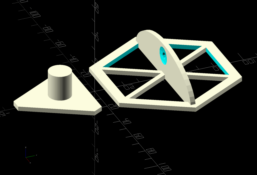
    if (Layout == "Build") {
    translate([1.5*TriRadius,-TriRadius,0])
    rotate(180/6)
    TriTemplate();
    translate([-1.5*TriRadius,-TriRadius,0])
    rotate(180/6)
    EndTemplate();
    translate([0,TemplateOD/2,0])
    HexTemplate();
    }

  • Pan Lid Handle Quieting

    Pan Lid Handle Quieting

    A surprisingly heavy stainless steel pan lid from the local ReStore has only one fault: when placed upside-down on the counter while we’re tending the pan contents, it will rock back and forth for nearly a minute. The lid has a rubberized insert for finger protection:

    Pan lid - original handle
    Pan lid – original handle

    However, the inserts cover only the side of the handle, so the metal arch rests on the counter. Setting it up in the shop let me scuff up the handle contact points:

    Pan lid - contact point
    Pan lid – contact point

    Then some Dremel grinding wheel work recessed the handle just barely below the inserts and changed the arch enough to keep it off the counter:

    Pan lid - recessed handle crest
    Pan lid – recessed handle crest

    The lid now stops rocking after a few seconds and is much quieter while doing so. It may require a bit more grinding, but it’s much better after this small intervention.