Ed Nisley's Blog: Shop notes, electronics, firmware, machinery, 3D printing, laser cuttery, and curiosities. Contents: 100% human thinking, 0% AI slop.
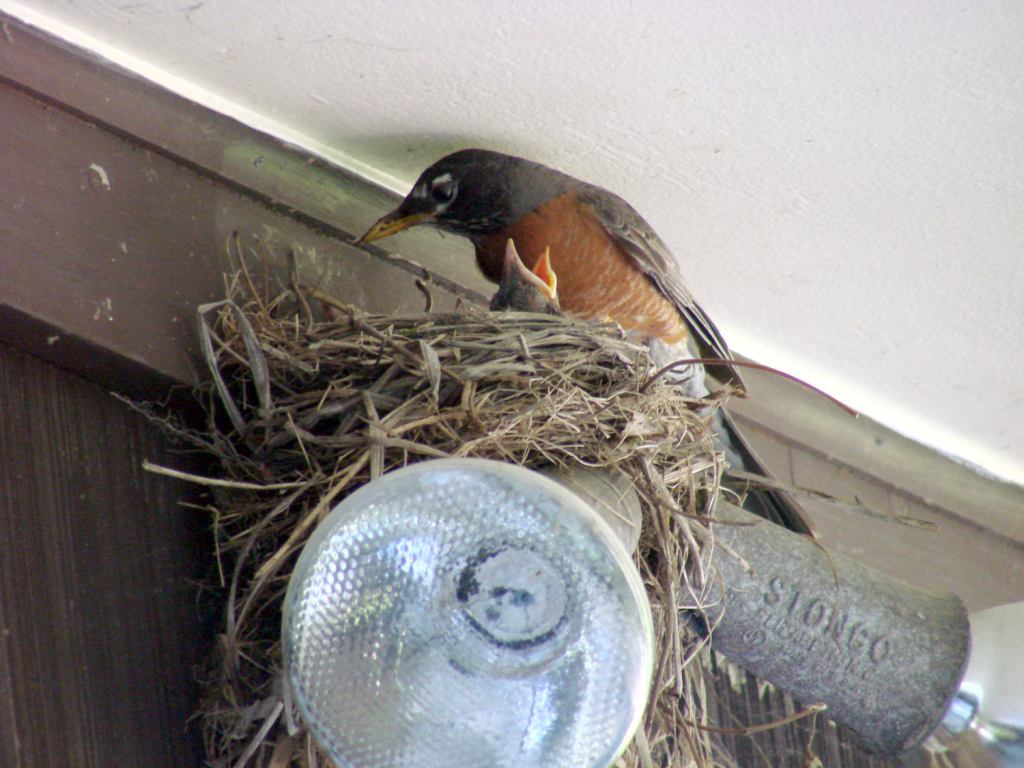
They’re recognizably robins now, covered in young-bird speckle camouflage.
Feeding continued apace:
Robin Fledging Day – feeding
After feeding, robin nestlings produce fecal sacs, which the parents either eat or carry away:
Robin Fledging Day – fecal sac
Robins aren’t big on facial expressions, but, speaking from personal experience, anything to do with diapers isn’t the high point of a parent’s day.
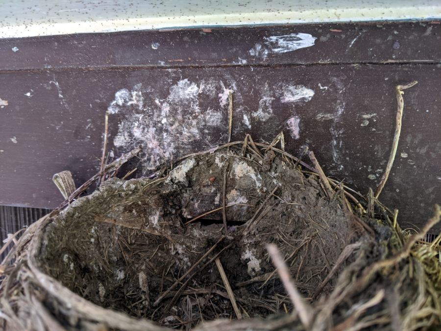
And then there were none:
Robin Fledging Day – empty nest with parasites
The gazillion black dots on the soffit are pinpoint-sized insects / mites / ticks infesting the nest and, presumably, the birds. The earlier pictures don’t show them, so perhaps these missed the last bird off the nest and are now regretting their life choices.
Nothing prizewinning, but better than no picture at all:
Garage Robin – recovered image
Note that you start by copying a reasonable chunk of the partition from the Memory Stick / (micro)SD Card first, to prevent a bad situation from getting worse.
Now I can remember the easy way the next time around this block …
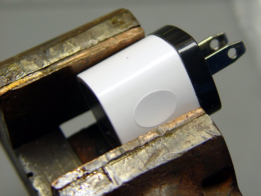
Start by grabbing opposite corners in a small vise and gently cracking the solvent-bonded joint between the sections:
Anon white charger – case cracking
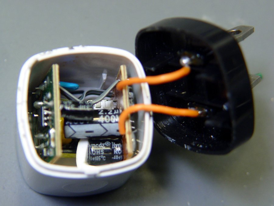
Pull the base past the molded latches:
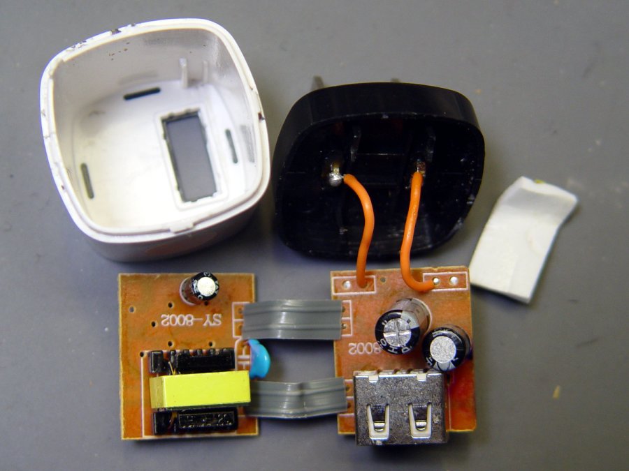
Anon white charger – case opened
Behold: components!
Anon white charger – PCB top
On both sides of both PCBs!
Anon white charger – PCB bottom
The top half of both boards, above the isolation cut, handles the line voltage and the lower half handles the 5 V USB output. You’ll note the absence of extra-cost parts like voltage feedback or ahem safety fuses.
Treating the whole regulator as a black box simplifies the schematic:
Anonymous white charger – schematic
The cap bridging the two sides should be a Y capacitor, but it’s an ordinary 1 nF ceramic cap with a generous 1 kV rating. As far as I can tell, having it inject AC line noise directly into the +5 V side of the USB supply is just a bonus.
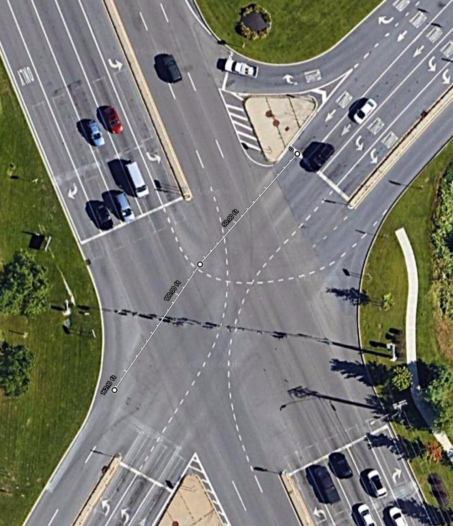
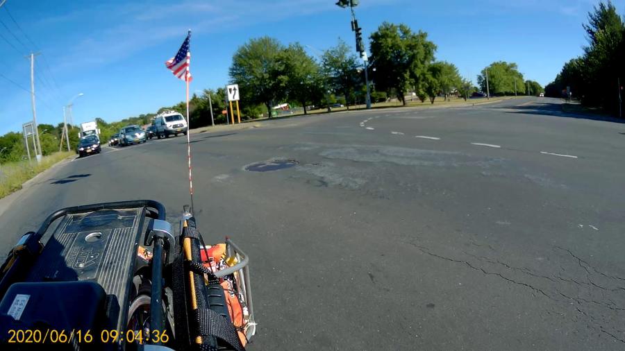
Our southbound bicycling routes take us through the intersection where Vassar Rd becomes NY Rt 9D at NY Rt 9. This is a large intersection:
Rt 9 Vassar Rd SB – distances
It’s worth noting that Rt 9D and Vassar Rd are also NYS Bicycle Rt 9., so bicycle traffic is expected, if not precisely welcomed.
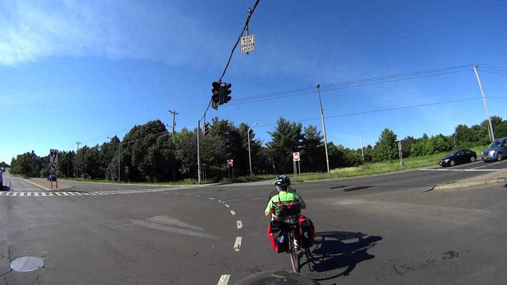
We’re traveling south on Vassar Rd, stopped in the right-hand lane (in the upper right of the picture). Eventually, the signal turns green:
Vassar Rd at Rt 9 – Green signal – 2020-06-21
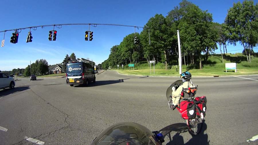
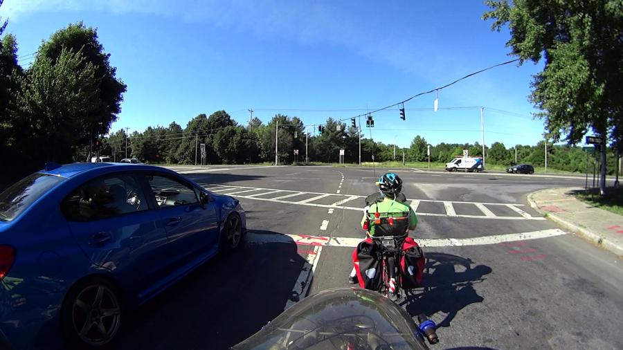
The traffic to our left starts moving, we start pedaling, and ten seconds later the signal turns yellow:
Vassar Rd at Rt 9 – Yellow signal at 10 sec – 2020-06-21
The traffic hasn’t cleared the intersection, either, but they’re moving faster than we are. The first distance marker on the map shows we’ve traveled 85 feet at an average 5.8 mph from a standing start.
After another five seconds, we’ve traveled 80 more feet (at 11 mph!), almost the far side of the intersection. Which is a good thing, because the signals on Rt 9 have already turned green and vehicles are accelerating toward us.
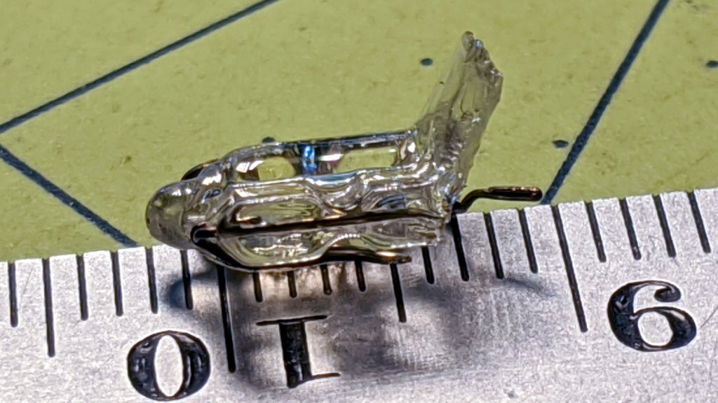
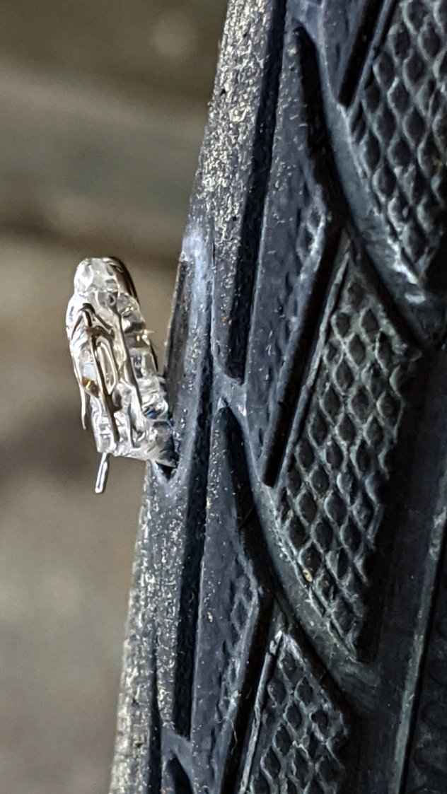
A clicking sound from the rear of the bike suggested something was amiss as I rolled up the driveway after a recent ride. Spinning the rear tire produced this alarming sight:
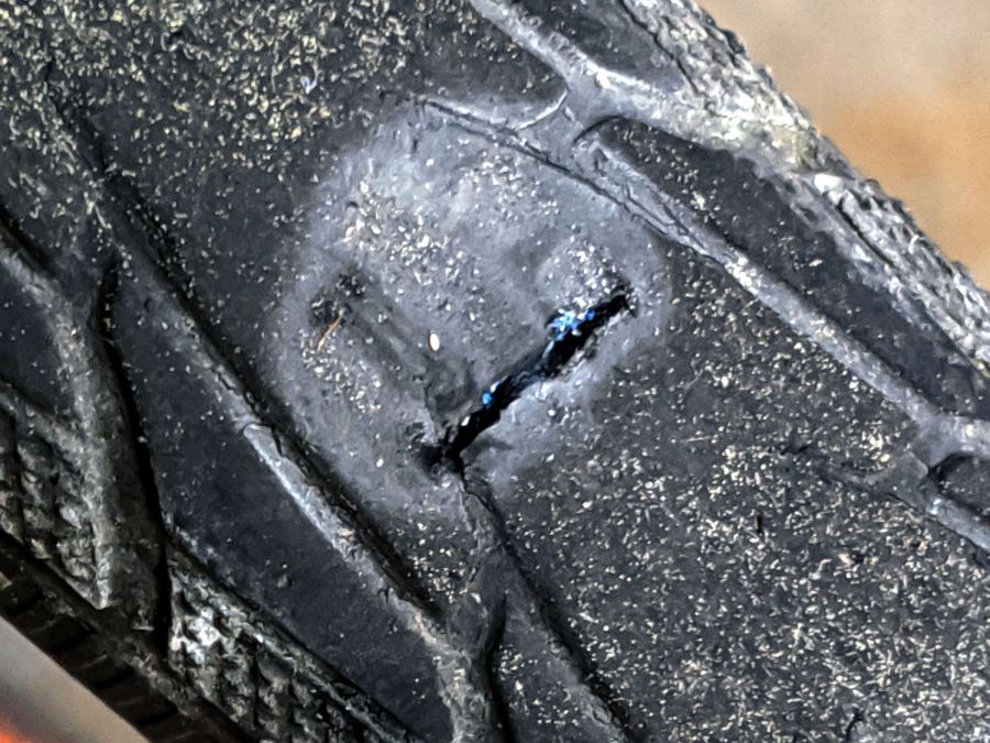
I cleaned the wound, filled it with silicone rubber, topped it with some duct tape, and it’s still holding air after a 13 mile ride. I think the gash cut through the rubber tread and SmartGuard layer, but didn’t affect the cords in the tire carcass, so keeping further road debris out of the gash should let the tire wear out more-or-less normally.
Putting duct tape on the tread will certainly help …
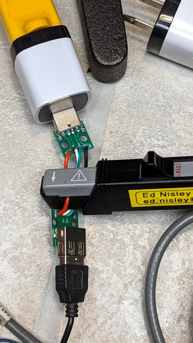
Looking at what comes out of various USB chargers, with the Tek current probe monitoring the juice:
USB Current-Probe Extender – in action
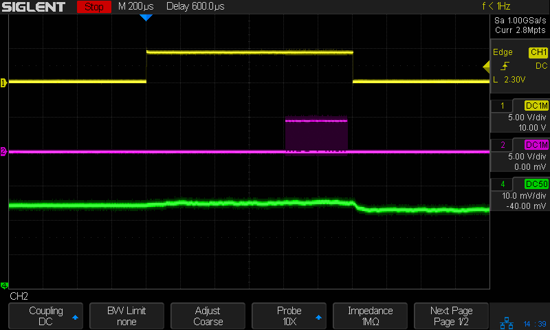
First, a known-good bench supply set to 5.0 V:
Tiles 2×2 – bench supply – 50 mA-div
The yellow trace is the Glass Tile Heartbeat output, which goes high during the active part of the loop. The purple trace shows the serial data going to the SK6812 RGBW LEDs. The green trace is the USB current at 50 mA/div, with the Glass Tile LED array + Arduino drawing somewhere between 50 and 100 mA; most of that goes to the LEDs.
The current steps downward by about 10 mA just after the data stream ends, because that’s where the LEDs latch their new PWM values. The code is changing a single LED from one color to another, so the current will increase or decrease by the difference of the two currents.
A charger from my Google Pixel 3a phone (actually made by Flextronics and, uniquely, UL listed), with Google’s ever-so-trendy and completely unreadable medium gray lettering on a light gray plastic body:
Google Pixel charger – dataplate
The current waveform looks only slightly choppy:
Tiles 2×2 – Google Flextronics charger – 50 mA-div
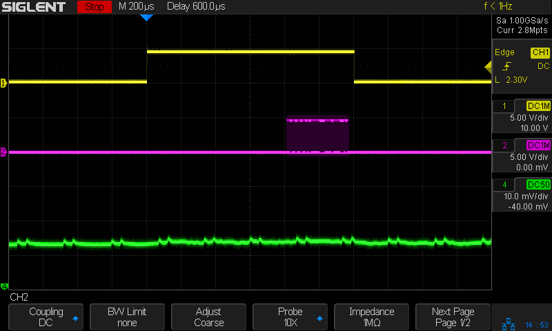
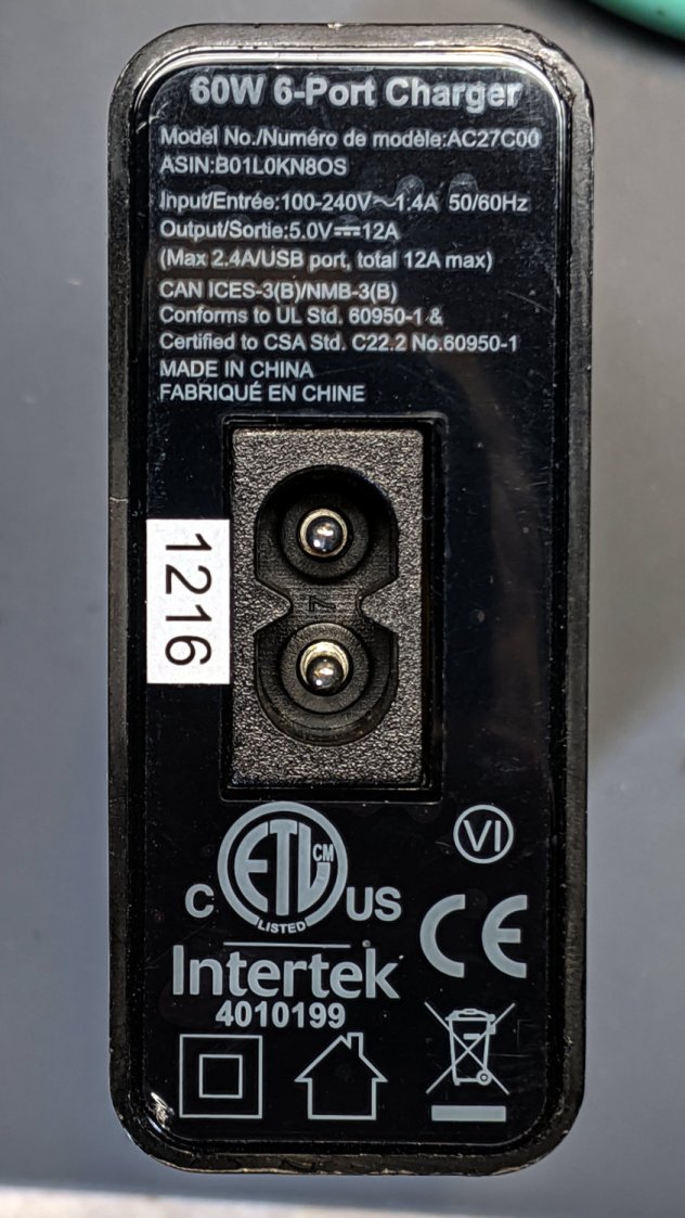
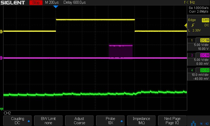
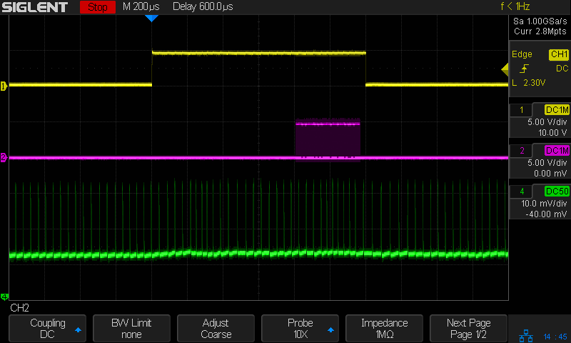
An AmazonBasics six-port USB charger from tested by Intertek:
From the 75 mA baseline, the charger is ramming 175 mA pulses at 24 kHz into the filter cap on the Arduino Nano PCB! The green trace has a few seconds of (digital) persistence, so you’re seeing a lot of frequency jitter; the pulses most likely come from a voltage comparator controlling the charger’s PWM cycle.
It’s about what one should expect for $1.28 apiece, right?
They’re down to $1.19 today: who knows what the waveform might be?