The Smell of Molten Projects in the Morning

Ed Nisley's Blog: Shop notes, electronics, firmware, machinery, 3D printing, laser cuttery, and curiosities. Contents: 100% human thinking, 0% AI slop.

Author: Ed

  • Sherline CNC Mill: Y-Axis Nut Mishap

    Sherline CNC Mill: Y-Axis Nut Mishap

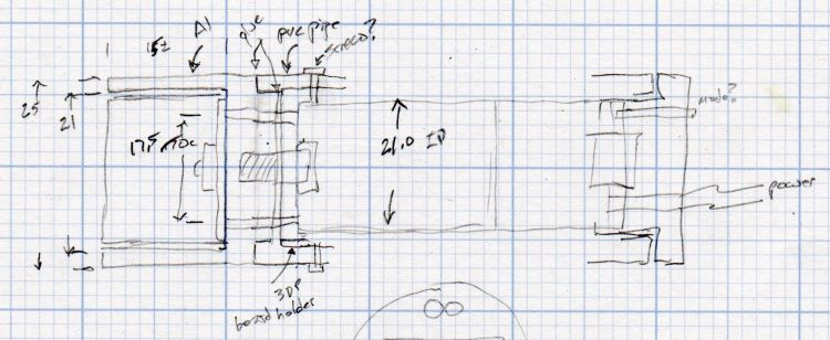
    The need to gnaw a V groove into the side of two 60 mm aluminum bars led to this Sherline CNC mill setup:

    Sherline Y-Axis Nut Mishap - setup
    Sherline Y-Axis Nut Mishap – setup

    Milling the near end of the bars put the angle plate’s rear lock screw within a millimeter of the column; the vise fits in exactly one spot on the angle plate and that’s where the jaws must be.

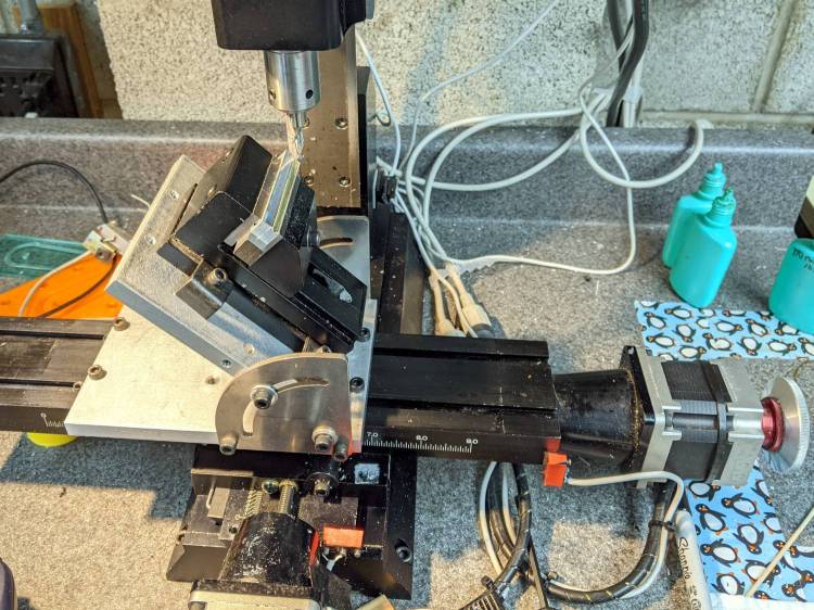
    While controlling the mill with the Joggy Thing and some manual command entry, because it’s easier than real CNC programming, I overshot the near end and rammed the column with enough enthusiasm to dislodge the Y-axis leadscrew nut. An interlude of utter confusion ended with the backlash preload nut firmly jammed against the leadscrew coupler on the other end of travel:

    Sherline Y-Axis Nut Mishap - stuck preload nut
    Sherline Y-Axis Nut Mishap – stuck preload nut

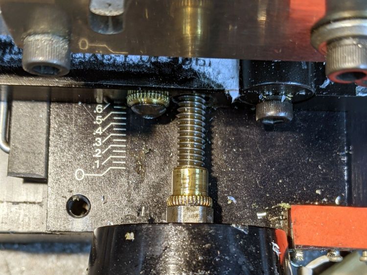
    The paper shreds show where the bellows formerly stuck on the Y axis stage.

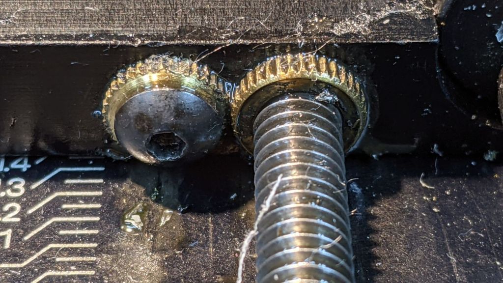
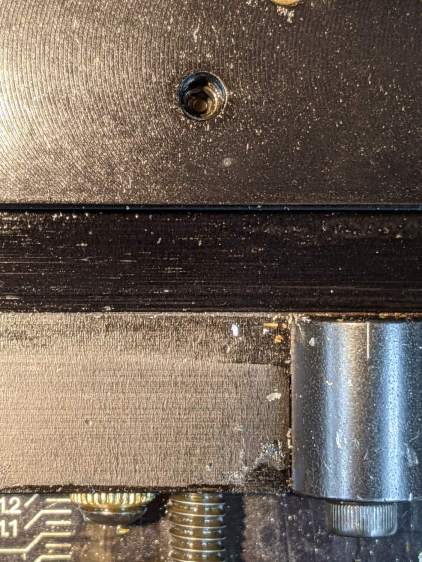
    The backlash nut chewed off a few star lock gear teeth on its way out, as seen here just above where they mesh:

    Sherline Y-Axis Nut Mishap - chewed star nut
    Sherline Y-Axis Nut Mishap – chewed star nut

    It’s been quite a few years since I took the thing apart to replace the nuts, so I used the opportunity to lube the otherwise inacessible X axis leadscrew inside its table upside down on the bench.

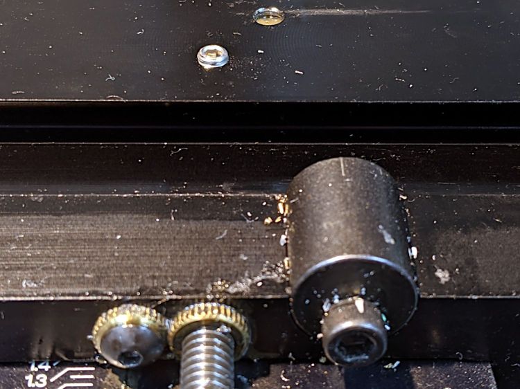
    The setscrew locking the Y axis leadscrew nut in place heaves into view with the X axis table off:

    Sherline Y-Axis Nut Mishap - setscrew
    Sherline Y-Axis Nut Mishap – setscrew

    I thought about jamming it in place with a second 10-32 setscrew, but the ones on hand were just an itsy too long and collided with the X-axis table:

    Sherline Y-Axis Nut Mishap - doubled setscrew
    Sherline Y-Axis Nut Mishap – doubled setscrew

    The thought of having the additional setscrew work loose, grind into the underside of the table, and require major surgery for recovery persuaded me to drop it back in the drawer.

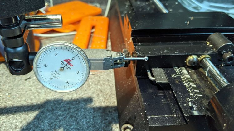
    With everything in place, I adjusted the backlash (on both axes) down to a few mils:

    Sherline Y-Axis Nut Mishap - backlash test
    Sherline Y-Axis Nut Mishap – backlash test

    Tweaking the X axis preload nut under the table is not my idea of a good time, but it’s been quite a while since I had to do that.

    Folding the new paper bellows and installing them took about as long as repairing the mill.

    Milling the second V groove worked fine; all is right with the Sherline again.

  • Soldering Iron Spider

    Soldering Iron Spider

    I noticed something out of place when I fired up the soldering iron:

    Soldering Iron Spider
    Soldering Iron Spider

    It’s not obvious in a flat photo without depth perception, but here’s a closer look:

    Soldering Iron Spider - detail
    Soldering Iron Spider – detail

    A tiny spider had set up shop just over the tip cleaning port, with a delicate web linking the sponge to the iron holder.

    I tried to deport her outdoors, as is our custom with helpful critters, but she jumped off the web and scurried to an unknown spot on the bench. She’ll surely rebuild in an equally productive spot.

    Obviously, I’m not soldering enough electronic gadgetry …

  • Running Light: 1 W LED Switched Parallel Resistors

    Running Light: 1 W LED Switched Parallel Resistors

    Manually selecting the current through the 1 W amber LED with a switch actually intended for LED flashlights:

    1 W LED Running Light - switched parallel R
    1 W LED Running Light – switched parallel R

    The resistors on the low side of the LED use the MP1584 regulator for current control, with the orange wire feeding the resistor voltage into the error amplifier.

    The 15 Ω unswitched resistor sets the LED current at 53 mA = 0.8 V / 15 Ω, with the LED dissipating about 100 mW. The resistor dissipates 43 mW.

    Closing the switch puts the two parallel 4.7 Ω resistors in parallel with the 15 Ω resistor to produce 2.0 Ω, which sets the LED current to 390 mA and runs it at 950 mW. Each of the 4.7 Ω resistors dissipates 140 mW.

    That much power raises the aluminum body to 50 °C = 120 °F: definitely uncomfortable but probably survivable for the LED inside.

    Eyeballometrically, a decimal order of magnitude difference in the LED current produces an obvious brightness difference. My first try ran the LED at 500 mW (a binary order of magnitude less than 1 W) and wasn’t visually different. Given that the LED will run from the Bafang’s headlight output, saving power isn’t all that important.

    If this is the first time you’ve encountered parallel resistors, this is why your calculator has a reciprocal button: the total resistance is the reciprocal of the sum of the reciprocals of all the resistances:

    1/R = 1/R₁ + 1/R₂ + …

    A real engineering calculator does not have a shifted reciprocal function.

  • Running Light: 1 W LED Heatsink

    Running Light: 1 W LED Heatsink

    The general idea: a cylindrical holder / heatsink for a 1 W LED on the end of a tube clamped in a Tour Easy fairing mount, much like a flashlight.

    A pleasant evening at a virtual Squidwrench meeting produced the raw shape of the front end from a 1 inch aluminum rod:

    1 W LED Running Light - heatsink raw
    1 W LED Running Light – heatsink raw

    Trace the outline of the LED’s PCB inside the cylinder just for comfort, align to the center, and drill two holes with a little bit of clearance:

    1 W LED Running Light - heatsink drilling
    1 W LED Running Light – heatsink drilling

    For the 24 AWG silicone wire I used, a pair of 2 mm holes 8.75 mm out from the center suffice:

    1 W LED Running Light - heatsink fit
    1 W LED Running Light – heatsink fit

    Gnaw some wire clearance in the lens holder:

    1 W LED Running Light - wiring
    1 W LED Running Light – wiring

    Tap the central hole for an M3×0.5 screw, which may come in handy to pull the entire affair together.

    Epoxy the PCB onto the heatsink with the lens holder keeping it aligned in the middle:

    1 W LED Running Light - heatsink clamp
    1 W LED Running Light – heatsink clamp

    Then see how hot it gets dissipating 900 mW with 360 mA of current from a 2.2 Ω resistor:

    1 W LED Running Light - heatsink test
    1 W LED Running Light – heatsink test

    As you might expect, it gets uncomfortably warm sitting on the bench, so it lacks surface area. The first pass will use a PVC cylinder for easy machining, but a full aluminum shell would eventually be a nice touch.

    A doodle with some dimensions and aspirational features:

    Running Light - 1 W LED case doodle
    Running Light – 1 W LED case doodle

    Even without a lens and blinkiness, it’s attention-getting!

  • Google Play Store Ad Bidding Delay

    Google Play Store Ad Bidding Delay

    Being that type of guy, I turn my phone off during the night while it’s charging, turn it on for the next day’s adventures, and check the Google Play App Store to see which apps will get updates.

    The vast machine learning / AI / whatever analyzing my every move still hasn’t figured out my morning ritual, so it desperately tries to sell me crap:

    Google Play Store - app ad delay
    Google Play Store – app ad delay

    My guess: those blank spots are placeholders for app ads, but, while the phone is busy scanning for malicious apps, the ad bidding process doesn’t complete fast enough to update the display before I see it.

    FWIW, I had the Genuine NYS Covid-19 app installed for a while, but I very rarely go anywhere or see anybody, so it seemed to offer no net benefit.

  • Sticky Trap Results

    Sticky Trap Results

    In late May we deployed six sticky traps in and around the onion bed, attempting to reduce the number of Onion Fly maggots. By mid-June the sheets were covered with the shredded leaves Mary uses to mulch the onions, but half a dozen flies were out of action:

    Sticky trap - 2021-06
    Sticky trap – 2021-06

    We’re pretty sure that’s what these things are:

    Sticky trap - Onion Fly - 2021-06
    Sticky trap – Onion Fly – 2021-06

    They’re supposed to have red eyes, but being affixed to a sheet of snot for a few weeks doesn’t do the least bit of good for your eyes.

    We replaced the sheets and left them in place until the end of July:

    Sticky trap - 2021-07
    Sticky trap – 2021-07

    The sheets took another half-dozen flies out of circulation, Mary began harvesting the onions, and observed it was the healthiest onion harvest she’s ever had.

    We declared victory, removed the traps, and the remaining onions suffered considerable maggot damage over the next few weeks.

    Anecdotally, it seems reducing the Onion Fly population by (what seems to be) a small amount and maintaining pressure on the population dramatically reduces the number of maggots available to damage the onion crop. At least for a single bed in a non-commercial setting.

    The plural of anecdote is not anecdata, but we’ll try it again next year, leave the traps in place while the onions are in the ground, and see what happens.

  • MP1584 Current Regulator: Arduino Blinkiness

    MP1584 Current Regulator: Arduino Blinkiness

    Mostly because I wanted to verify that it really worked:

    MP1584 current - red LED - Arduino blinkiness
    MP1584 current – red LED – Arduino blinkiness

    The Arduino Nano runs the default Blink program that all the knockoff manufacturers use as their final QC test.

    The MP1584 specs say the Enable input can accept a logic signal up to 6 V, the Nano runs at 5 V regulated down from the 6.3 V from the bench supply, and the 1 W red LED now flashes 1 s ON / 1 s OFF.

    The current feedback works as it did before, too, which is comforting.

    The Nano adds 20 mA to the bench supply, so the whole affair runs at 220 mA = 1.4 W. Of course, it’s now at a 50% duty cycle, so that helps.

    I doubt hand-hewing an astable multivibrator is the right way to add blinkiness, but it’d definitely be playing on hard mode.