Ed Nisley's Blog: Shop notes, electronics, firmware, machinery, 3D printing, laser cuttery, and curiosities. Contents: 100% human thinking, 0% AI slop.
Apparently the stink bug’s armor doesn’t count for much when the spider has the luxury of attacking through a weak spot in the underbelly after the critter stops struggling.
Stink bugs cause considerable damage to crops (notably apples) in the Hudson Valley, but they haven’t been the existential catastrophe we all expected when they first arrived.
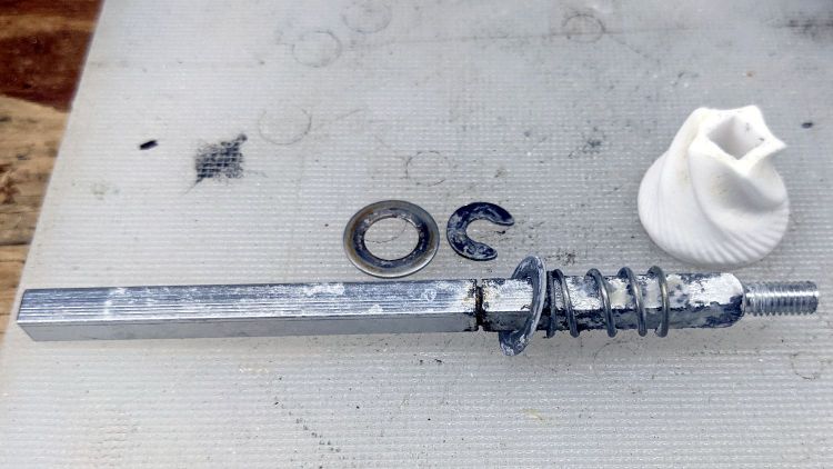
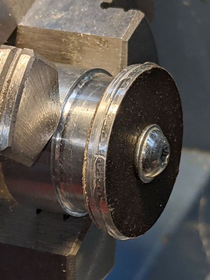
It turns out the somewhat corroded square shaft is aluminum, neither the cheap steel I expected nor the stainless steel it should be. Perhaps OXO cost-reduced the shaft, discovered aluminum is a poor choice in a saline environment, and changed the packaging to compensate?
Removing / installing the Jesus clip requires careful whacking with a hollow-tip punch against the shaft, with the whole affair laid flat on shop towels, the handle held down to prevent rotation, and the wrap-around body capturing the escaping clip.
Shaft corrosion as of Summer 2020:
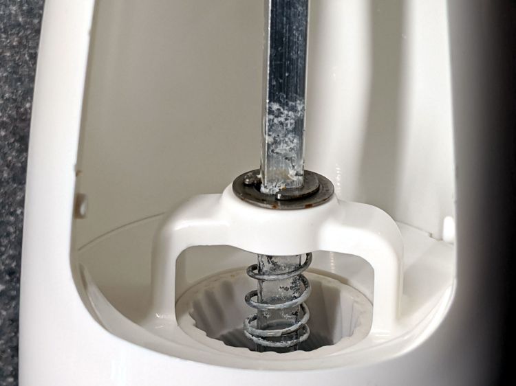
OXO Salt Mill – corrosion
Soaking the body in hot water got rid of salt crusts and filled the shell with water. There being no way to completely dry the thing, I parked it in the sun for a day, refilled it, and was unsurprised when the (dried) salt turned into an assortment of moist crystals.
Installing Atkinson Hyperlegible reminded me to clear out the Noto font clutter in this (relatively recent) Manjaro installation. Of course fonts now appear in slightly different locations with slightly different names, so this remains just a serving suggestion:
For unknown reasons, we now have two font cache updaters:
sudo fc-cache -v -f
sudo fc-cache-32 -v -f
Now font selection in, say, LibreOffice doesn’t involve paging through a myriad fonts in languages I cannot recognize, let alone read. Admittedly, Inconsolatadoes have more variations than I’ll ever use.
I’ll be talking about e-bikes and the solid modeling required to hang a Bafang motor and battery on your favorite bike for the Poughkeepsie Chapter of the ACM at 1930 EDT this evening:
Bafang Battery Mount – Show view
It’s a Zoom meeting, so (in the unlikely event you have nothing better to do) you could actually “attend”. The ACM meeting description and the Meetup announcement will get you there.
A PDF of the presentation slides (remember slides?) includes copious linkies to sources / blog posts / distractions:
Having just replaced Rev 1 of the amber running light with Rev 3 (about which, more later) on Mary’s Tour Easy, both the front and rear lights began blinking erratically. Given that they have completely independent circuitry, this strongly suggests a power problem.
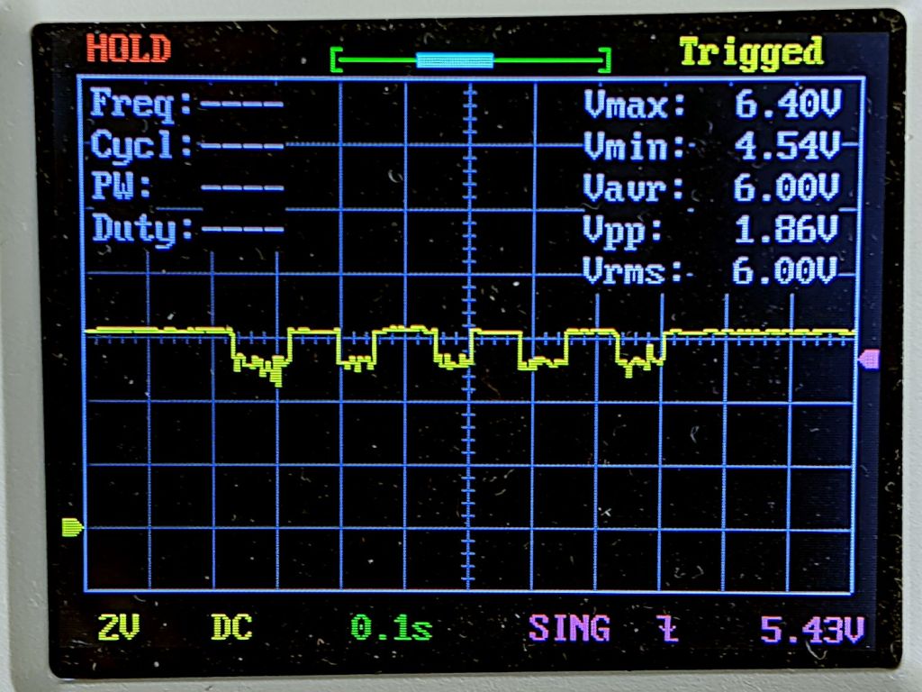
Herewith, the headlight circuit voltage:
Bafang headlight voltage – two 1 W running lights
The voltage should be a constant 6 or 6.3 V, depending on which description you most recently read. That is the case with only one light attached, so the problem occurs only when running both lights.
The four pulses come from the amber LED’s Morse code “b” (dah-dit-dit-dit) with a 85 ms dits; the first dah pulse should be three times longer than the dits and definitely isn’t. The rear light’s red LED stays on continuously, except for two dark dits, so it draws a constant current and does not produce any changes in this trace.
Both lights have 2.0 Ω sense resistors setting the LED current to 400 mA, which corresponds to 250 mA each from the Bafang controller’s 6.3 V headlight circuit. The headlight circuit’s total of 500 mA should work fine, although the “spec” seems to be basically whatever the OEM headlight requires.
The Rev 1 amber light ran the LED at 360 mA with a supply current around 450 mA. That light and the rear light on the back ran fine, so the supply seems to have a hard maximum current limit at (a bit less than?) 500 mA.
The least-awful solution seems to be backing off both LED currents to 360 mA to keep the total supply current well under 500 mA.
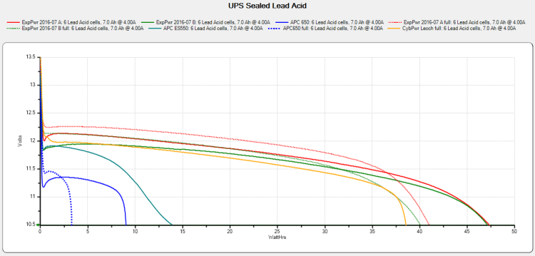
The UPS coddling the M2 printer began complaining about a bad battery, so I ran (nearly) all the UPS batteries through the tester:
UPS SLA 2021-10-10
The two blue flubs in the lower left come from the failed battery, with the dotted trace after charging to 13.7 V and letting the current drop to 20 mA.
The red and green traces come from two other UPS batteries installed in 2016, with the dotted traces after charging similarly. The orange-ish trace is from the battery in a Cyberpower UPS bought in 2016, so it looks like all batteries of that vintage fade equally.
Except for another pair of batteries in another UPS that had discharged stone cold dead; it may have been shut down and unplugged during a power outage and they never quite recovered.
After five years, it’s time to refresh the fleet …