Ed Nisley's Blog: Shop notes, electronics, firmware, machinery, 3D printing, laser cuttery, and curiosities. Contents: 100% human thinking, 0% AI slop.
This is the season for erecting the structures upon which the pole beans will climb:
Garden Bean Poles – overview
They’re made from a dozen small trees and branches of larger trees harvested around the yard. They last for a few years, just long enough for the next crop to reach useful lengths.
We lash them together with fabric strips:
Garden Bean Poles – joint detail
My knot hand is weak, but seems sufficient to the task.
Mary formerly tore the strips from old jeans / pants / whatever, which required considerable effort, produced ragged edges, and filled the air with fabric dust. This year, I proposed an alternative:
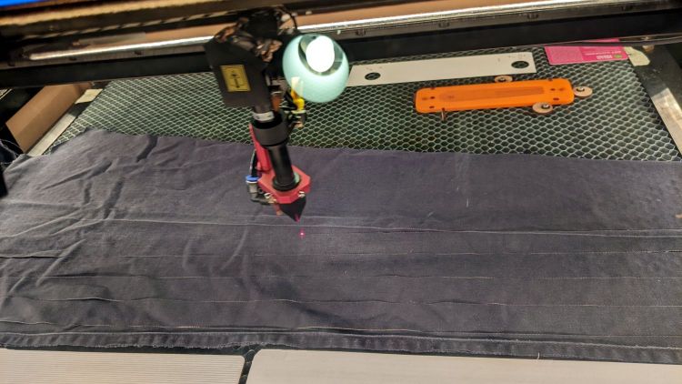
Garden Bean Poles – laser cutting ties
The weird thing in the middle is a reflection of an overhead can light in the laser cabinet’s polycarb lid.
From starting the LightBurn layout to presenting the strips for final inspection required the better part of ten minutes. I scissors-cut along the main seams to get single fabric layers, with everything above the crotch seam wadded off the platform to the left.
As with my shop raglets, the layout depends on LightBurn’s overhead camera view to align the cuts with the fabric on the platform:
Bean Pole Ties – LightBurn layout
It’d be easier to see with lighter fabric, but that’s what came to hand in the scrap box and the beans won’t care. We do not anticipate complaints about the odor of charred fabric when they reach the top of the poles, either.
The strips must align with the fabric’s grain to put the warp threads along their length, which makes the main side seam parallel to the X-axis. Even I can handle that layout!
Yes, the strips have rounded corners and, no, it doesn’t matter.
Not knowing what to expect, I peeled the protective plastic off the styrene PETG sheet before cutting the perimeter, thereby dooming myself to about five minutes of polishing with Novus 2 to remove the condensed vaopor and another five minutes restoring the shine with Novus 1. Next time, I’ll know better.
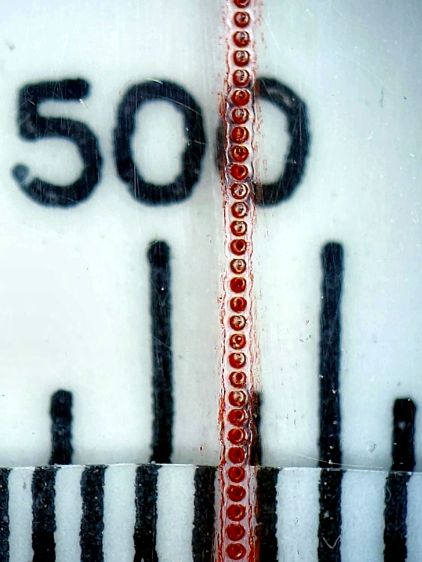
Eyeballometrically, the hairline is a lovely fine line, but it’s really a series of craters on 0.25 mm centers filled with red Pro Sharpie marker and wiped off with denatured alcohol:
Tek CC – laser-etched cursor hairline – detail
That’s dot mode: 2 ms pulses at 20% power (about 12 W) with a line speed of 100 mm/s and 0.25 mm dot spacing. The craters look to be 0.15 mm in diameter, with a 0.15 mm blast radius merging into a line along the sides. The view is looking through the undamaged side of the cursor, so you’re seeing the craters from their tips.
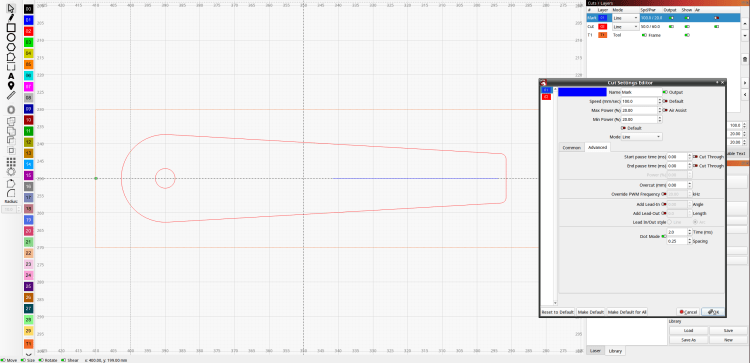
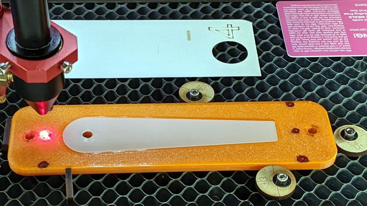
I cut the cursor and engraved / etched the hairline in one operation, by just laying a rectangle on the honeycomb and having my way with it:
The six pips (small printed holes with ugly black outlines) intended for the Sherline’s laser aligner make this feasible, although the accuracy of the OMTech’s laser pointer requires precisely setting the focal point atop the fixture.
The corners of LightBurn’s tooling layer (the enclosing rectangle) match the corner pip positions, so framing the pattern should light up those four holes. Putting the Job Origin (small green square) at the center-left point lets me tweak the machine’s origin to drop the alignment laser into that pip.
AFAICT, burning a cute puppy picture pretty close to the middle of a slate coaster makes everybody else deliriously happy.
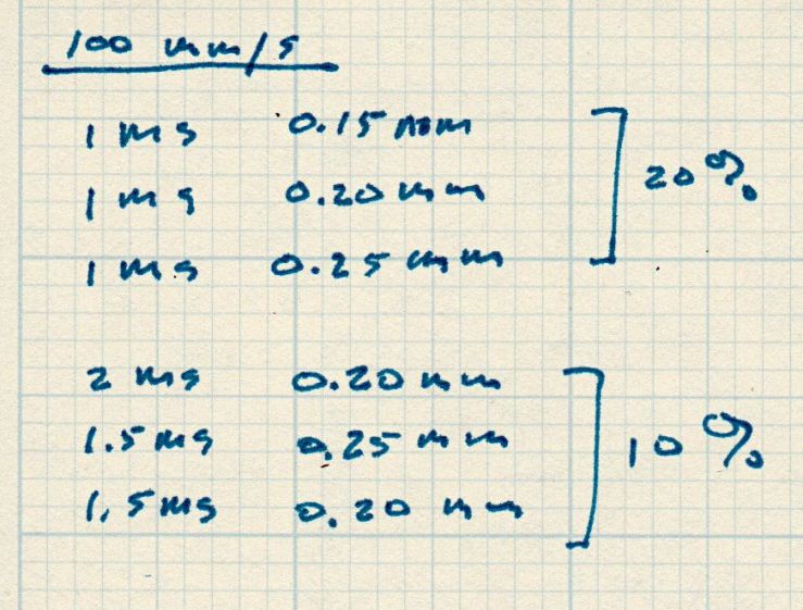
Setting up the cut layer parameters:
Tek CC Cursor – laser dot mode tests
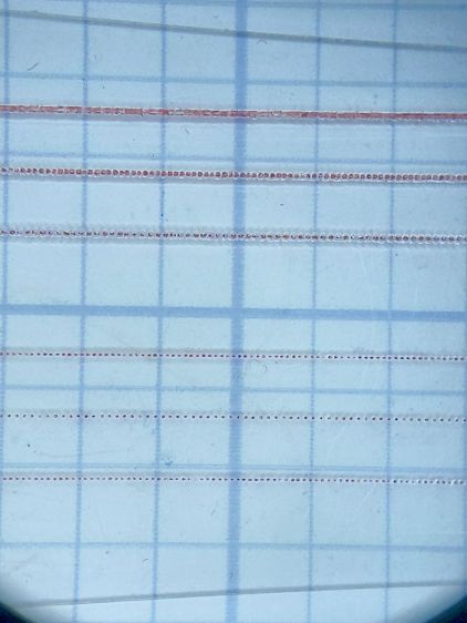
Burning through the protective film, peeling it off, filling with Sharpie, and wiping with alcohol produces interesting results against a 0.1 inch = 2.54 mm grid:
Tek CC Cursor – dot mode 1-2ms 10-20pct
The angled top and bottom lines are the edges of the cursor, positioned with the craters on the top surface.
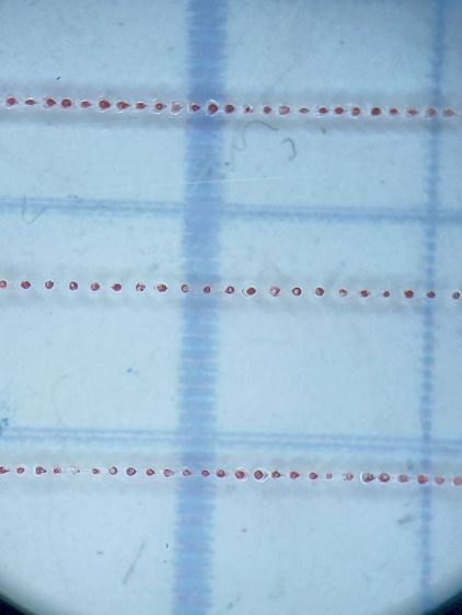
The bottom three lines at 10% power consist of distinct 0.10 mm craters incapable of holding much ink:
Tek CC Cursor – dot mode 2ms 10pct
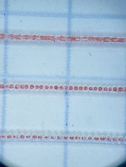
The top three lines at 20% power have 0.15 mm craters and look better:
Tek CC Cursor – dot mode 1ms 20pct
The top line was a complete surprise: it seems a 20% duty cycle does not turn off completely between 1 ms dots spaced at 0.15 mm. I expected a row of slightly overlapping dots, which is obviously not what happens.
Punching the dots through the protective film eliminated the polishing operation, although I have yet to cut the perimeter with the film in place.
More experimentation is in order, but it looks like I can finally engrave good-looking and perfectly aligned hairlines on nicely cut cursors without all those tedious manual machining operations.
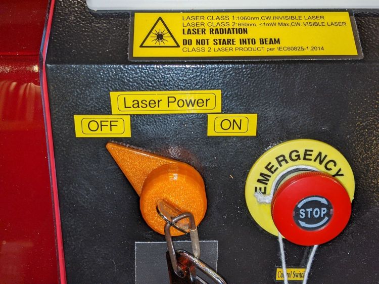
It is in series with the lower switch on the side panel:
OMTech Laser – rocker switch lit
Although I would have labeled those switches differently, the “Control Switch” handles the 120 VAC line voltage to the HV power supply. As you’d expect, when its light is ON, the power supply is also ON and the laser is ready to fire.
Those two pictures show the situation after I turned the laser power on a few days ago: key lock switch OFF, HV laser power supply stubbornly ON.
Whoops.
The “Control Switch” still does what it should, so I can shut the HV supply off when it’s not needed, but the key lock switch has definitely failed ON.
As far as I can tell, the moving contact bar jammed at the bottom of its travel against the terminals. Pulling the switch out of the laser jostled it enough to release the bar and it’s now at the top of its travel:
OMTech Laser – key lock – side view
If it failed once, it’ll fail again.
OMTech’s Customer Support agrees it shouldn’t behave like that; a replacement should arrive in a few days.
Wiping down a tool or wiping up a mess with a small rag and then throwing it out simplifies cleanup:
Shop wipes
Long ago, I applied scissors to old towels / t-shirts / whatever to get randomly sized squares, but when Mary began using rotary cutters for her sewing projects I immediately saw the light. A few times a year, I lower the scrap box level and restock the shop wipes boxes.
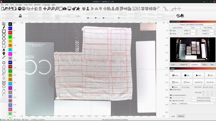
A laser cutter is even better:
Shop Rags – LB camera layout
Flatten the rag on the honeycomb, drag a few rectangles into place, and fire the laser:
Shop wipes – laser cut
Something like 50 mm/s at 60% power works for all the fabrics I’ve tried, from worn-out towels and dead sweatpants to napkins and t-shirts. Thinner fabrics can be stacked, but wrinkles and seams get in the way of clean cuts.
Rounded-corner rectangles are easy enough to draw and the scrap cloths have different shapes, so I don’t see much point in saving a file with any specific layout. Your scrap box may be more orderly.
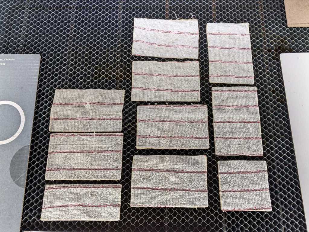
A clean cut lets the outer cloth just lift away:
Shop wipes – on honeycomb
The wipes give off a distinct smell of charred cloth, but running them through the clothes washer in a big mesh bag with everything else solves that problem.
Obviously, one couldn’t possibly justify a laser cutter to make shop wipes, but if you happen to have one just standing around, well …
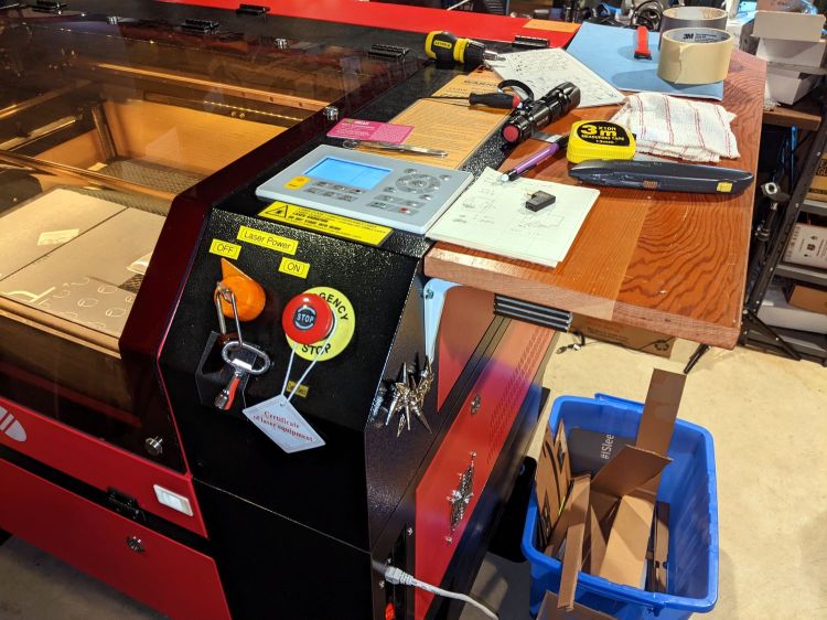
The OMTech laser manual specifically warns against allowing clutter to accumulate atop the cabinet:
It is highly recommended to have an extra work table nearby in order to avoid placing objects on or directly adjacent to the machine, which could become a fire or laser hazard.
OMTech USB570c Cabinet Laser Engraver User Manual
The Basement Shop lacks the floor space for their recommended “extra work table”, so the laser cabinet now sports a pair of wings:
They’re a convenient 9 inches wide, just right for general clutter. That stubby screwdriver encroaching on the lid shows I haven’t been entirely successful.
Each white shelf bracket has three self-tapping machine screws driven into the wood and a single 4 mm SHCS through a hole drilled into the cabinet with a nyloc nut & washer on the inside. If I understand the somewhat abbreviated instruction sticker correctly, I installed them upside-down in order to put the longer end under the wood where it would do the most good; they’re entirely rigid enough for the purpose.
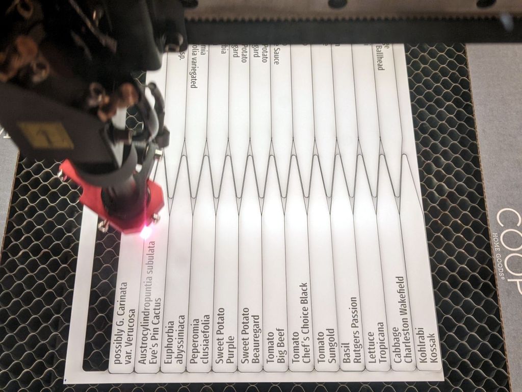
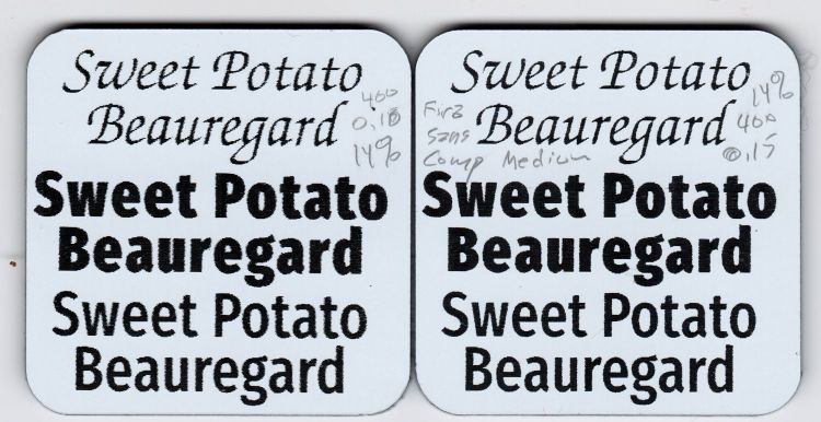
Putting two lines of the most-readable font inside an outline reverse-engineered from a few handwritten samples let me cut out a bunch of plant markers from white-on-black Trolase acrylic:
Plant Markers – cutting
Which look downright dignified in real life:
Plant markers – African Violet
Admittedly, sweet potato slips don’t require such extensive documentation:
Plant Markers – sweet potatoes
Cutting the sheet flat on the honeycomb platform worked well, modulo Sadler’s warning about cutting acrylic, and a few smudges on the back of the markers will go unnoticed.
The codes give the position and format for text fields in a CSV file containing one line for each tag:
Austrocylindropuntia subulata,Eve’s Pin Cactus
Euphorbia,abyssiniaca
possibly G. Carinata,var. Verucosa
African Violet,Maui
Sansevieria trifasciata,Mother in law’s tongue
Plectranthus,'Mona Lavender'
The rules governing quoted strings and suchlike remain to be explored, but single quotes in the CSV file pass through unchanged.
Putting a tab at the point of the marker will prevent it from falling free when cut out, should you want to try raising the sheet above the platform to reduce the amount of crud accumulating on the back side.
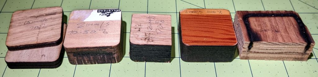
I thought a pine plank would cut faster than oak, but they’re equally stubborn.
Maple requires slightly more power, with the glued butt joints between the slabs putting up a stiff resistance.
A sheet of 3 mm MDF cuts well at 20 mm/s 60% and I expect 3 mm plywood might need similar numbers.
A pervasive odor of burned wood seems to be the only downside; if you think a wood stove is a good idea, you’ll love laser cutting the stuff. Sanding the blackened perimeter and sealing the surface surely helps, but it’s feasible only for the kind of simple convex shapes you don’t really need a laser to cut.