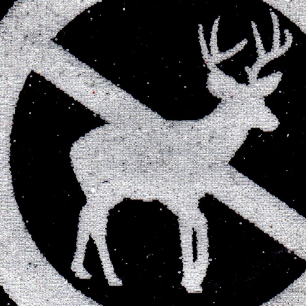
The fuzzy edges engraved on the acrylic test sample showed the need for scan offset adjustment:

The problem arises from the finite delay between the controller turning the laser beam on and the rise time of the death ray energy at the focal point.
LightBurn can produce a calibration coupon (on Trolase laminated acrylic) to help explore the multidimensional parameter space:
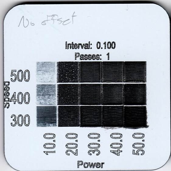
The “Interval” value is the vertical (Y-axis) scan line spacing. The laser spot diameter is, at absolute best, about 0.2 mm on the focal plane, with the actual engraved line being smaller due to the energy distribution across the beamwidth and the power required to visibly damage the material, so a 0.1 mm interval should result a little bit of overlap between adjacent scan lines.
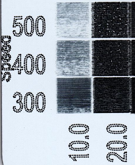
A closer look shows the serrated edges on the left and right sides of the engraved squares:
Peering at it through a measuring magnifier suggests the offset is a bit over 0.2 mm at 400 mm/s, corresponding to a 500 µs delay between laser turn-on in the rightward direction and turn-off in the leftward direction.
The LightBurn Scanning Offset Adjustment is half the measured distance, with an Initial Offset parameter to adjust the starting point of the first scan line. You measure the distance at each speed and fill in the table accordingly.
Iterating through offsets, speeds, powers, and intervals produces a series of test coupons slicing through the parameter space:
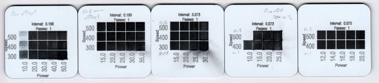
All in all, a 0.1 mm offset at 400 mm/s with 14% power (about 8 W) and 0.075 mm interval looks pretty good:

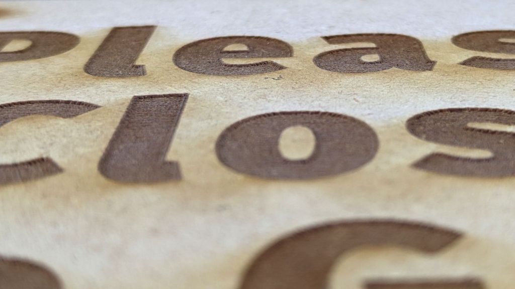
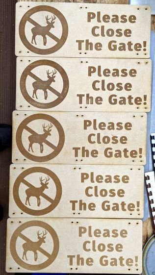
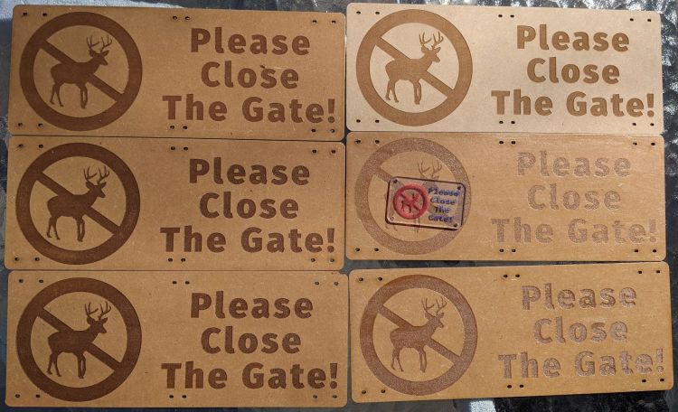
Engraving various fonts:
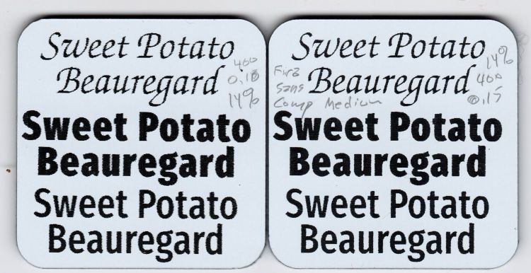
A closer look (left coupon on the top):
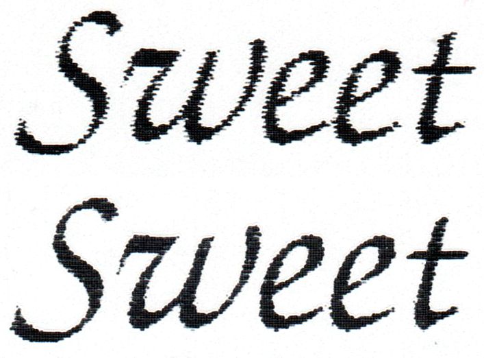
LightBurn linearly interpolates between table entries of offset values at specific speeds, so you must fill in several lines to give it something to munch on. The top text came from an offset table with two entries at 400 and 500 mm/s, which obviously wasn’t quite sufficient. The bottom text comes from a three-entry table:

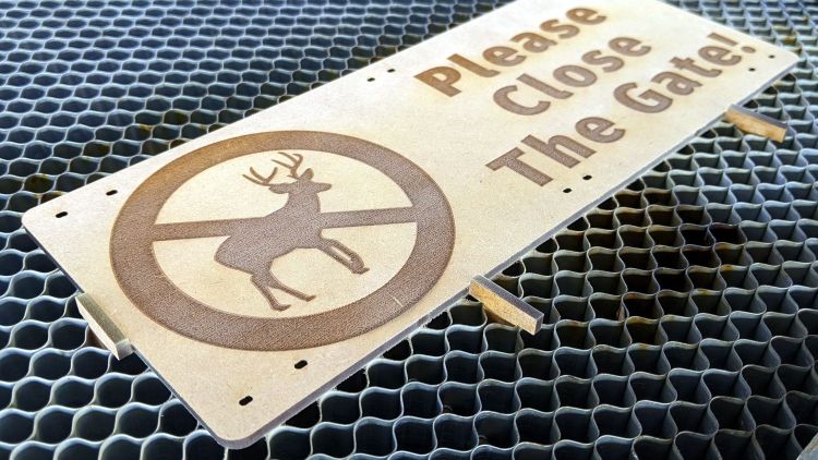
Which produces a better result, even at 500 mm/s and 20% power (12 W) on scrap acrylic:
A closer look:

Much better!


