Ed Nisley's Blog: Shop notes, electronics, firmware, machinery, 3D printing, laser cuttery, and curiosities. Contents: 100% human thinking, 0% AI slop.
We deployed six sticky traps in the onion patch immediately after planting in late April and replaced the cards in mid-June. The first set of cards collected a considerable number of what resemble, to my untrained eye, onion maggot flies and the onion plants remain healthy:
Each image shows both sides of a single card.
The cards sit a foot above the shredded leaf mulch and I managed to drop at least one of the cards while extracting it from the cage, but they all have plenty of onion maggot flies in addition to the random debris.
The cards inside their cages have not accumulated larger insects like honeybees / moths / butterflies, although the tiniest specks are definitely mini-critters along the beetle / gnat / aphid / mosquito axis.
Unlike last year, the second set of cards will remain in place until harvest to maintain continuous pressure on the fly population.
If you’re really interested, the dozen original camera images have more detail.
Mary sketched a quilt layout on ordinary Letter-size paper using her quilting templates, but the final design will be a 30×30 inch layout requiring a suitably upscaled template. Running the numbers suggested a template with curved edges lying on a 70 inch diameter circle, which was easy enough:
Quilting Template – 70 inch dia – short
The normal-size acrylic template with a 20 inch diameter sits atop the upscaled cardboard version. We decided cardboard would work fine for a single-use tool; should she need one in the future, I have the technology.
It turns out that the inner curve also has a 70 inch diameter: its center point is displaced 200 mm along the center radius from the outer curve. The straight sides are parallel, not radii of either circle.
She decided a much longer template would simplify smooth edge-to-edge curves, so I laid out a skinnier version with a keyed joint in the middle:
Quilting Template – 70 inch dia – long
The grid represents the OMTech laser’s 700×500 mm platform, so I used LightBurn’s Cut Shapes function to chop the template into two overlapping parts:
Quilting Template – 70 inch dia – split
The cuts at the keyed ends extend slightly more than needed, but weren’t critical. Similarly, I didn’t worry about kerf compensation for two pieces of cardboard joined by packing tape.
The template looks a lot like a scimitar:
Quilting Template – 70 inch dia – long
The shorter version had its corrugations running along the short dimension. I put the longer version’s corrugations along the longer dimension, thinking they would prevent bending. That was true, but they also interfered with the pencil tracing the curves. Next time, I’ll know better!
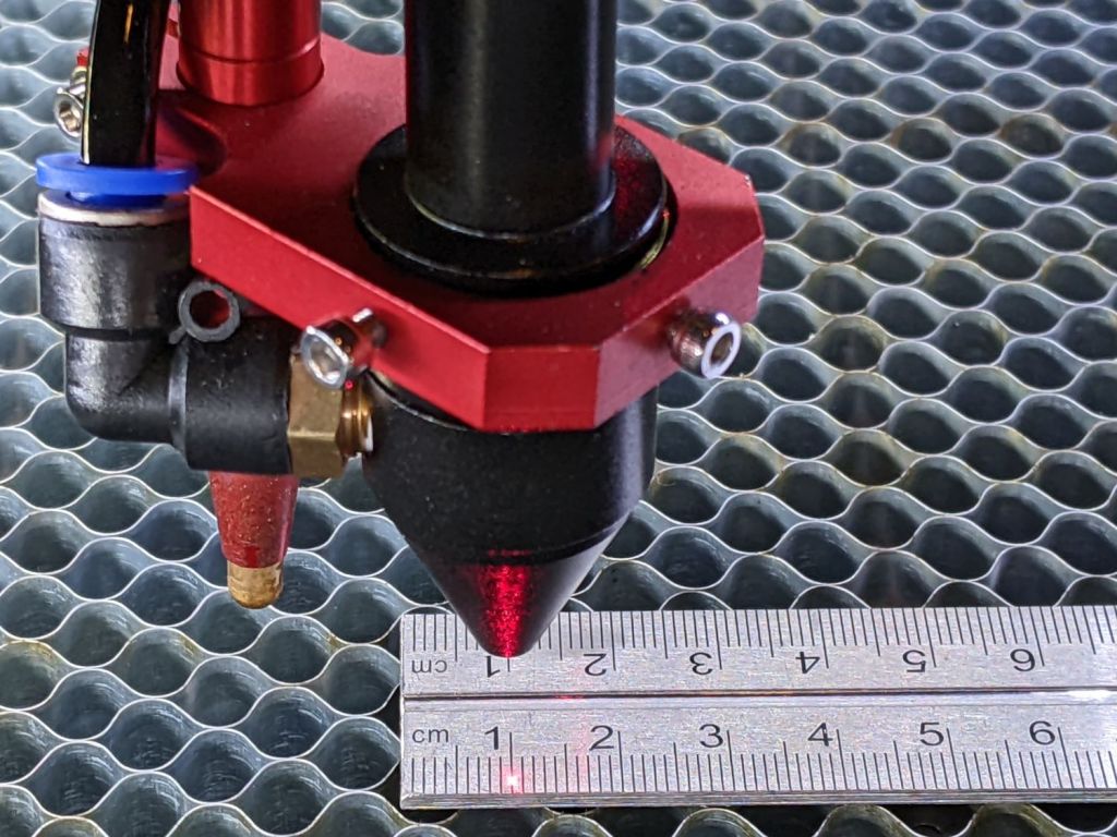
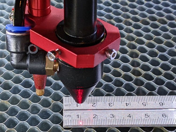
Laying out my longest engraved scale on the honeycomb:
OMTech Axis Cal – dot positioning
The zero-th step aligns the scale with the axis travel: slide one end of the scale to put the dot on the edge, jog to the other end, slide to put the dot on the edge, iterate until the dot is the same brightness on both ends.
The scale lines are a tidy 0.2 mm wide, the red laser dot might be 0.4 (it’s rectangular-ish), and a jog increment of 0.2 mm works well. I can manually align (pronounced “slide”) the scale on the honeycomb to center the dot within a line, whereupon moving the head a known distance to the other end of the scale and counting-while-jogging a few steps until the dot drops into the proper line gives the offset from the correct distance.
Jogging 590 mm along the X axis produced 589.8 mm of actual travel (one jog step short of the line 590 mm from the start), an error of -340 ppm.
Jogging 495 mm along the Y axis travels 494.4 mm, an error of 1212 ppm. That’s considerably more than I expected and required a few iterations until I believed it.
Both axes use steppers with 20 tooth pulleys and 3 mm pitch belts, so the laser head moves 60 mm per motor revolution. The stepper drivers are configured for 5000 steps/rev, so the axes should have a step length of 12 µm = 60 mm / 5000 step. Both axes arrived with Step Length values set to weird numbers very close to 12 µm, but, after a quick check showed incorrect travel distances, I reset them to 12 µm before making real measurements.
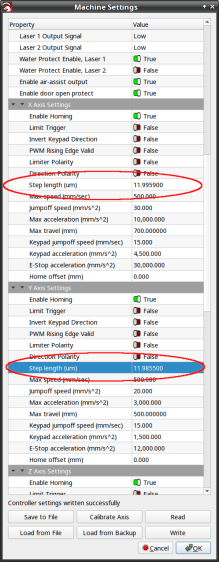
LightBurn provides access to the Ruida controller’s “Vendor Settings” (after a warning to not mess things up) and allows you to change them:
OMTech Laser – Axis step length settings
The values shown above come from multiplying 12 µm by the ratio of the actual to the intended distance:
11.9959 = 12 × 589.8 / 590
11.9855 = 12 × 494.4 / 495
Repeating the tests with those slightly smaller step sizes produces motions that are spot on to within my ability to measure them.
Neither of those changes was large enough to affect the outcome of cutting the Tek Circuit Computer decks, which are much smaller than the full extent of the axes and thus see much smaller errors.
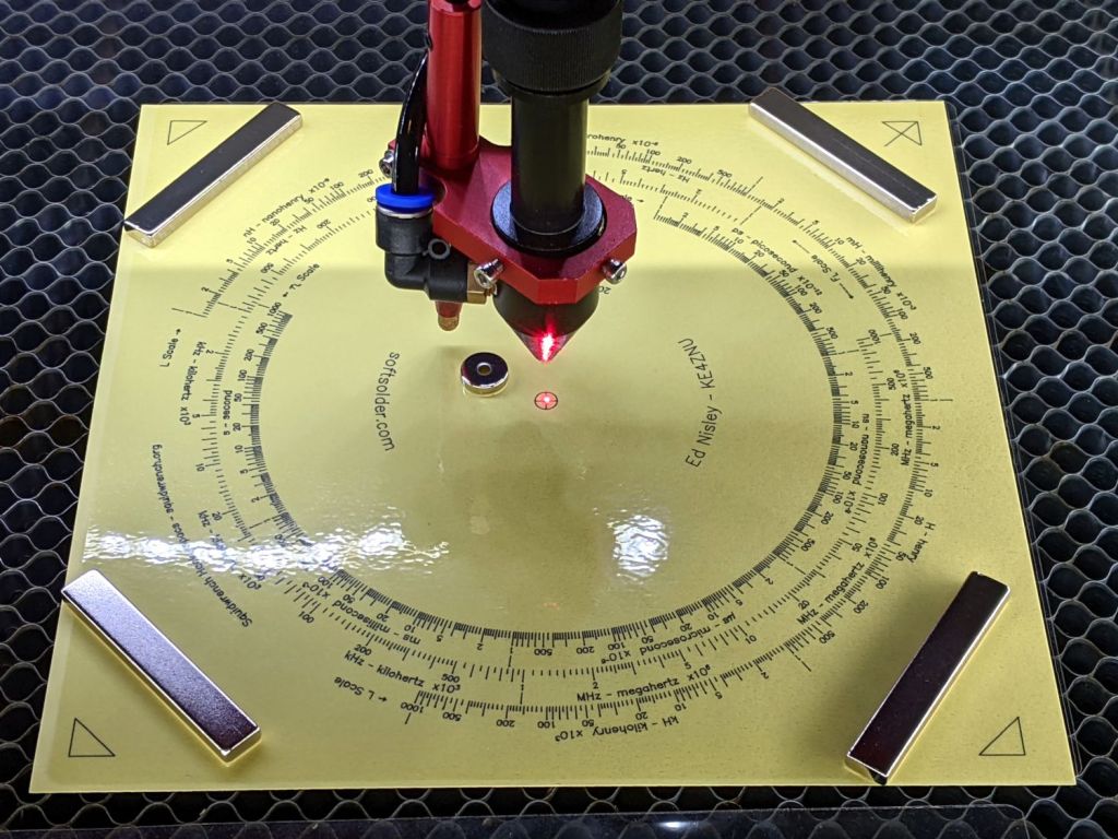
The setup for cutting the Tektronix Circuit Computer decks looks like this:
Tek CC – Bottom Deck cutting setup
Four neodymium bar magnets hold the corners flat against the honeycomb and the neo disk magnet pins the center down, thus ensuring the red alignment laser meets the cutting beam at its focal point on the surface.
The triangular shapes mark the OD of the perimeter (177.8 mm) plus twice the cut margin on each side (2×2 mm), with the tick mark in the upper right ensuring I slap every deck down in the proper orientation. Aligning the two right marks to the edge of the honeycomb frame (with a straightedge for some offset) aims the deck’s 0° index along the cutter’s X axis.
The cut pattern origin is, naturally enough, the center point of the deck, so aligning the red dot to the center cross should put the OD cut at the place all around the perimeter. For confirmation, I fire the laser (“A single ping, Comrade.”) and verify the hole is in the middle of the cross.
Before cutting the deck, the laser also marks the corner shapes, so this may come as some surprise:
Tek CC Middle Deck Corner Targets
The laser printer (a venerable HP LaserJet 1200) produced the dark triangles and the laser cutter (a new OMTech 60 W) burned the light brown marks. The picture is a composite of the four corners, with the blank center removed to concentrate on what’s important.
The scrawls give the edge-to-edge distances in both inches (because that was the scale at hand) and converted to millimeters (because that’s how it’s laid out), with the L suffix for the laser marks.
What’s of interest is that you can’t overlay the two sets of marks by a combination of scaling and rotation with the centers (not shown) of the two patterns pinned together.
The laser measurements differ from the ideal 181.8 mm by 0.1 mm vertically and 0.4 mm horizontally. This may require dinking with the scale factors in the firmware, which I recall having weird values.
The LaserJet is definitely not a precise instrument, off by 0.4 mm vertically and a millimeter horizontally, with considerable variation. I think this comes down to unrealistic expectations for toner stuck to a flexible sheet wrapped around rollers and heated enough to melt dust into the fibers.
I suppose we’re even, because I have no recollection of setting a Purchase Reminder on anything at any time.
By default, my email client does not display remote content in messages, which chops out the cute pictures, as well as killing all the cruft and tracking widgetry infesting commercial email these days.
The Dell Optiplex 9010 acting as a file server woke up dead after I plugged it in after returning from a road trip. Its ID sticker shows a manufacturing date almost exactly nine years ago and the problem was exactly what you might expect:
Optiplex CR2032
I’d never measured 100 mV on a CR2032 before.
Because the Optiplex runs headless in the basement, diagnosis required hauling it upstairs, booting it with a display & keyboard, whacking the date into the current decade, then resetting a few other vital bits.