Over the last several weeks the taillight on Mary’s Tour Easy became dim. I verified the LED had failed by soldering the taillight driver to a different 1 W LED stuck on a separate heatsink, whereupon the LED lit up as it should.
Testing the failed LED with a bench power supply clipped to its wires showed it passed only 15 mA, even with 6 V applied directly to the wires. Those 1 W LEDs normally drop 2 V at 400 mA, so something was definitely wrong in there.
Which meant I had to build another taillight, as described yesterday, and reuse the original electronics and PVC tube. After mounting the new taillight on Mary’s bike, I could autopsy the failed LED.
Because everything is glued into the heatsink, the first step is cutting it apart to free the LED:
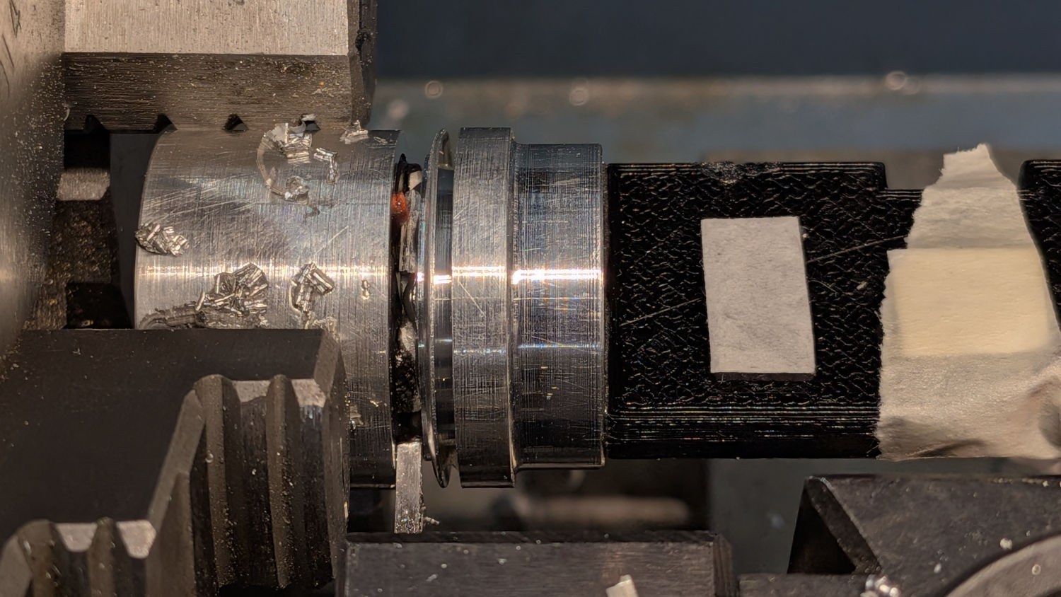
I stopped the first cut when it just kissed the two wire holes, moved over a little more than the width of the cutoff tool, and tried again. Second time was the charm and I now have a clean aluminum tube that ought to come in handy for something, sometime.
Concerted prying under the edge of the LED PCB popped it off the heatsink:
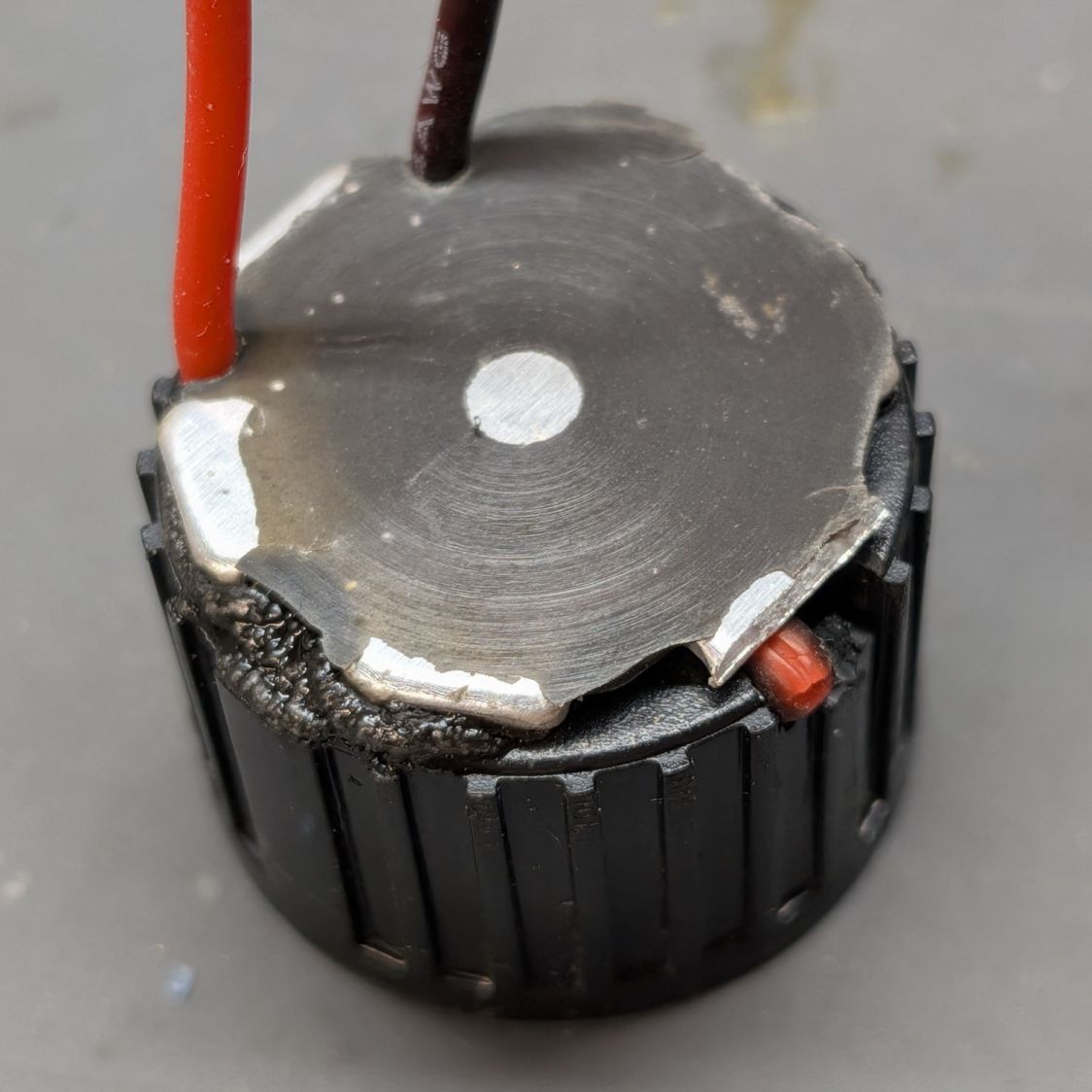
The red wire sticking out on the right shows a little damage from the cutoff tool, which also chipped the epoxy while bending the aluminum LED base. The bare spot in the middle matches the screw hole in the heatsink, with the rest remaining firmly bonded, so the epoxy was doing its job.
Prying the LED off the lens holder:
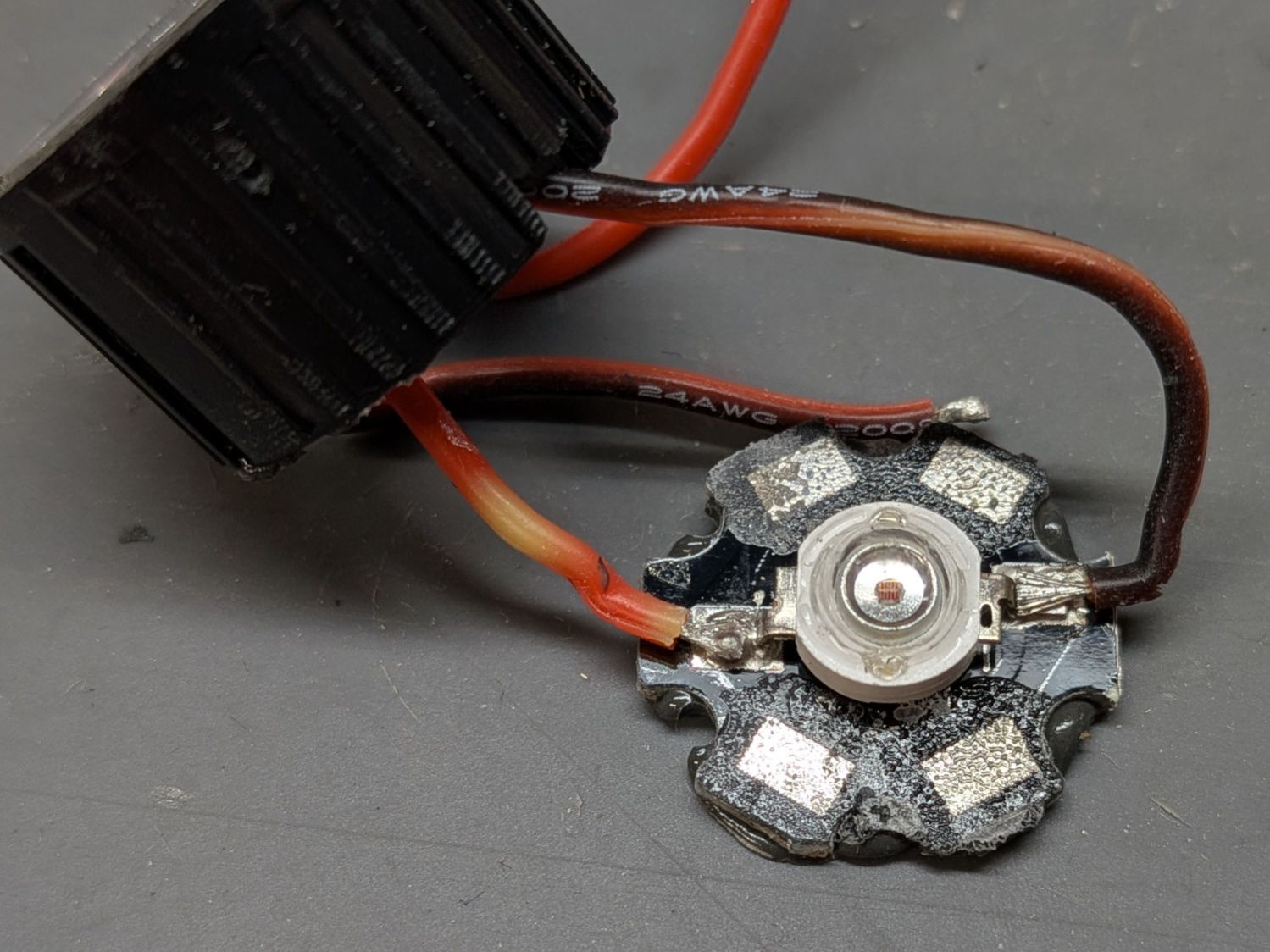
If I didn’t know better, I’d say the red silicone insulation was sun-faded, but for sure no sun gets inside the lens holder.
An ohmmeter showed both wires had good continuity to their LED pads, which were firmly soldered to the PCB pads; the pads don’t carry any current in this setup. I then hitched up the bench supply to the wires again:
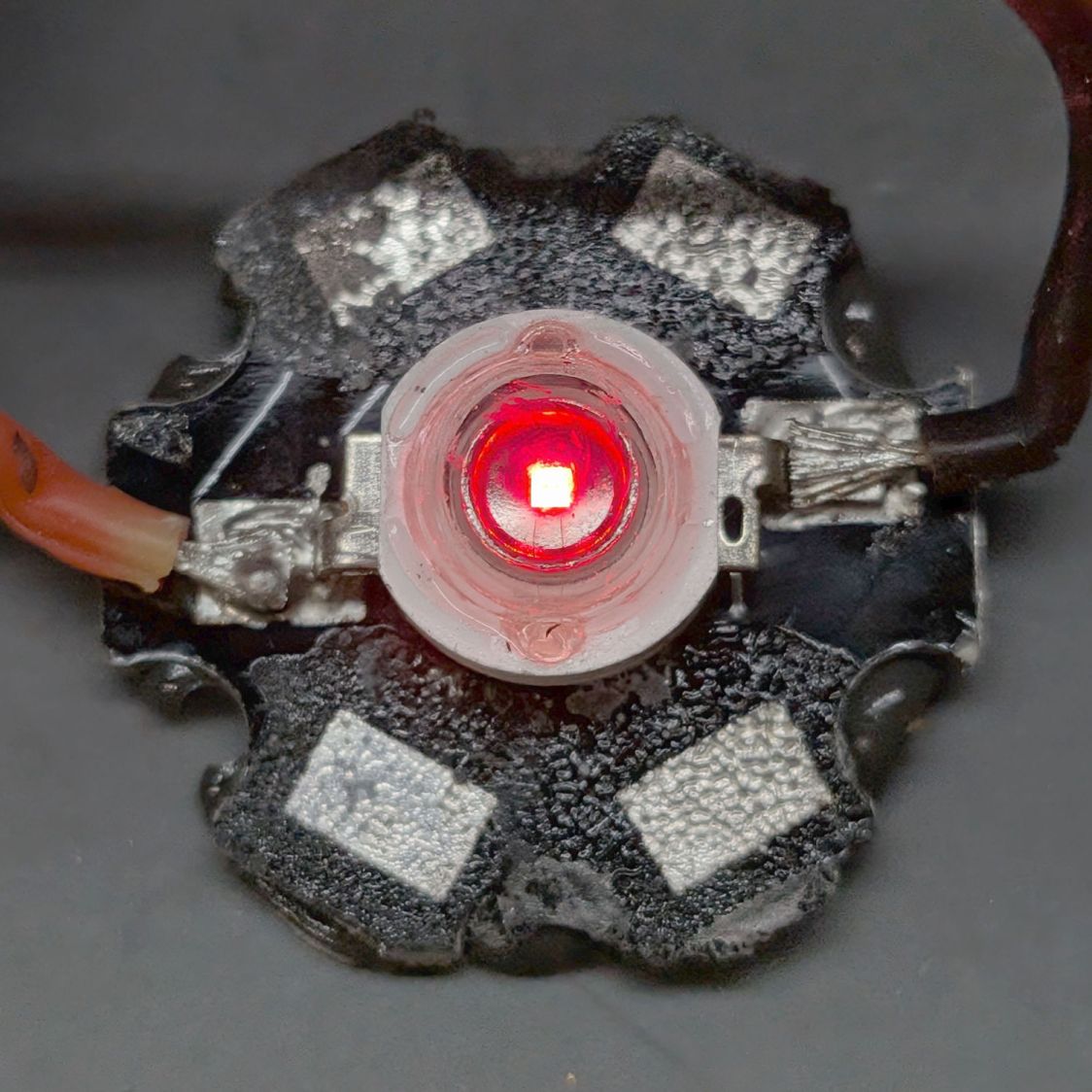
Whereupon the LED glowed brightly and some quick testing (because it’s not on a heatsink) with the bench supply in constant-current mode showed it once again drew about 400 mA with 2 V applied and glowed brilliantly as it should.
I had previously removed the reflowed solder from the PCB thermal pad and added thermal paste before resoldering the LED:
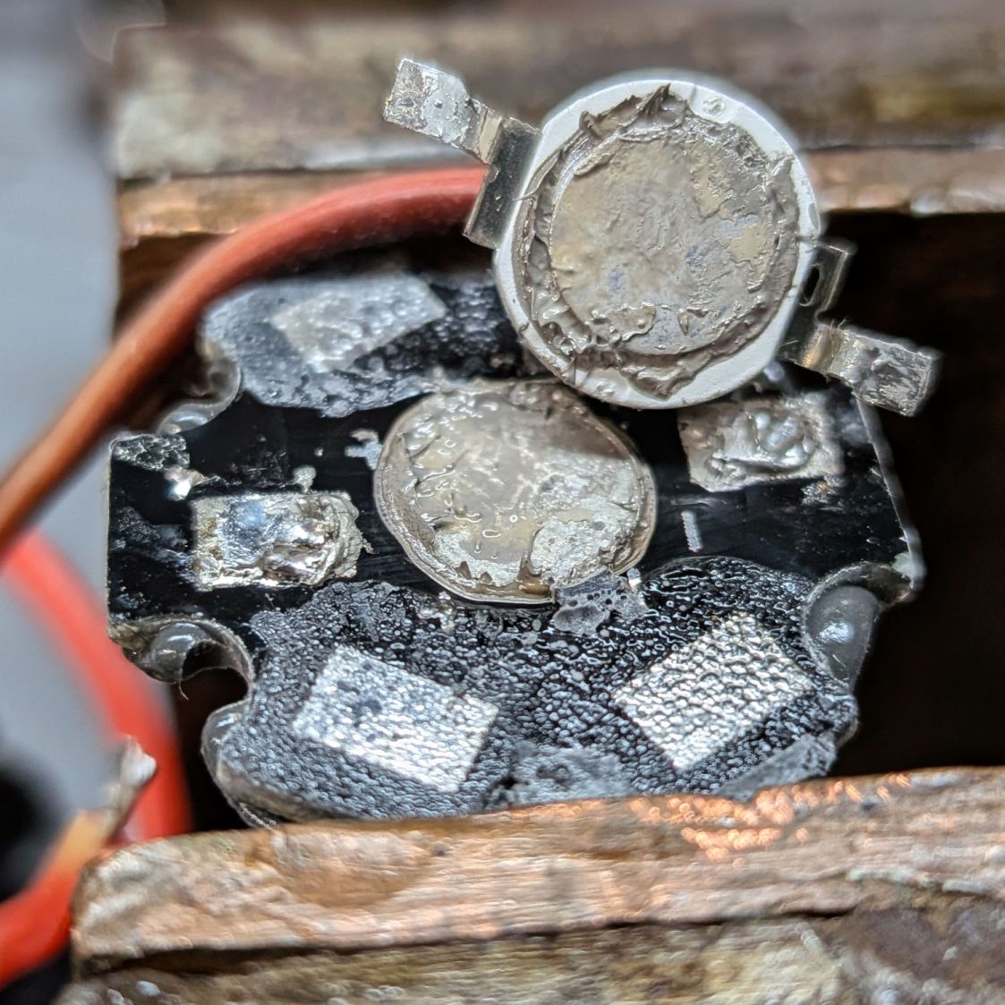
So I have no idea what caused the original failure, how the LED could survive with 6 V applied to its terminals, or what would have caused it to recover. It now has a “?” scrawled on the PCB for future reference.
The world is full of mysteries …


Spam comments get trashed, so don’t bother; you’re not as clever as you think. Comment moderation may cause a delay.