The 1 W red LED in the taillight on Mary’s Tour Easy failed and, because the LED is epoxied into the heatsink forming the business end of the light, I had to machine a replacement. This proceeds much as before, with some improvements & simplifications.
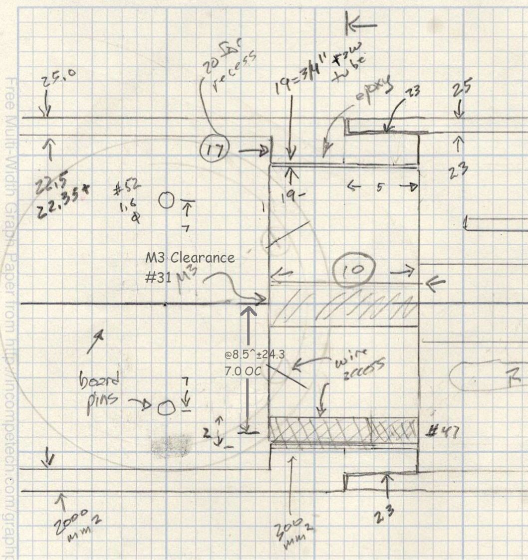
A revised sketch of the key dimensions shows a clearance hole for the 3 mm screw (to eliminate tapping the heatsink) and a reminder about how to locate the wire holes:
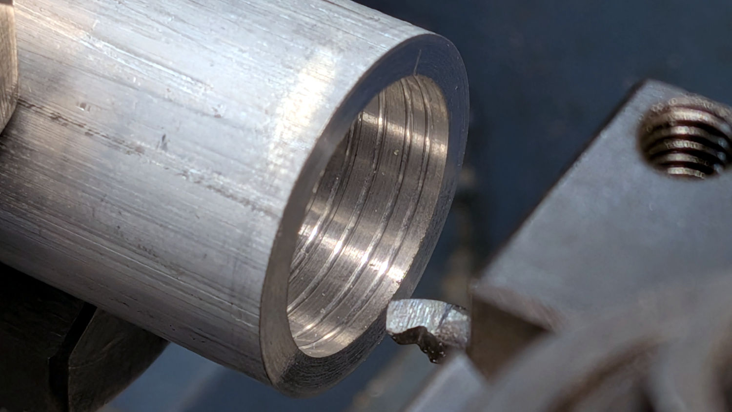
Bore a 19 mm ID recess 10 mm deep in the (1 inch OD × ¾ inch ID) aluminum tube and score the ID for improved epoxy griptivity:
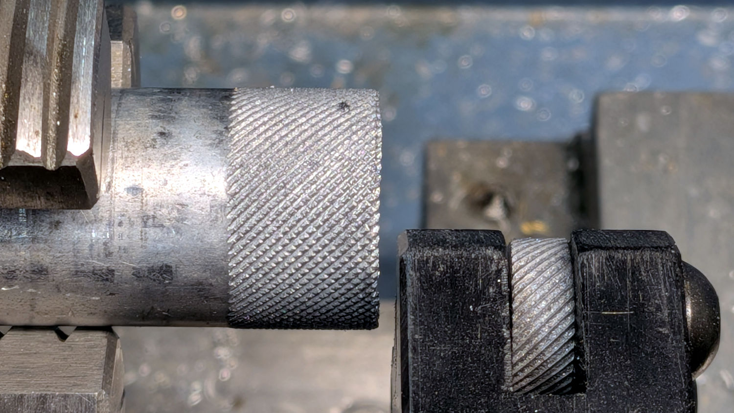
Knurl the ¾ inch rod to bring the OD to a slip fit in the shell:
Take them ouside, hose down with brake cleaner to get rid of the cutting fluid, butter ’em up with epoxy, align in the lathe, and let ’em cure overnight:
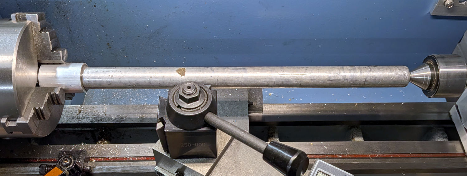
This time I managed to not cut off the rod, which dramatically simplifies boring the shell and facing the front end of the rod flush with the inside of the shell so the LED PCB sits flat in there:
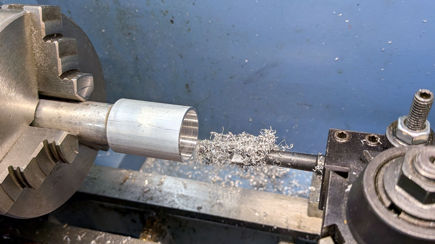
Clean up the shell OD and turn the back to 23 mm OD to fit the PVC tube from the failed taillight:
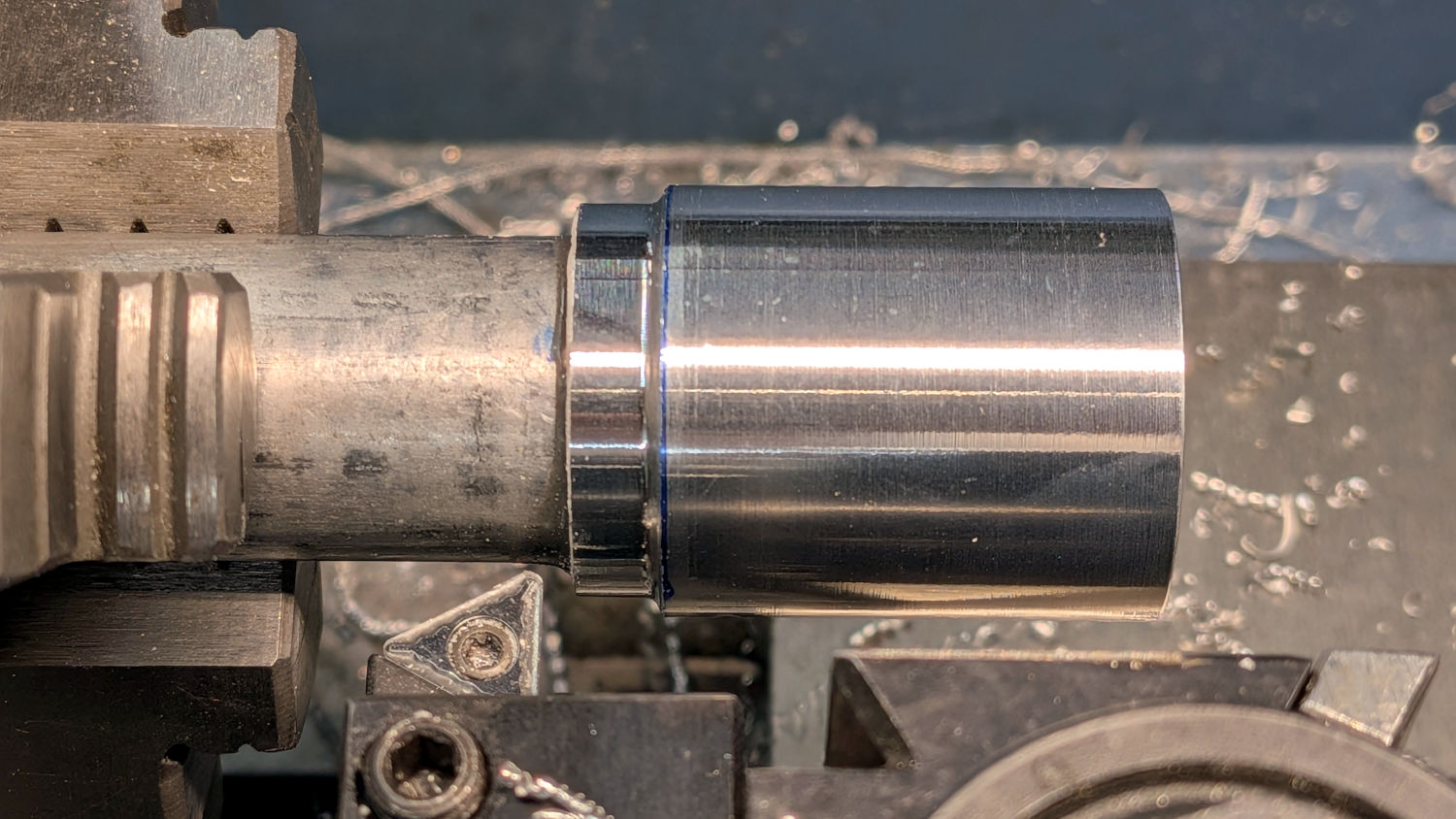
Crisp up the edge for a tidy fit:
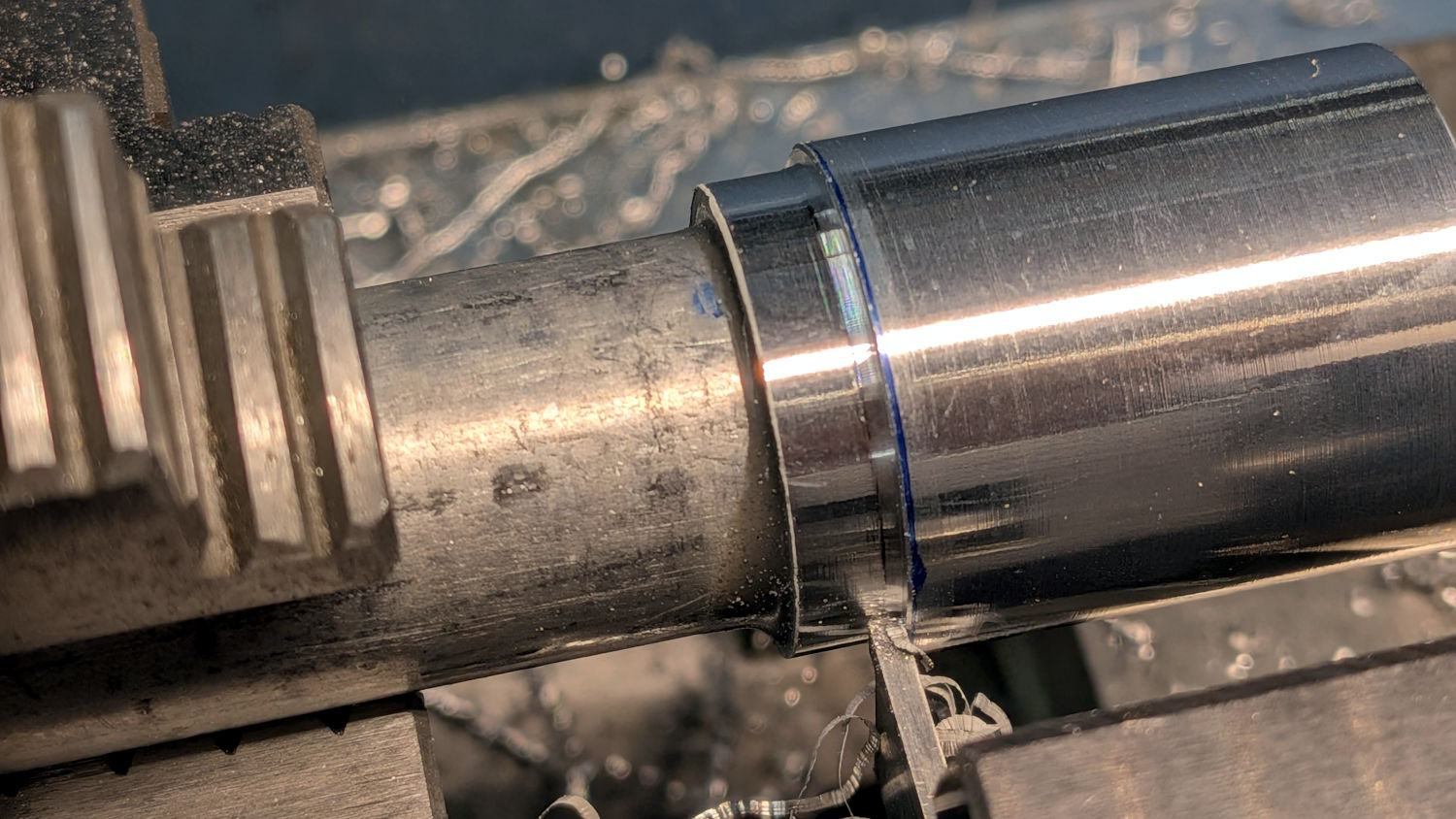
Break / file all the corners, then bandsaw the rod and face the back end:
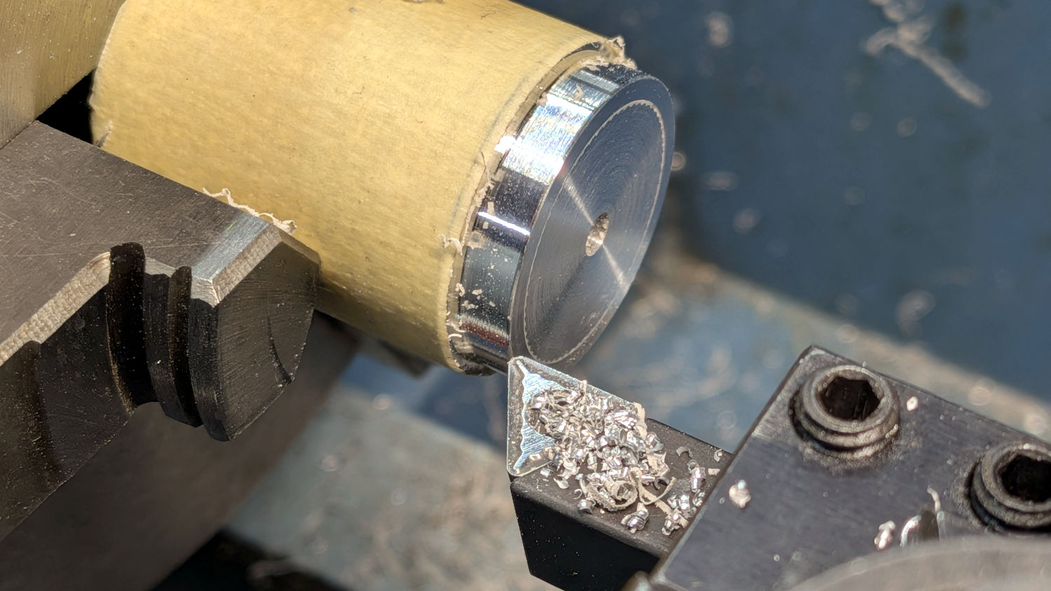
Set it up on the Sherline mill, find the center, and use manual jogging to poke the holes at the proper coordinates:
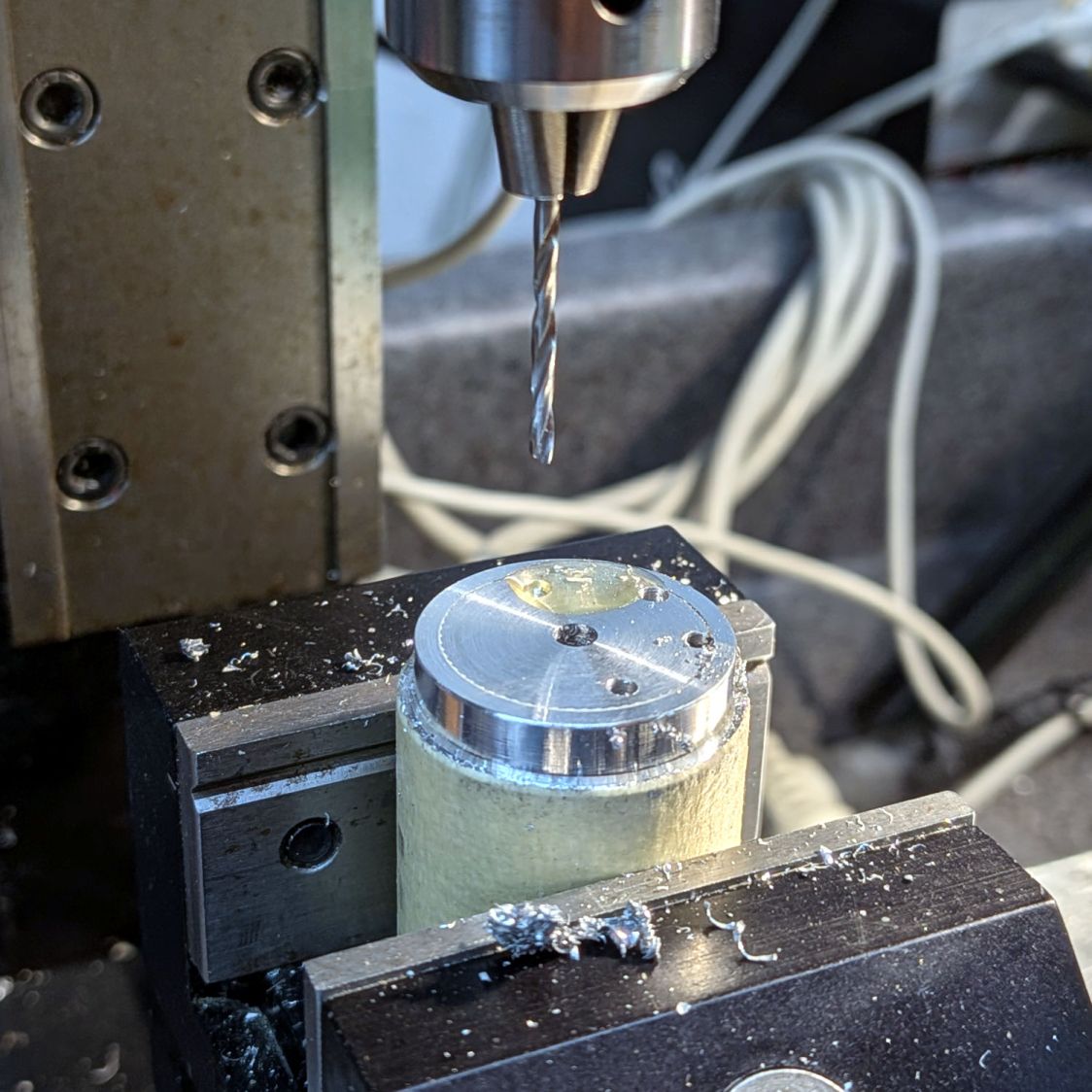
Take the finished heatsink outside again for more brake cleaner action.
The 3D printed circuit plate now sports two inserts:
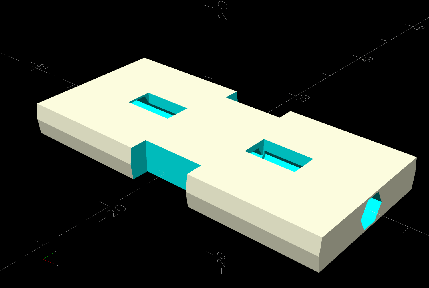
Epoxy the inserts in place, prepare two 1.6 mm = 1/16 inch steel wires, and chop the head off an M3 screw:
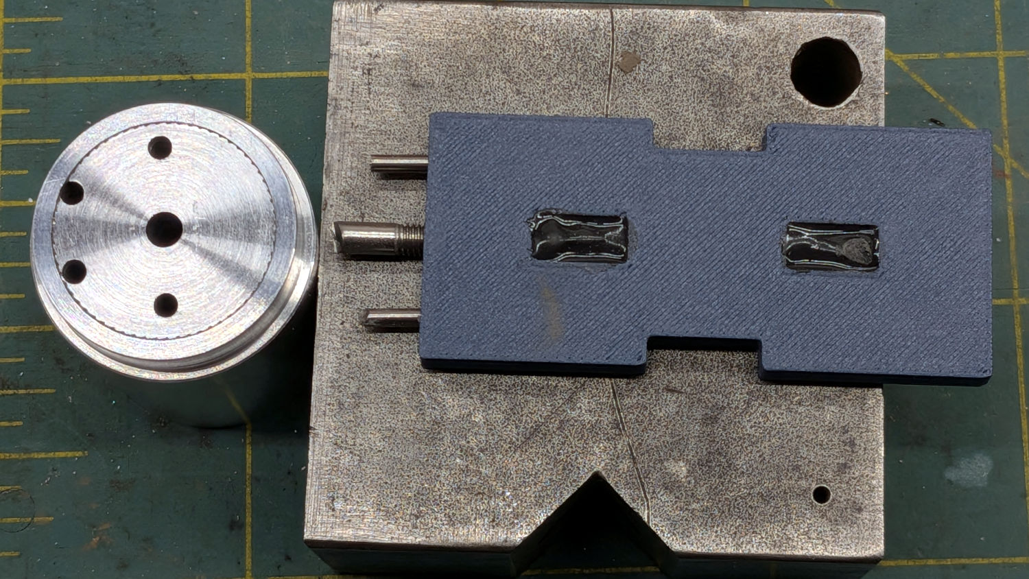
Stipulated: my center-finding hand is weak.
Aligning the LED heatsink with those wire holes is a pain:
- Clean up the 1 W LED PCB
- Solder the LED in place atop some heatsink compound
- Push the lens holder (without the lens!) over the LED
- Insert holder + LED into the heatsink
- Rotate to put one LED terminal between the wire holes in the heatsink
- Rotate to align the recesses in the PCB with the wire holes in the heatsink
- Match-mark the holes on the lens holder with a transfer punch
- Grab the holder in the Sherline vise
- Align & drill wire holes in the holder
- Solder wires to the LED PCB, aimed inward atop the LED leads
With the LED & lens holder prepared & set aside, butter the circuit plate parts with JB PlasticBonder, align the plate perpendicular to the heatsink using V-blocks / 123 blocks / whatever, and let it cure overnight.
The lens allows plenty of room to run the wires from the PCB around the LED inside the holder to the holes:
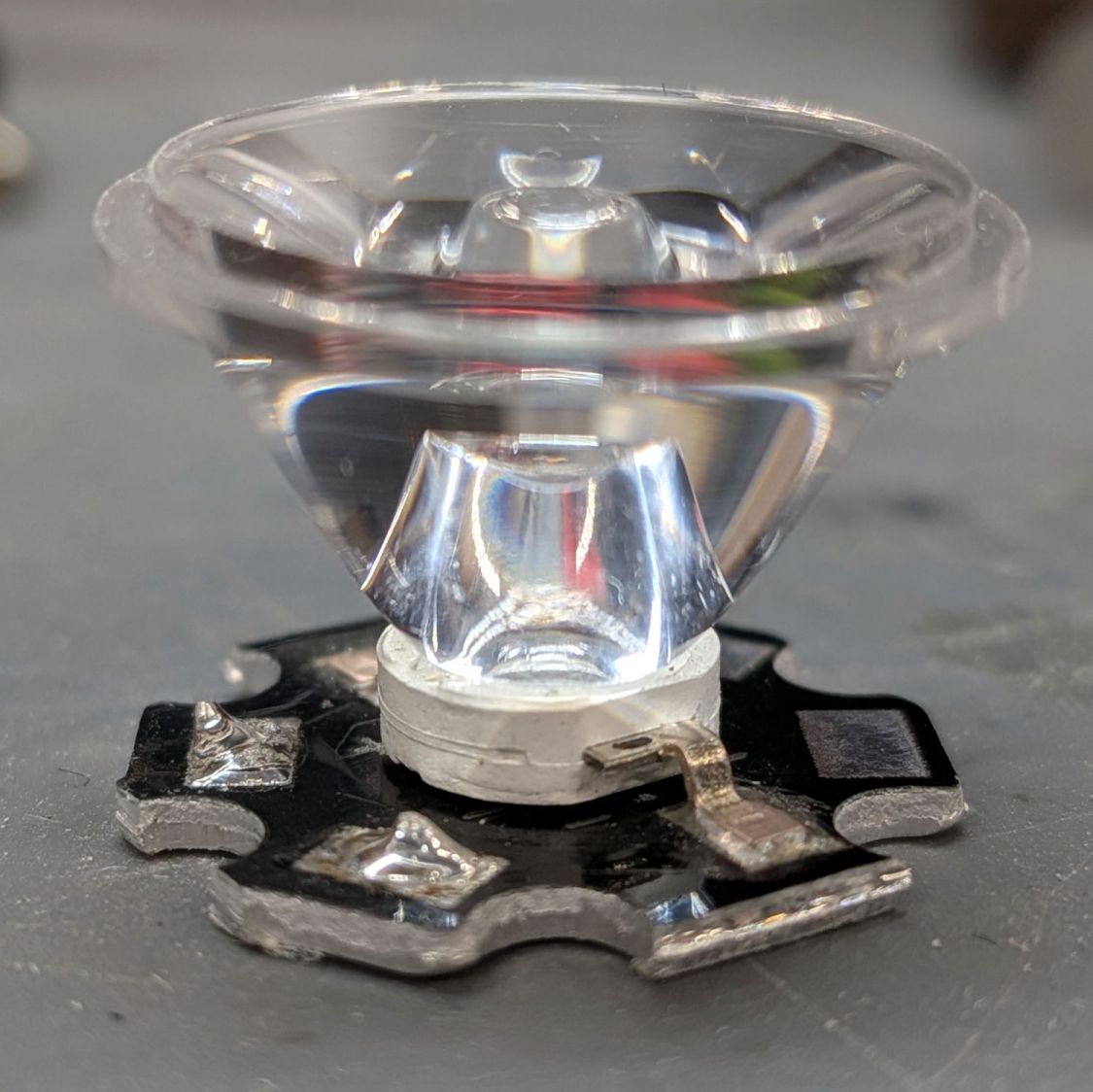
So do that:
- Dab PlasticBonder on the bottom of the lens holder
- Stick the LED to the holder (still with no lens!)
- Thread the LED wires through the holes in the holder, the LED PCB, and into the heatsink
- Dab PlasticBonder on the bottom of the PCB
- Ease the holder + LED into the heatsink while pulling the wires through the holes
- Finally install the lens in the holder
- Clamp the whole mess lenthwise with padding atop the lens to prevent scratches
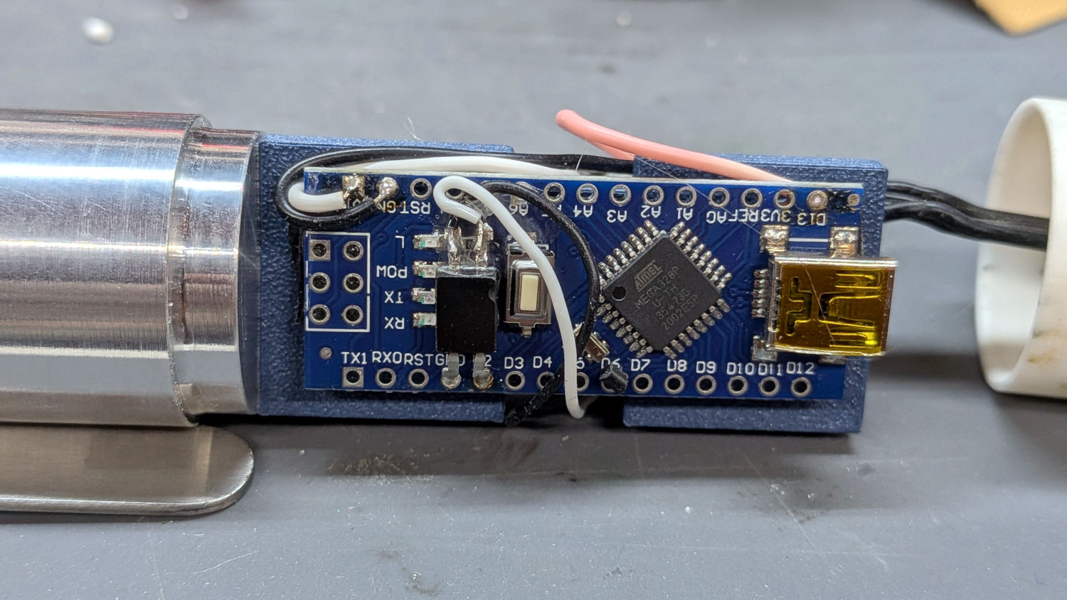
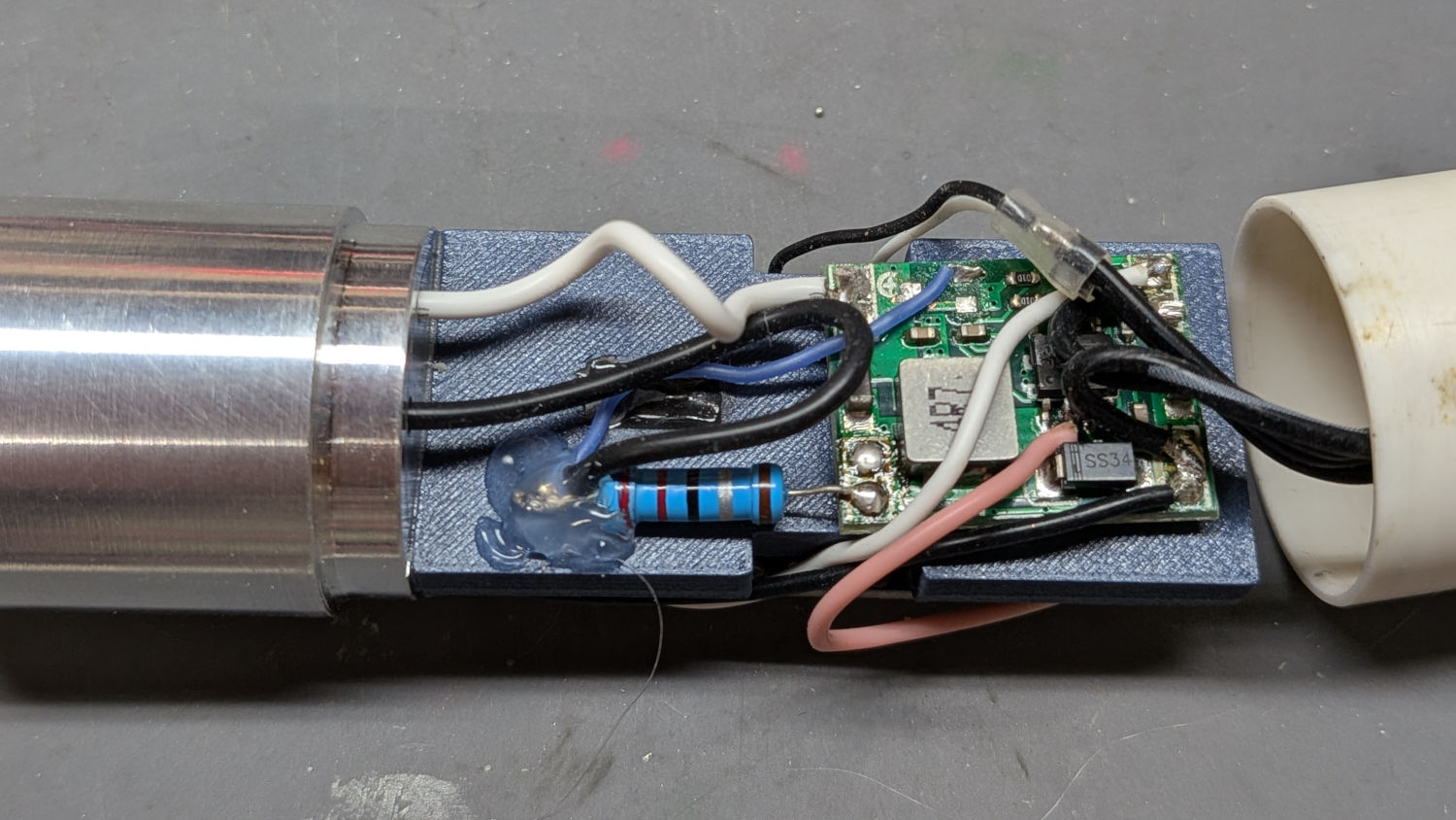
I transferred the circuitry from the failed taillight to the new one, atop refreshed double-sided foam tape:
With hot-melt glue securing the 2 Ω current-sense resistor to the circuit plate:
Slide the PVC case over the circuit plate, secure the end cap with a 25 mm screw, and reinstall on the bike:
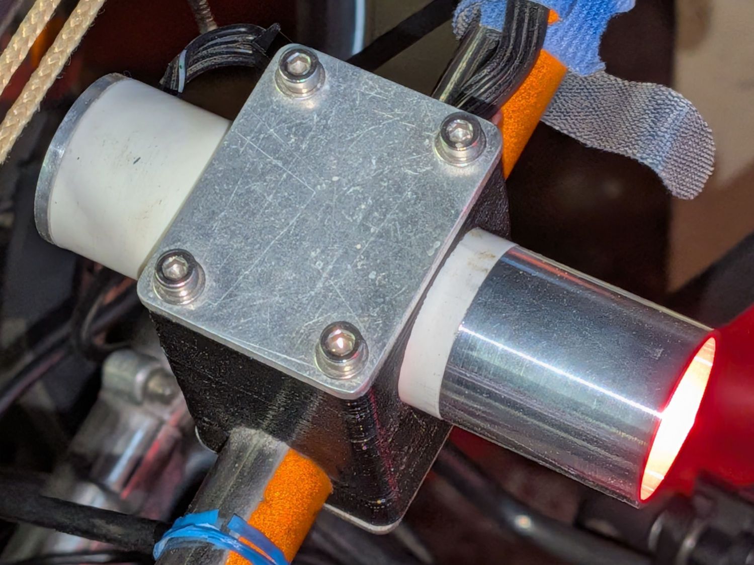
It’s angled 1° up from horizontal:
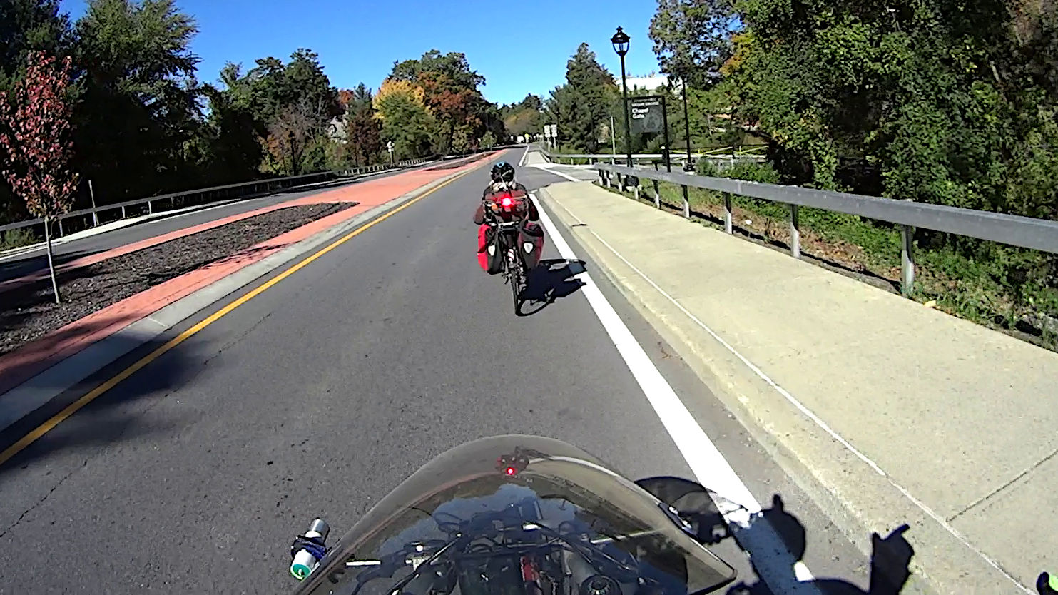
Wow, is that thing bright!


Spam comments get trashed, so don’t bother; you’re not as clever as you think. Comment moderation may cause a delay.