Having discovered the need for careful alignment of the LED PCB with the lens, I paid more attention to detail this time around.
The LEDs arrive soldered to PCBs atop aluminum star heat spreaders, but the one I picked out of the bag looked slightly misaligned. Unsoldering it showed a smear of solder paste had melted across the central pad:
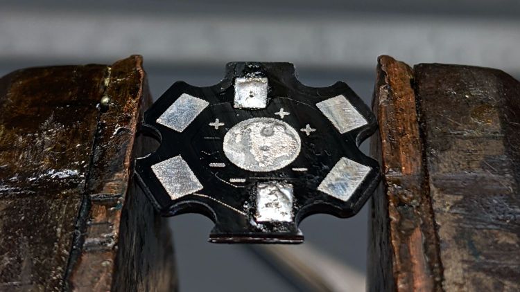
The LED has a die contact slug on the bottom which, I suppose, could be directly soldered to the spreader. For my simple needs, removing the errant solder, plunking the LED atop a layer of heatsink compound, and resoldering the leads should suffice:
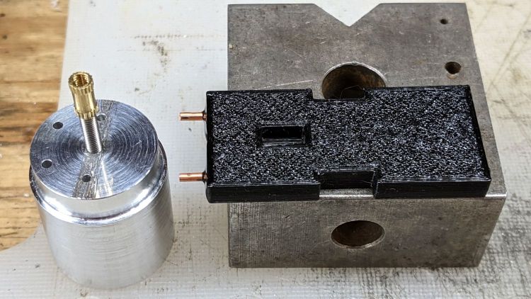
The LED holder has a pair of slots aligning it with the LED leads on the PCB. The base of the holder sits flush against the PCB, so the wires must attach directly to the LED pads.
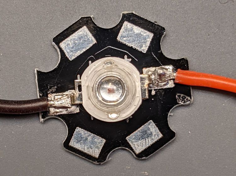
I ran the wires for the amber light through holes close to the pads:
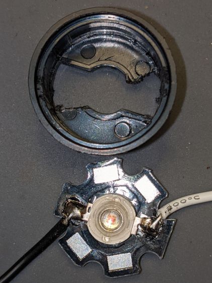
Which required chewing two passages in the base of the holder:
It turns out the 5° and 10° lenses are strongly conical and leave plenty of room around the LED to run a wire around the inside of the holder, so I drilled a pair of holes to put both wires on the same side of the circuit plate:
The holder required minor surgery to let the wire double back on itself over the LED pad:
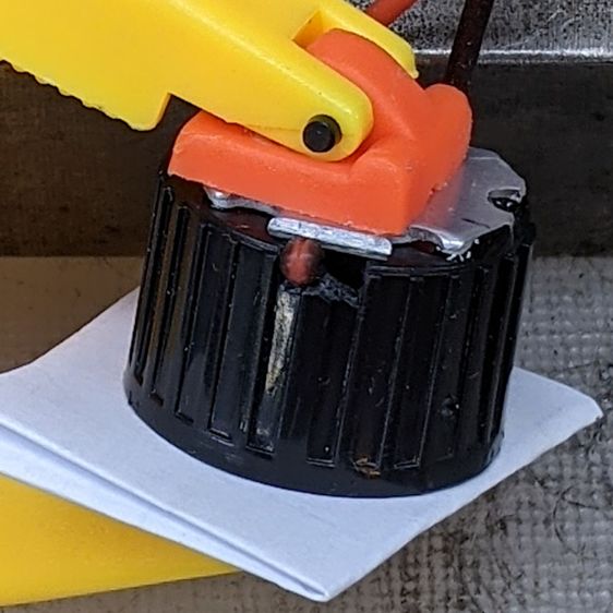
The wires thread through two holes drilled in the plastic holder:
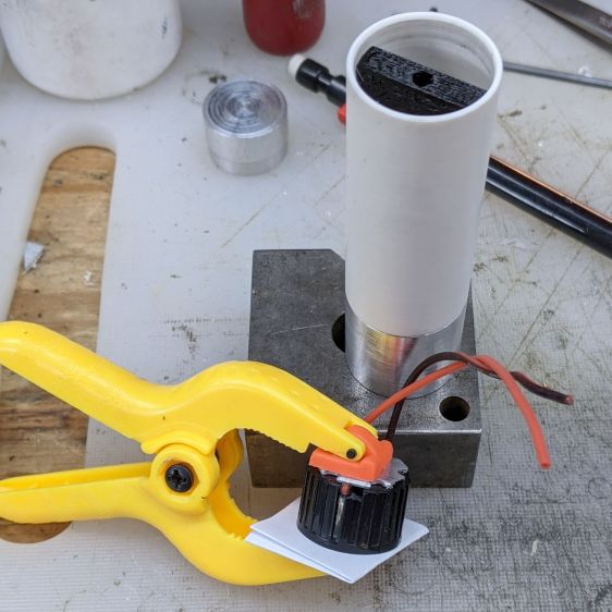
More urethane adhesive glues the PCB to the LED holder, with the clamp applying pressure to the lens to ensure the lens seats properly around the LED. It turned out that worked well and the light has a nicely rounded beam.
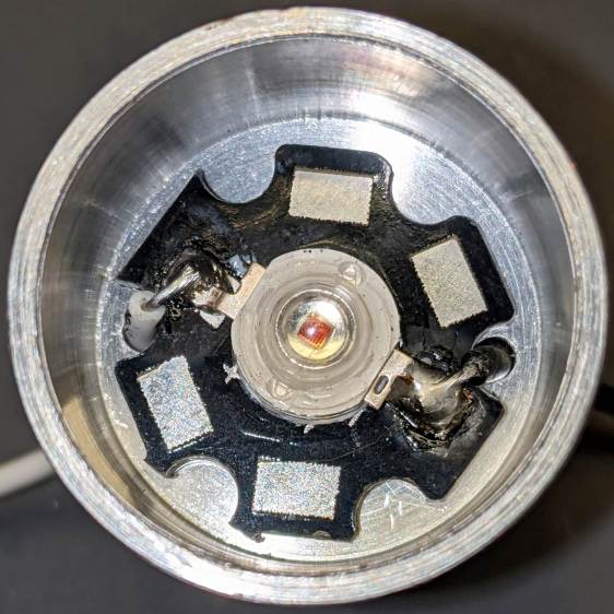
With the optics bonded together, metal-filled JB Weld epoxy attaches the heat spreader to the heatsink with good thermal conductivity:
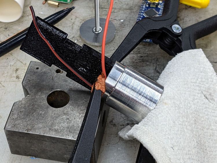
The LED holder is a slide fit in the heatsink, so the clamps can keep the PCB flat on the bottom of the recess while the epoxy gets a good grip on all parts.
Now it’s just a matter of wiring everything up!
