Ruida laser controllers do not allow the platform to rise above the U=0 origin set by the autofocus pen = switch. While this isn’t a problem for flat surfaces, focusing on the exact top of a horizontal cylinder, particularly a small rod, may be overly difficult.
So a focusing pad seems like a Good Idea™:
The general idea:
- Align a flat horizontal surface with the rotary chuck’s axis
- Do the autofocus operation with a well-defined landing zone under the pen
- The
Focus Distanceputs the laser head at the proper height for a focused spot on the pad - Jogging the head upward (= platform downward) by the workpiece radius puts the focused spot exactly at the right height
- Remove the focus pad
- Install the workpiece
- Fire The Laser
The solid model:

Features of note:
- The chuck jaws fit into the recesses on the left end for a firm grip with good alignment
- The lengthwise notch lies on the rotary axis parallel to the laser’s X axis
- The crosswise notch is juuust rightward of the chuck jaws, marking the leftmost end of whatever you’re engraving
Because I added a home switch to the Ortur YRC-1 case, Jaw 1 automagically ends up on top after homing, thus automagically making the focus pad horizontal. Getting that right required fine-tuning the rotary’s home switch trip point, which turned out to be easier to do using the Home Offset configuration value after I replaced the cam I thought would work:
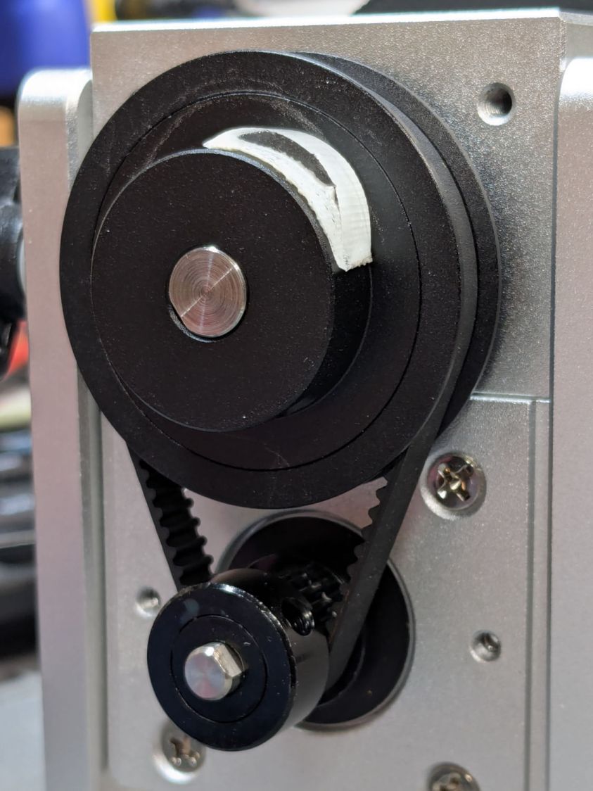
Instead, a simple M4 setscrew (standing proud of the pulley surface in one of the tapped holes for the real setscrew securing the pulley to the shaft) trips the switch much more repeatably :
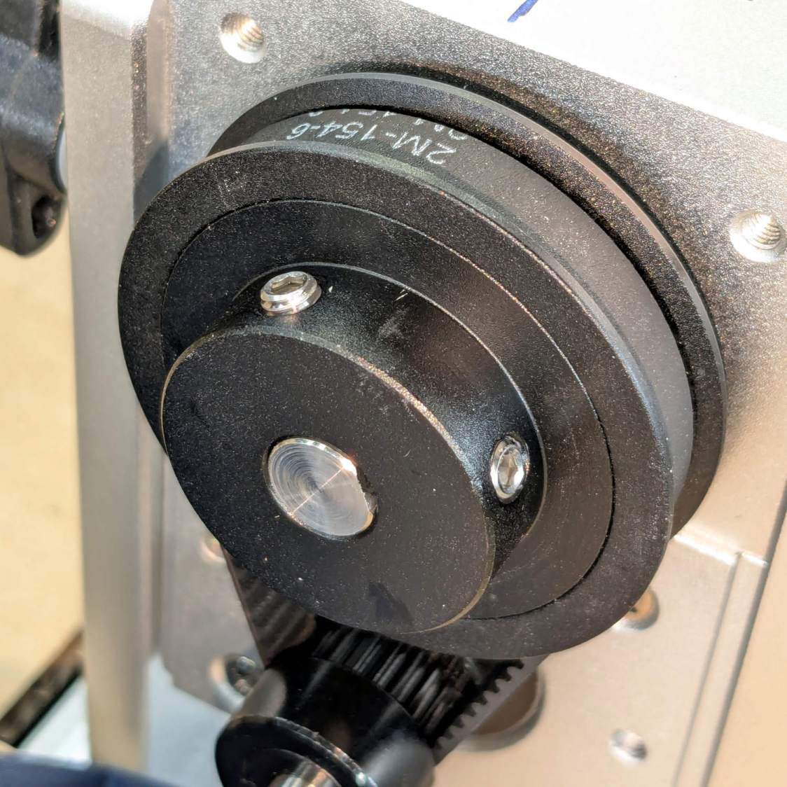
The setscrew on the right sits flush with the surface to prevent the switch roller from falling into the hole. The real setscrew underneath it locks the pulley to the shaft’s flat.
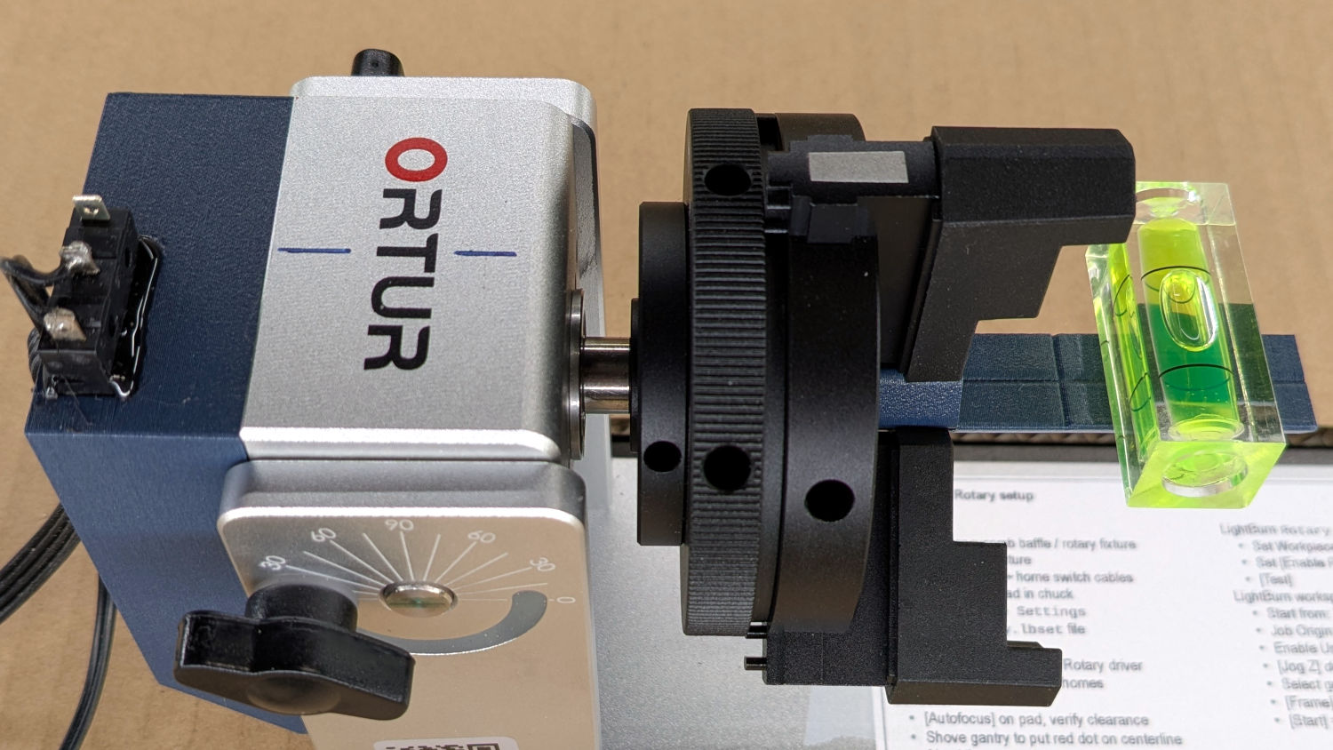
With that in place, a quick binary search settled on a Y axis Home Offset = 1.75 mm to put the pad level with the top of the rotary’s case, which is Level Enough™ due to my tweaking the machine’s foot elevations after jacking the whole machine up on risers:
The Home Offset value:
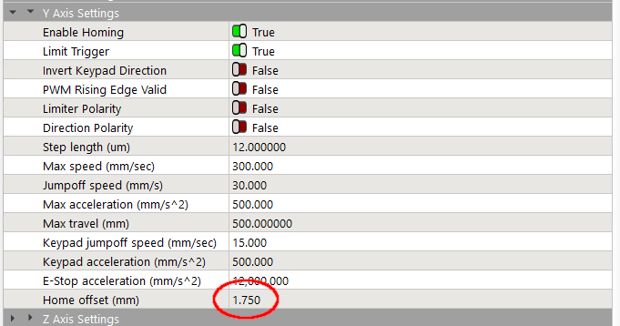
The speed and acceleration values are much lower than used with the linear Y axis, because apparently Ruida computes the corresponding step values using the workpiece diameter in the Rotary section. Small diameters produce impossibly fast motions, which suggests they expect you to set the optimum values based on back-calculations from the object diameter; ain’t nobody got time for that.
Anyhow.
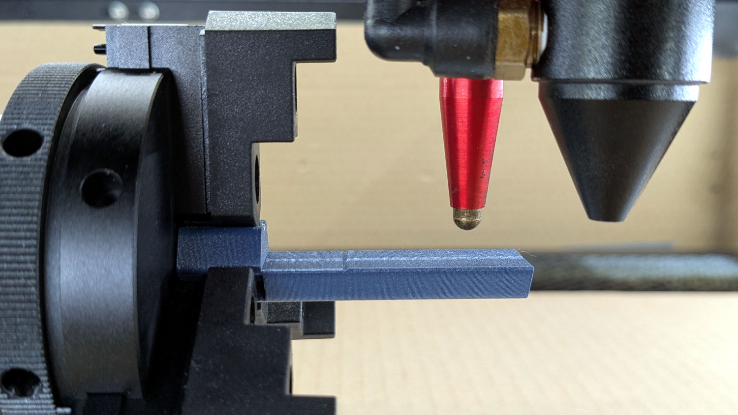
After autofocusing, the red-dot pointer now indicates the laser spot position, so jog the X axis and drag the gantry to put the spot on the axis mark:
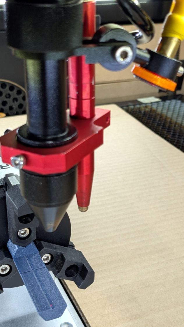
The orange rim on the red-dot pointer cuts down the beam intensity to make a smaller dot and provides easier position tweaks.
Then jog the X axis to put the dot at the transverse mark just beyond the chuck jaws:
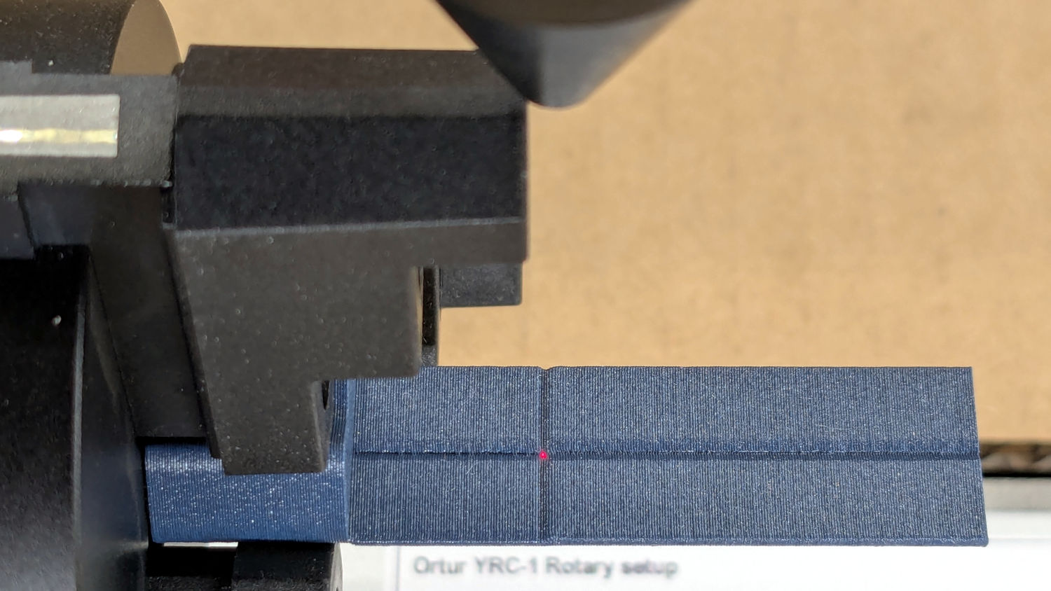
Hit the Ruida Origin button to set that as the user origin, so you can reference the LightBurn design to the hardware position.
Move the platform down by the workpiece radius, jog the nozzle along the X axis to get it out of the way, remove the focus pad, install the workpiece, and you’re good to go. The checklist visible beyond the bubble level shows it’s not quite that simple, but we’re getting there.
The OpenSCAD source code as a GitHub Gist:
| // Ortur Rotary Focus Pad | |
| // Ed Nisley – KE4ZNU | |
| // 2026-01-04 | |
| include <BOSL2/std.scad> | |
| Style = "Show"; // [Build,Show] | |
| /* [Hidden] */ | |
| ID = 0; | |
| OD = 1; | |
| LENGTH = 2; | |
| HoleWindage = 0.2; | |
| Protrusion = 0.1; | |
| NumSides = 8*3*4; | |
| $fn=NumSides; | |
| // Magic numbers to fit Ortur jaws | |
| PadOAL = 60.0; // clear assist air fitting | |
| PadIR = 7.0; // jaw tip 35 mm above this point | |
| JawOAL = 14.0; // clear large jaws | |
| Reticle = [0.7,0.7,PadOAL]; | |
| OriginOffset = 28.0; // X origin from chuck plate | |
| //—– | |
| // Pad to give autofocus probe a flat landing zone | |
| module FocusPad() { | |
| difference() { | |
| linear_extrude(PadOAL) | |
| hexagon(ir=PadIR,realign=true,rounding=3.0); | |
| up(JawOAL) { | |
| cube(PadOAL,anchor=BOTTOM+LEFT); | |
| cube(Reticle,spin=45,anchor=BOTTOM); | |
| } | |
| up(OriginOffset) | |
| cube(Reticle,spin=45,orient=FRONT,anchor=CENTER); | |
| for (a=[0:120:360]) | |
| rotate(a) | |
| down(Protrusion) | |
| linear_extrude(JawOAL + 2*Protrusion) | |
| right(PadIR + 15 – 2) // eyeball fit | |
| hexagon(or=15,rounding=0.5); | |
| } | |
| } | |
| //—– | |
| // Build things | |
| if (Style == "Show") | |
| yrot(90) | |
| zrot(180) | |
| FocusPad(); | |
| if (Style == "Build") | |
| FocusPad(); | |

Spam comments get trashed, so don’t bother. Comment moderation may cause a delay.