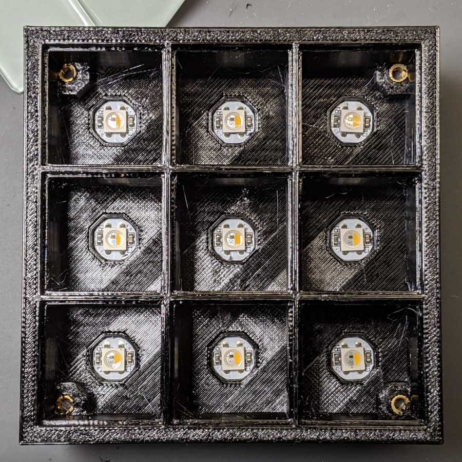
Tweaking the glass tile frame for press-fit SK6812 PCBs in the bottom of the array cells:
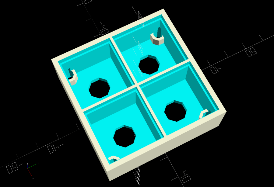
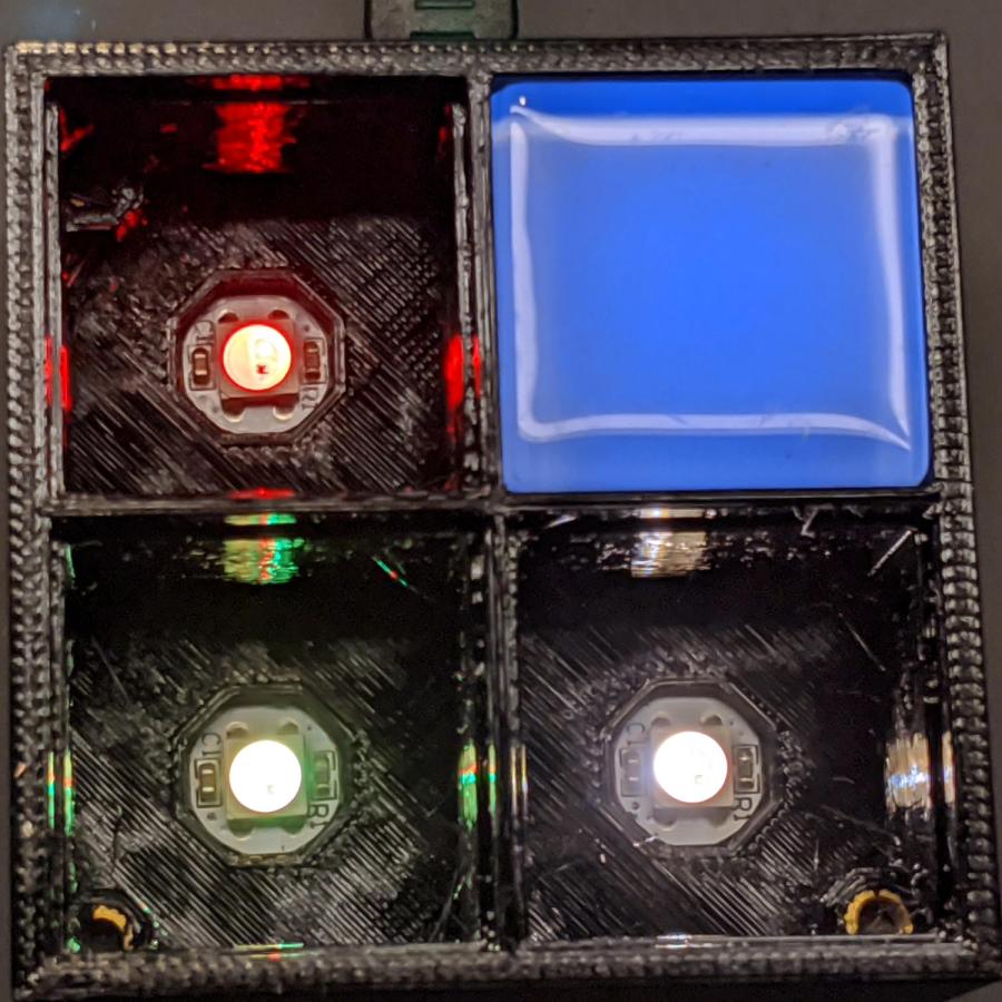
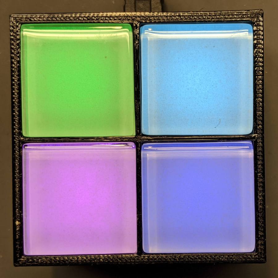
Which looks like this with the LEDs and brass inserts installed:
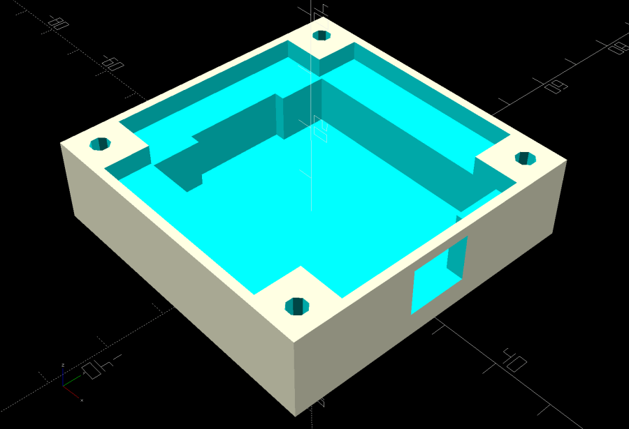
The base holds an Arduino Nano with room for wiring under the cell array:
Which looks like this after it’s all wired up:
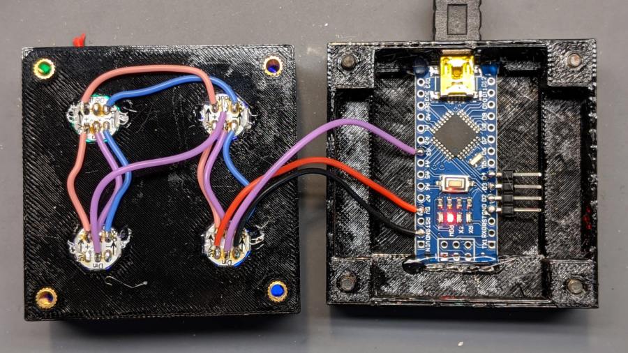
The weird colors showing through the inserts are from the LEDs. The red thing in the upper left is a silicone insulation snippet. Yes, that’s hot-melt glue holding the Arduino Nano in place and preventing the PCBs from getting frisky.
Soak a handful of glass tiles overnight in paint stripper:
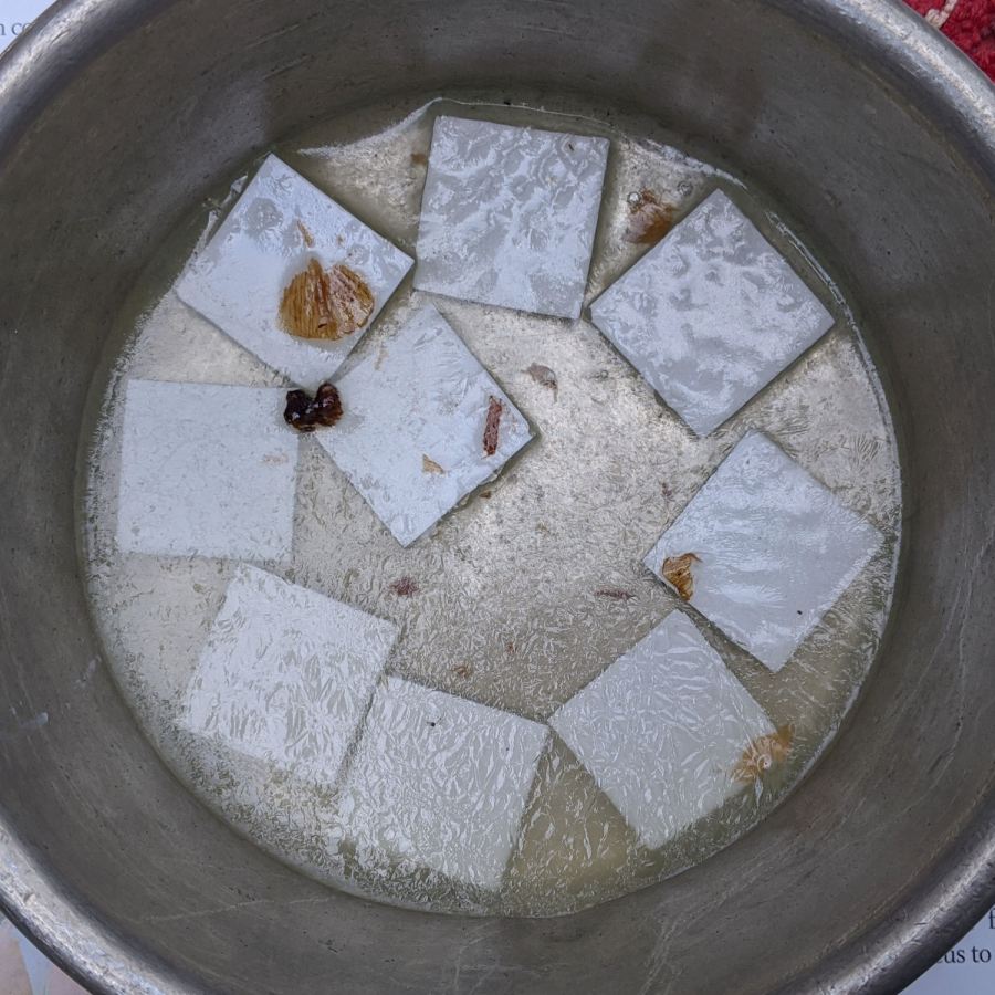
Whereupon the adhesive slides right off with the gentle application of a razor scraper. Rinse carefully, dry thoroughly, and snap into place.
Tighten the four M3 SHCS and it’s all good:
So far, I’ve had two people tell me they don’t know what it is, but they want one:

The OpenSCAD Customizer lets you set the array size:
However, just because you can do something doesn’t mean you should:

Something like this might be interesting:

In round numbers, printing the frame takes about an hour per cell, so a 2×2 array takes three hours and 3×3 array runs around seven hours. A 6×6 frame is just not happening.
The OpenSCAD source code as a GitHub Gist:
| // Illuminated Tile Grid | |
| // Ed Nisley – KE4ZNU | |
| // 2020-05 | |
| /* [Configuration] */ | |
| Layout = "Build"; // [Cell,CellArray,MCU,Base,Show,Build] | |
| Shape = "Square"; // [Square, Pyramid, Cone] | |
| Cells = [2,2]; | |
| CellDepth = 15.0; | |
| Inserts = true; | |
| SupportInserts = true; | |
| /* [Hidden] */ | |
| ThreadThick = 0.25; | |
| ThreadWidth = 0.40; | |
| HoleWindage = 0.2; | |
| function IntegerMultiple(Size,Unit) = Unit * ceil(Size / Unit); | |
| Protrusion = 0.1; // make holes end cleanly | |
| ID = 0; | |
| OD = 1; | |
| LENGTH = 2; | |
| Tile = [25.0 + 0.1,25.0 + 0.1,4.0]; | |
| WallThick = 4*ThreadWidth; | |
| FloorThick = 3.0; | |
| Flange = [2*ThreadWidth,2*ThreadWidth,0]; // ridge supporting tile | |
| Separator = [3*ThreadWidth,3*ThreadWidth,Tile.z – 1]; // between tiles | |
| Screw = [3.0,6.0,3.5]; // M3 SHCS, OD=head, LENGTH=head | |
| Insert = [3.0,4.2,8.0]; // threaded brass insert | |
| ScrewRecess = Screw[LENGTH] + 4*ThreadThick; | |
| LEDPCB = [9.6,9.6,2.9]; // round SK6812, squared-off sides | |
| LED = [5.0 + 2*HoleWindage,5.0 + 2*HoleWindage,1.3]; | |
| LEDOffset = [0.0,0.0,0.0]; // if offset from PCB center | |
| CellOAL = [Tile.x,Tile.y,0] + Separator + [0,0,CellDepth] + [0,0,FloorThick]; | |
| ArrayOAL = [Cells.x*CellOAL.x,Cells.y*CellOAL.y,CellOAL.z]; // just the LED cells | |
| BlockOAL = ArrayOAL + [2*WallThick,2*WallThick,0]; // LED cells + exterior wall | |
| echo(str("Block OAL: ",BlockOAL)); | |
| InsertOC = ArrayOAL – [Insert[OD],Insert[OD],0] – [WallThick,WallThick,0]; | |
| echo(str("Insert OC: ",InsertOC)); | |
| TapeThick = 1.0; | |
| Arduino = [44.0,18.0,8.0 + TapeThick]; // Arduino Nano to top of USB Mini-B plug | |
| USBPlug = [15.0,11.0,9.0]; // USB Mini-B plug insulator | |
| USBOffset = [0,0,5.0]; // offset from PCB base | |
| WiringSpace = 3.5; | |
| WiringBay = [(Cells.x – 1)*CellOAL.x + LEDPCB.x,(Cells.y – 1)*CellOAL.y + LEDPCB.x,WiringSpace]; | |
| PlateOAL = [BlockOAL.x,BlockOAL.y,FloorThick + Arduino.z + WiringSpace]; // allow wiring above Arduino | |
| echo(str("Base Plate: ",PlateOAL)); | |
| echo(str("Screw length: ",(PlateOAL.z – ScrewRecess) + Insert.z/2," to ",(PlateOAL.z – ScrewRecess) + Insert.z)); | |
| LegendRecess = 1*ThreadThick; | |
| //———————— | |
| module PolyCyl(Dia,Height,ForceSides=0) { // based on nophead's polyholes | |
| Sides = (ForceSides != 0) ? ForceSides : (ceil(Dia) + 2); | |
| FixDia = Dia / cos(180/Sides); | |
| cylinder(d=(FixDia + HoleWindage),h=Height,$fn=Sides); | |
| } | |
| //———————– | |
| // Base and optics in single tile | |
| module LEDCone() { | |
| hull() { | |
| translate([0,0,CellDepth + Tile.z/2]) | |
| cube(Tile – 2*[Flange.x,Flange.y,0],center=true); | |
| if (Shape == "Square") { | |
| translate([0,0,LEDPCB.z/2]) | |
| cube([Tile.x,Tile.y,LEDPCB.z] – 2*[Flange.x,Flange.y,0],center=true); | |
| } | |
| else if (Shape == "Pyramid") { | |
| translate([0,0,LEDPCB.z/2]) | |
| cube(LEDPCB,center=true); | |
| } | |
| else if (Shape == "Cone") { | |
| translate([0,0,LEDPCB.z/2]) | |
| cylinder(d=1.0*LEDPCB.x,h=LED.z,center=true); | |
| } | |
| else { | |
| echo(str("Whoopsie! Invalid Shape: ",Shape)); | |
| cube(5); | |
| } | |
| } | |
| } | |
| // One complete LED cell | |
| module LEDCell() { | |
| difference() { | |
| translate([0,0,CellOAL.z/2]) | |
| cube(CellOAL + [Protrusion,Protrusion,0],center=true); // force overlapping adjacent sides! | |
| translate([0,0,CellOAL.z – Separator.z + Tile.z/2]) | |
| cube(Tile,center=true); | |
| translate([0,0,LEDPCB.z]) | |
| LEDCone(); | |
| // cube([LED.x,LED.y,CellOAL.z],center=true); | |
| translate(-LEDOffset + [0,0,-CellOAL.z/2]) | |
| rotate(180/8) | |
| PolyCyl(LEDPCB.x,CellOAL.z,8); | |
| } | |
| } | |
| // The whole array of cells | |
| module CellArray() { | |
| difference() { | |
| union() { | |
| translate([CellOAL.x/2 – Cells.x*CellOAL.x/2,CellOAL.y/2 – Cells.y*CellOAL.y/2,0]) | |
| for (i=[0:Cells.x – 1], j=[0:Cells.y – 1]) | |
| translate([i*CellOAL.x,j*CellOAL.y,0]) | |
| LEDCell(); | |
| if (Inserts) // bosses | |
| for (i=[-1,1], j=[-1,1]) | |
| translate([i*InsertOC.x/2,j*InsertOC.y/2,0]) | |
| rotate(180/8) | |
| cylinder(d=Insert[OD] + 2*WallThick,h=Insert[LENGTH],$fn=8); | |
| } | |
| if (Inserts) // holes | |
| for (i=[-1,1], j=[-1,1]) | |
| translate([i*InsertOC.x/2,j*InsertOC.y/2,-Protrusion]) | |
| rotate(180/8) | |
| PolyCyl(Insert[OD],Insert[LENGTH] + FloorThick + Protrusion,8); | |
| } | |
| difference() { | |
| translate([0,0,CellOAL.z/2]) | |
| cube(BlockOAL,center=true); | |
| translate([0,0,CellOAL.z]) | |
| cube(ArrayOAL + [0,0,2*CellOAL.z],center=true); | |
| } | |
| } | |
| // Arduino bounding box | |
| // Origin at center bottom of PCB | |
| module Controller() { | |
| union() { | |
| translate([0,0,Arduino.z/2]) | |
| cube(Arduino,center=true); | |
| translate([Arduino.x/2 – Protrusion,-USBPlug.y/2,USBOffset.z + TapeThick – USBPlug.z/2]) | |
| cube(USBPlug + [Protrusion,0,0],center=false); | |
| } | |
| } | |
| // Baseplate | |
| module BasePlate() { | |
| difference() { | |
| translate([0,0,PlateOAL.z/2]) | |
| cube(PlateOAL,center=true); | |
| translate([PlateOAL.x/2 – Arduino.x/2 – 2*WallThick,0,FloorThick]) | |
| Controller(); | |
| translate([PlateOAL.x/2 – Arduino.x/2 – 2*WallThick,0,FloorThick + PlateOAL.z/2]) | |
| cube([Arduino.x – 2*2.0,WiringBay.y,PlateOAL.z],center=true); // cutouts beside MCU | |
| translate([0,0,PlateOAL.z – WiringBay.z + PlateOAL.z/2 – Protrusion]) | |
| cube([PlateOAL.x – 2*WallThick,WiringBay.y,PlateOAL.z],center=true); // cutout above MCU | |
| translate([0,0,PlateOAL.z – WiringBay.z + PlateOAL.z/2 – Protrusion]) | |
| cube([WiringBay.x,PlateOAL.y – 2*WallThick,PlateOAL.z],center=true); // cutout above MCU | |
| if (Inserts) | |
| for (i=[-1,1], j=[-1,1]) | |
| translate([i*InsertOC.x/2,j*InsertOC.y/2,-Protrusion]) | |
| rotate(180/8) { | |
| PolyCyl(Screw[ID],2*PlateOAL.z,8); | |
| PolyCyl(Screw[OD],ScrewRecess + Protrusion,8); | |
| } | |
| cube([45,17.0,2*LegendRecess],center=true); | |
| } | |
| linear_extrude(height=2*LegendRecess) { | |
| translate([0,1]) | |
| rotate(-0*90) mirror([1,0,0]) | |
| text(text="Ed Nisley",size=6,font="Arial:style:Bold",halign="center"); | |
| translate([0,-6.5]) | |
| rotate(-0*90) mirror([1,0,0]) | |
| text(text="softsolder.com",size=4.5,font="Arial:style:Bold",halign="center"); | |
| } | |
| Fin = [Screw[OD]/2 – 1.5*ThreadWidth,2*ThreadWidth,ScrewRecess – ThreadThick]; | |
| if (Inserts && SupportInserts) | |
| color("Yellow") | |
| for (i=[-1,1], j=[-1,1]) | |
| translate([i*InsertOC.x/2,j*InsertOC.y/2,0]) { | |
| rotate(180/8) | |
| cylinder(d=6*ThreadWidth,h=ThreadThick,$fn=8); | |
| for (a=[0:90:360]) | |
| rotate(a) | |
| translate([Fin.x/2 + ThreadWidth/2,0,(ScrewRecess – ThreadThick)/2]) | |
| cube(Fin,center=true); | |
| } | |
| } | |
| //———————– | |
| // Build things | |
| if (Layout == "Cell") | |
| LEDCell(); | |
| else if (Layout == "CellArray") | |
| CellArray(); | |
| else if (Layout == "MCU") | |
| Controller(); | |
| else if (Layout == "Base") | |
| BasePlate(); | |
| else if (Layout == "Show") { | |
| translate([0,0,3*PlateOAL.z]) | |
| CellArray(); | |
| BasePlate(); | |
| translate([PlateOAL.x/2 – Arduino.x/2 – 2*WallThick,0,FloorThick]) | |
| color("Orange",0.3) | |
| Controller(); | |
| } | |
| else if (Layout == "Build") union() { | |
| translate([0,0.6*BlockOAL.y,0]) | |
| CellArray(); | |
| translate([0,-0.6*BlockOAL.x,0]) | |
| rotate(90) | |
| BasePlate(); | |
| } | |

Comments
2 responses to “Glass Tiles: Matrix for SK6812 PCBs”
[…] I can see the actual current waveform of a Glass Tile box running from a bench power […]
[…] the post here for […]