Ed Nisley's Blog: Shop notes, electronics, firmware, machinery, 3D printing, laser cuttery, and curiosities. Contents: 100% human thinking, 0% AI slop.
We didn’t have any fires in the neighborhood where it might have been a problem, but I’ll try the water department this year …
Oddly, the water department repainted most of the fire hydrants along most of the roads last year. This one apparently didn’t qualify, for whatever reason, despite being only slightly off Rt 376 on Sheldon:
Frozen hydrant – Sheldon at Rt 376 – Google Streetview
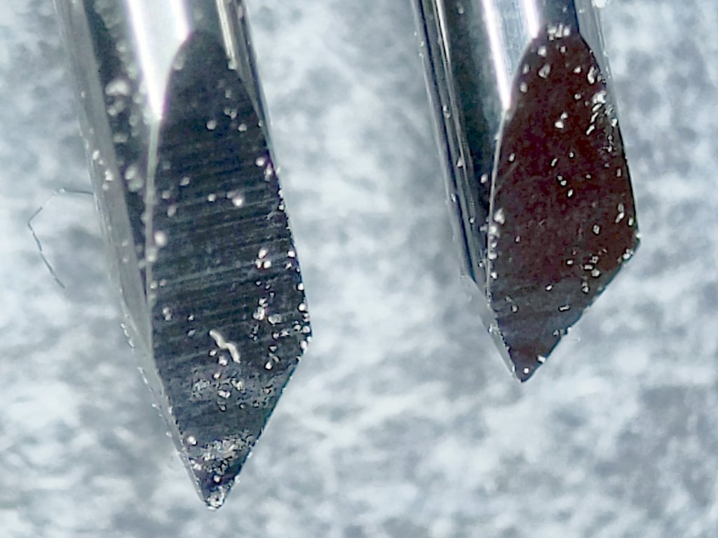
Having used the same two dragknifeblades intermittently over the last three-ish years, I wondered just how worn they’d gotten:
Drag Knife Blades – sides
For scale, the cylindrical part of the blade is 1.0 mm OD.
The blade with the longer face (left above and bottom below) has seen the most use and is definitely rounded at the tip:
Drag Knife Blades – tips
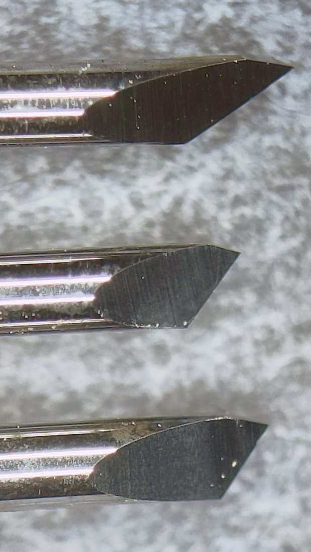
Three unused blades have sharp tips:
Drag Knife Blades – unused 60 45 30 degree
From the top, the (nominal) blade angles are 60°, 45°, and 30°, generally indicated by yellow, red, and blue plastic caps. However, various eBay sellers disagree on how to measure the angle (up from surface / outward from axis) and which cap colors correspond to which angles.
The unused 45° blade bracketed by the two used blades:
Drag Knife Blades – unused in center
The two lower blades have angles somewhere between 30° and 45°, suggesting slack grinder and QC tolerances. If the actual angle matters to you, buy an assortment (from one seller!), measure what you get, and don’t be surprised when the results aren’t anything in particular.
Perhaps, with careful attention to alignment in a non-pivoting / collet holder, one might scribe exceedingly narrow lines.
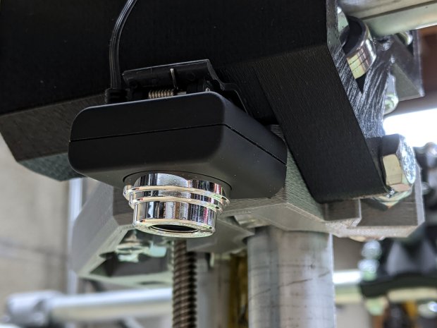
For the usual inscrutable reasons, updating bCNC killed the USB camera on the MPCNC, although it still worked fine with VLC. Rather than argue with it, I popped a more recent camera from the heap and stuck it onto the MPCNC central assembly:
bCNC – USB probe camera – attachment
This one has a nice rectangular case, although the surface might be horrible silicone that turns to snot after a few years. The fancy silver snout rotates to focus the lens from a few millimeters to infinity … and beyond!
If you think it looks a bit off-kilter, you’re absolutely right:
bCNC – USB probe camera – off-axis alignment
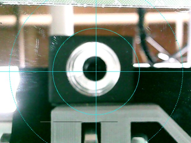
The lens image reflected in a mirror on the platform shows the optical axis has nothing whatsoever to do with the camera case or lens snout:
bCNC – USB probe camera – off-axis reflection
Remember, the mirror reflects the lens image back to itself only when the optical axis is perpendicular to the mirror. With the mirror flat on the platform, the lens must be directly above it.
Because the MPCNC camera rides at a constant height over the platform, the actual focus & scale depends on the material thickness, but this should be typical:
bCNC – USB Probe Camera – scale – screenshot
It set up a Tek Circuit Computer test deck within 0.2 mm and the other two within 0.1 mm, so it’s close enough.
The image looks a whole lot better: cheap USB cameras just keep improving …
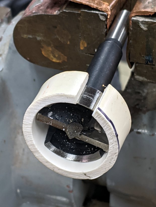
Another reducer had gone missing over the years, so I made one from a length of PVC pipe:
Bird Box – PVC pipe reducer – shaping
It started as 1-½ PVC pipe, 1-⅞ inch actual OD and should fit into a 1-½ hole, so I measured 1.5 × 3.15 around the circumference, bandsawed out the excess, draped it over a 1-½ Forstner bit, toasted it with a heat gun, and squashed it so it’s just a little bit bigger than the (enlarged!) hole in the box.
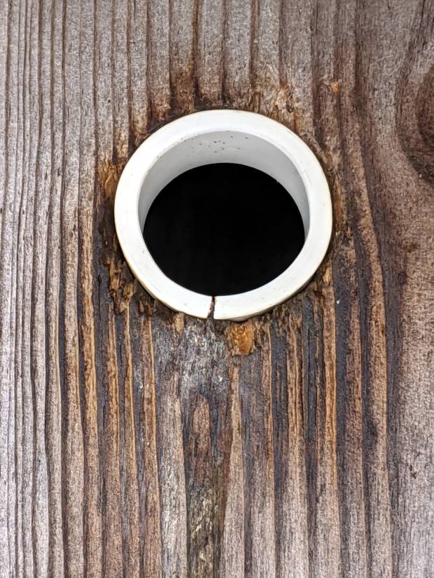
Now the entrance is 1-¼ (-ish), just like it should be:
Bird Box – PVC pipe reducer – installed
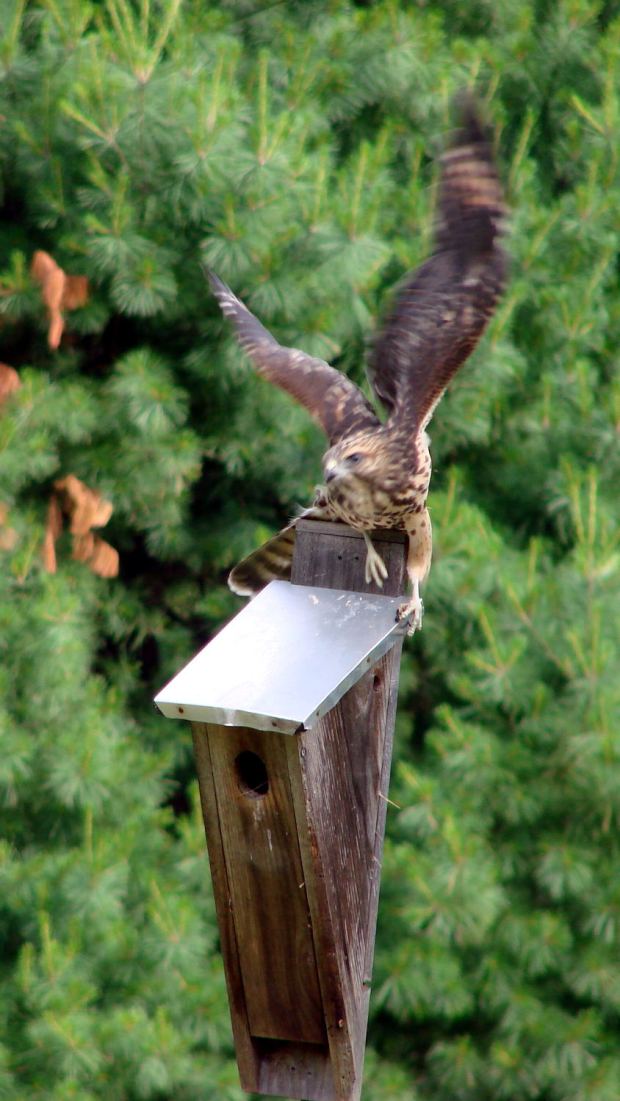
The bird box in the front yard has been attracting starlings, in addition to serving as a hawkperch:
New Coopers Hawks – bird box takeoff whoops
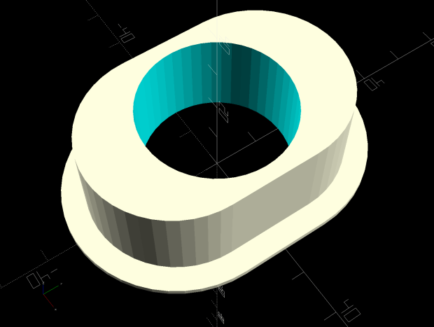
The oblong hole required advanced manufacturing techniques:
Oval Entrance Reducer
The front face should be too slick for larger birds and the little ones will zip right into the hole:
Bird Box – 3D printed entrance reducer
The two starlings who’d been evaluating the box seem to have moved on; we doubt they’re now homeless.
This file contains hidden or bidirectional Unicode text that may be interpreted or compiled differently than what appears below. To review, open the file in an editor that reveals hidden Unicode characters.
Learn more about bidirectional Unicode characters
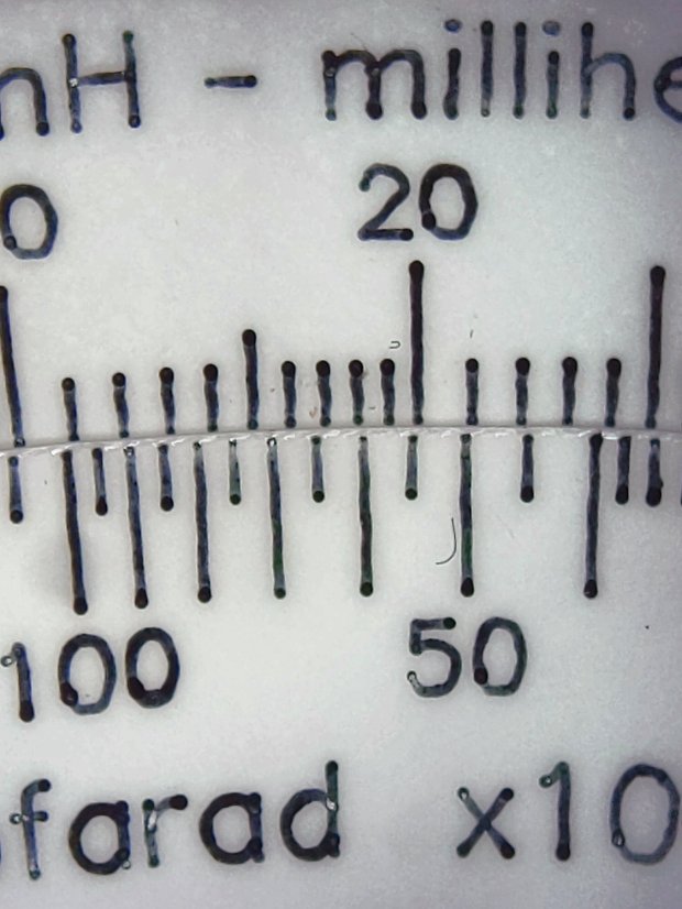
The digits look like they’re embossed into the surface with shaped punches, rather than engraved like the lines. Of course, I don’t know how K&E’s production machinery worked.
A closer view:
KE Deci-Lon Slide Rule – scale detail – digits
I think 0.1 mm is an aggressively narrow trace width, even for a laser engraver.
The quadrature detector, the black block on the left, is oriented with its lens (and, thus, the actual detectors) pointed away from the IR emitter. I thought it might be an assembly screwup, but it’s actually worse: the PCB layout is wrong.
A note from Tristan in NZ explains the situation:
So I have a later model than yours. It has a 2nd PCB chunk between where the legs normally would be. Just a floating piece with two holes for the legs, holding the legs from the board […] to the main board.It is also pointing the correct way (with the lens towards the three leg emitter).
Kensington scroll wheel revision2
The new quad detector has only three pins and no convex lens, but the active area now faces the emitter across the gap.
Because the interposer PCB occupies the space previously devoted to the emitter & detector leads, Kensington apparently soldered the new parts directly to the top surface without any clearance:
It’s like they failed to put through-vias to the rear or didn’t route them to the bottom another way, hence the solder is under the component
Tristan managed to wreck the detector while attempting to re-solder the intermittent joints, a situation I’m painfully familiar with. He replaced it with a quad detector harvested from a mid-90s optical mouse and it’s back in operation.
So I think the correct “fix” for the old-style PCBs (without the new interposer) is to unsolder the detector, rotate it so the lens faces the emitter, then somehow rewire the pins to the original pads. This won’t be easy and definitely won’t be pretty, but as long as it’s pointed in the right general direction it should work:
mine works off axis quite a bit
Should either of my Expert Mouse trackballs fail, now I know what to do
Many thanks to Tristan for reporting his findings!