The LED strip lights have a reasonably diffuse pattern with an on-axis bright area that puts more light on the rear of the counter than seems strictly necessary. Revising the original brackets to tilt the strips moves the bright patch half a foot forward:

For lack of anything smarter, the angle puts the diagonal of the LED strip on the level:

The translucent block represents the strip (double-thick and double-wide), with a peg punching a hole for the threaded brass insert.
Although the source code has an option to splice the middle blocks together, it can also build them separately:
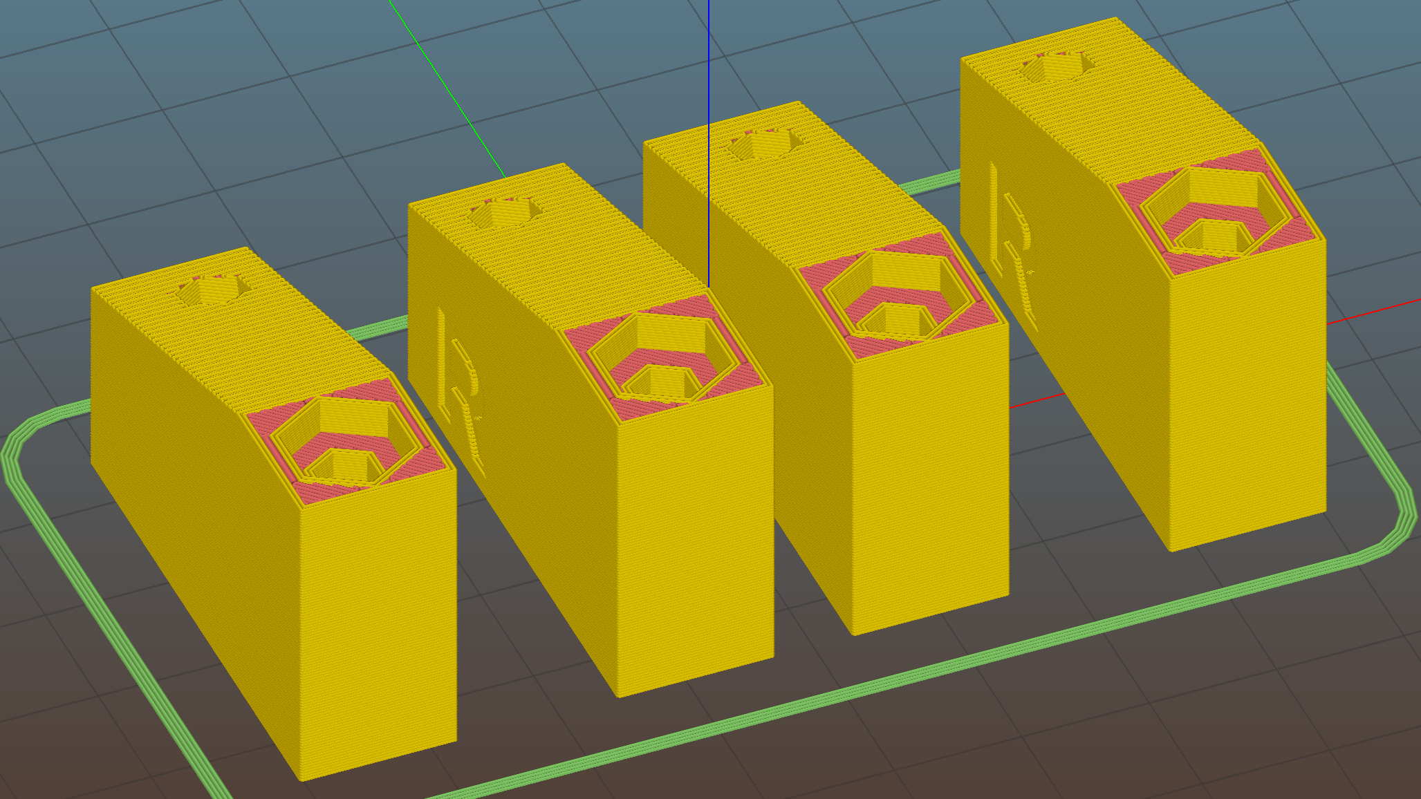
Turns out they’re easier to assemble that way; screw ’em to the strips, then screw the strips to the cabinet.
I moved the deck screw holes to the other end of the block, thus putting the strips against the inside of the cabinet face. It turns out the IR sensor responds to the DC level of the reflected light, not short-term changes, which meant the reflection from the adjacent wood blinded it to anything waved below. Adding a strip of black electrical tape killed enough of the reflected light to solve that problem:
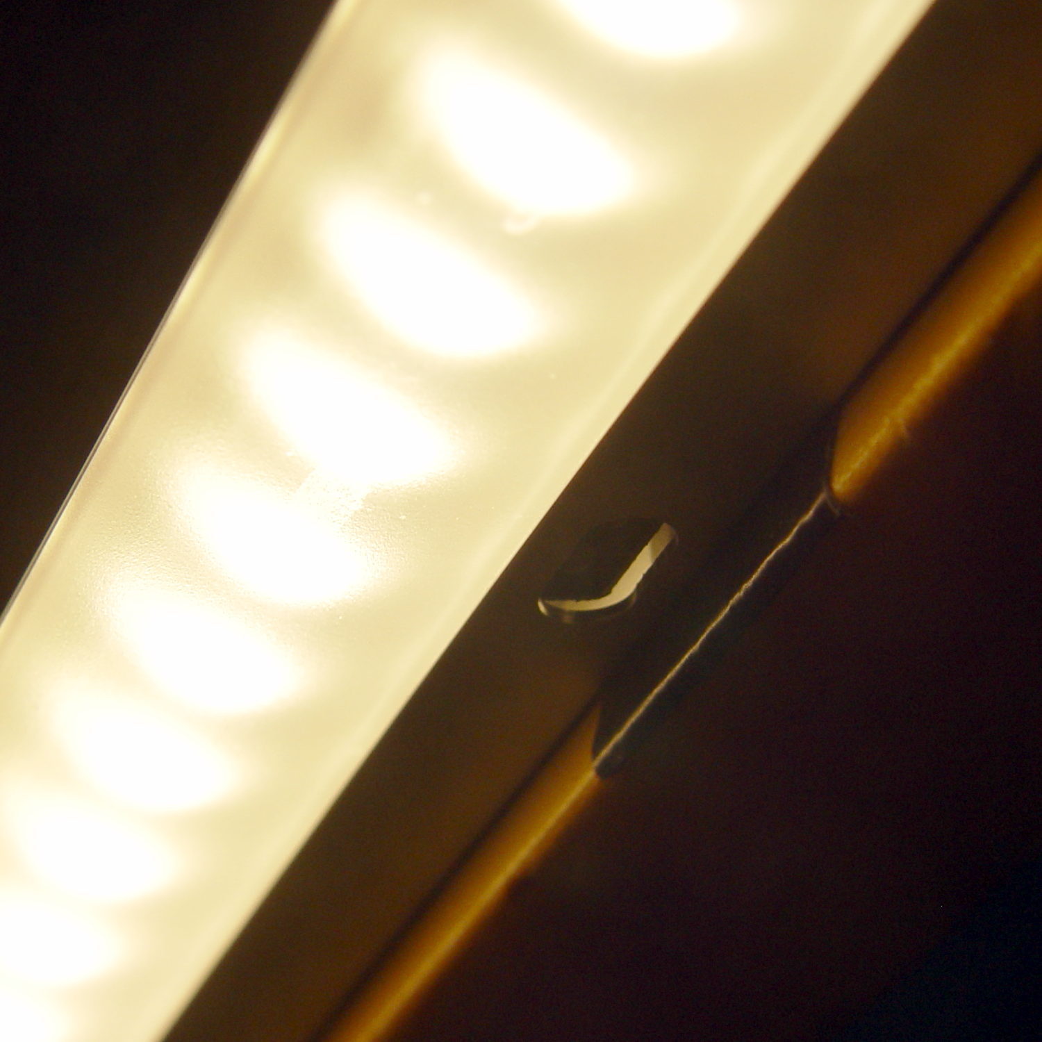
The tape isn’t quite as far off-center as it looks, but I’m glad nobody will ever see it …
The before-and-after light patterns, as viewed on B-size metric graph paper centered on the left-hand strip and aligned with the belly side of the countertop:

Those look pretty much the same, don’t they? So much for photography as evidence for anything.
The OpenSCAD source code as a GitHub Gist:
This file contains hidden or bidirectional Unicode text that may be interpreted or compiled differently than what appears below. To review, open the file in an editor that reveals hidden Unicode characters.
Learn more about bidirectional Unicode characters
| // Mounting brackets for eShine under-counter LED lights | |
| // Ed Nisley KE4ZNU December 2016 | |
| Layout = "Build"; | |
| //- Extrusion parameters must match reality! | |
| ThreadThick = 0.25; | |
| ThreadWidth = 0.40; | |
| HoleWindage = 0.2; | |
| Protrusion = 0.1; // make holes end cleanly | |
| inch = 25.4; | |
| function IntegerMultiple(Size,Unit) = Unit * ceil(Size / Unit); | |
| //———- | |
| // Dimensions | |
| MountHeight = (1 + 0*3/16) * inch; // distance from cabinet bottom | |
| THREADOD = 0; | |
| HEADOD = 1; | |
| LENGTH = 2; | |
| WoodScrew = [4.0,8.3,41]; // 8×1-5/8 Deck screw | |
| WoodScrewRecess = 3.0; | |
| WoodScrewMargin = 1.5 * WoodScrew[HEADOD]; // head OD + flat ring | |
| Insert = [3.9,4.6,5.8 + 2.0]; // 4-40 knurled brass insert | |
| JoinerLength = 19.0; // joiner between strips | |
| LEDEndBlock = [11.0,28.8,9.5]; // LED plastic end block | |
| LEDScrewOffset = [1.0,8.2,0]; // hole offset from end block center point | |
| StripAngle = atan2(LEDEndBlock[2],LEDEndBlock[1]); | |
| echo(str("Strip angle: ",StripAngle)); | |
| MountBlock = [WoodScrewMargin,(WoodScrewMargin + LEDEndBlock[1]*cos(StripAngle)),MountHeight]; | |
| //———————- | |
| // Useful routines | |
| module PolyCyl(Dia,Height,ForceSides=0) { // based on nophead's polyholes | |
| Sides = (ForceSides != 0) ? ForceSides : (ceil(Dia) + 2); | |
| FixDia = Dia / cos(180/Sides); | |
| cylinder(d=(FixDia + HoleWindage),h=Height,$fn=Sides); | |
| } | |
| //—– | |
| // LED end block with positive insert for subtraction | |
| // returned with mounting hole end of strip along X axis | |
| // ready for positioning & subtraction | |
| module EndBlock(Side = "L") { | |
| LSO = [((Side == "L") ? 1 : -1)*LEDScrewOffset[0],LEDScrewOffset[1],LEDScrewOffset[2]]; | |
| rotate([-StripAngle,0,0]) | |
| translate([0,LEDEndBlock[1]/2,LEDEndBlock[2]]) | |
| union() { | |
| cube(LEDEndBlock + [LEDEndBlock[0],0,LEDEndBlock[2]],center=true); | |
| translate(LSO + [0,0,-(LEDEndBlock[2] + Insert[2])]) | |
| rotate(180/6) | |
| PolyCyl(Insert[1],2*Insert[2],6); | |
| } | |
| } | |
| //—– | |
| // End mounting block with proper hole offsets | |
| module EndMount(Side = "L") { | |
| translate([0,0,MountBlock[2]/2]) | |
| difference() { | |
| translate([0,MountBlock[1]/2,0]) | |
| cube(MountBlock,center=true); | |
| translate([0,WoodScrewMargin,MountBlock[2]/2]) | |
| EndBlock(Side); | |
| translate([0,WoodScrewMargin/2,-MountBlock[2]]) | |
| rotate(180/6) | |
| PolyCyl(WoodScrew[THREADOD],2*MountBlock[2],6); | |
| translate([0,WoodScrewMargin/2,(MountBlock[2]/2 – WoodScrewRecess)]) | |
| rotate(180/6) | |
| PolyCyl(WoodScrew[HEADOD],WoodScrewRecess + Protrusion,6); | |
| translate([((Side == "L") ? 1 : -1)*MountBlock[0]/2,3*MountBlock[1]/4,-MountBlock[2]/4]) | |
| rotate([90,0,((Side == "L") ? 1 : -1)*90]) | |
| translate([0,0,-2*ThreadThick]) | |
| linear_extrude(height=4*ThreadThick,convexity=3) | |
| text(Side,font=":style=bold",valign="center",halign="center"); | |
| } | |
| } | |
| module MidMount() { | |
| XOffset = (JoinerLength + MountBlock[0])/2; | |
| BridgeThick = 5.0; | |
| union() { | |
| translate([XOffset,0,0]) | |
| EndMount("L"); | |
| translate([0,MountBlock[1]/2,BridgeThick/2]) | |
| cube([JoinerLength,MountBlock[1],BridgeThick] + [2*Protrusion,0,0],center=true); | |
| translate([-XOffset,0,0]) | |
| EndMount("R"); | |
| } | |
| } | |
| //———- | |
| // Build them | |
| if (Layout == "EndBlock") | |
| EndBlock("L"); | |
| if (Layout == "EndMount") | |
| EndMount("R"); | |
| if (Layout == "MidMount") | |
| MidMount(); | |
| if (Layout == "BuildJoined") { | |
| translate([-(JoinerLength + 2*MountBlock[0]),0,0]) | |
| EndMount("L"); | |
| MidMount(); | |
| translate([(JoinerLength + 2*MountBlock[0]),0,0]) | |
| EndMount("R"); | |
| } | |
| if (Layout == "Build") { | |
| translate([-MountBlock[0],0,0]) | |
| EndMount("L"); | |
| translate([MountBlock[0],0,0]) | |
| EndMount("R"); | |
| } |

Comments
3 responses to “Under-cabinet Lamp Brackets: Angled Edition”
As you pointed out in your “Spectrometer: Quick and Dirty Image Processing” post, you don’t have to use photography directly to measure intensity distribution, you extract a strip from the image and graph it.
Glad somebody’s paying attention around here; I forgot about that trick. [sigh]
Angling the strip dimmed the light washing the wall beyond the counter and brightened the light spilling over onto the floor, to the extent there’s now a foot-wide bright strip along the middle of the floor where the light from both sides overlaps.
[…] a little tab to the angled brackets prevents them from pivoting while you’re tightening the mounting screw into the brass […]