Ed Nisley's Blog: Shop notes, electronics, firmware, machinery, 3D printing, laser cuttery, and curiosities. Contents: 100% human thinking, 0% AI slop.
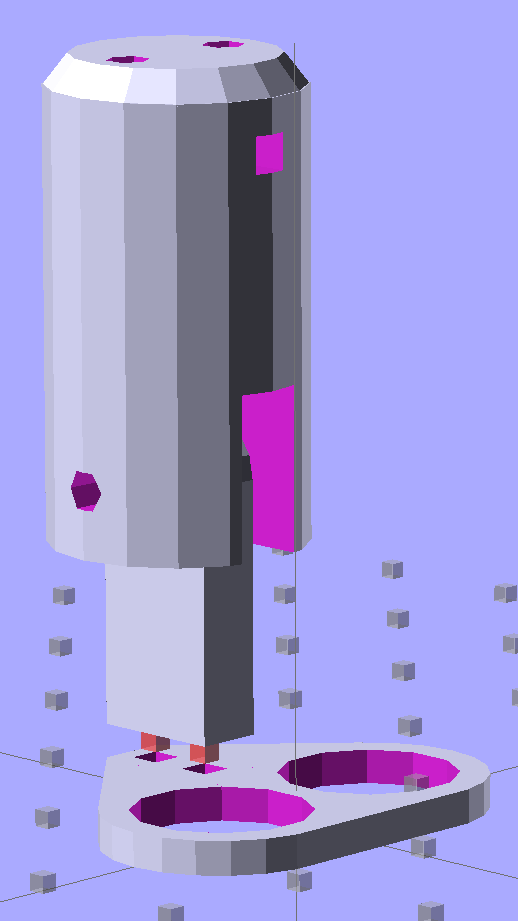
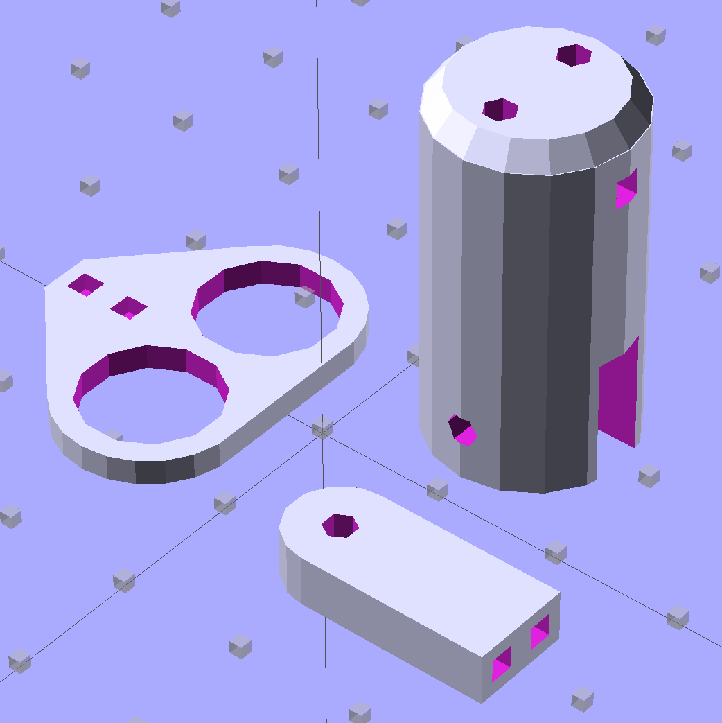
Some trial fitting with the prototype showed that there’s no possible way to route the connections through the socket, no matter how much I wanted that to happen, so I rotated the body to align the LEDs with the socket pin slots:
Sears Lamp LED Adapter – Show view
The body now builds with the flat end down, so the overall finish should be better:
Sears Lamp LED Adapter – Build view
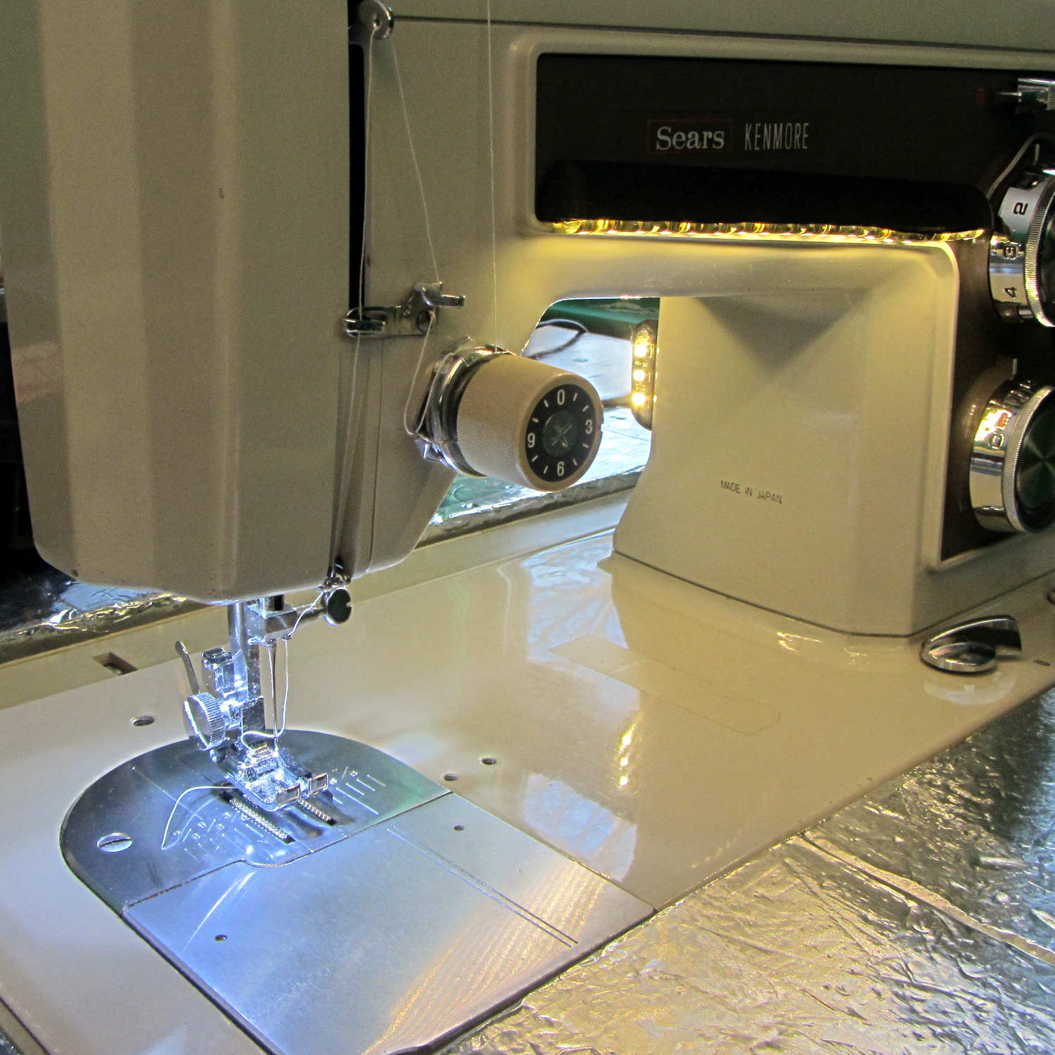
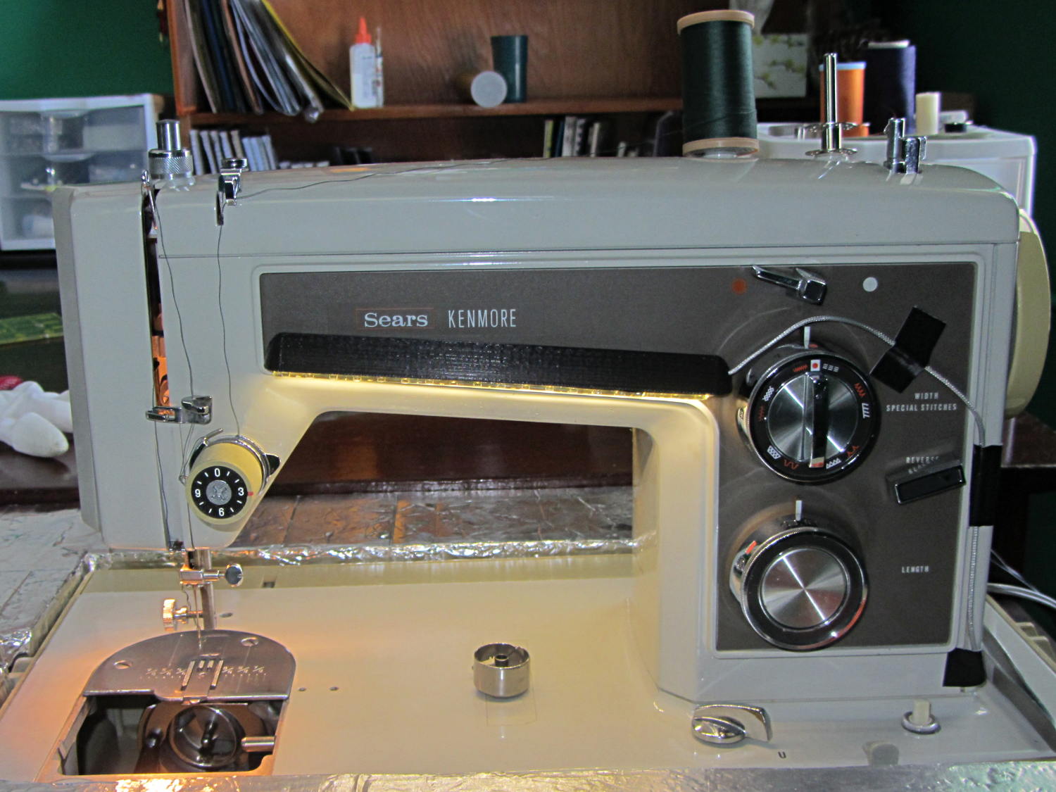
A test run shows why I really, really wanted cool white LEDs in the strips over the arm:
Kenmore 158 Sewing Machine – mixed LED lighting
The LED mount doesn’t have quite enough room inside the end cap for the holder to tilt as I wanted; the two 10 mm LEDs can be about 10 mm lower and slightly closer to the shaft driving the needle, which is what this rapid prototyping stuff is all about. Scrapping the existing lamp socket and (120 VAC!) wiring seems the best way to make this more useful.
Early reports on the arm LEDs indicate a requirement for more light, so the next iteration of those mounts will put two strips side-by-side…
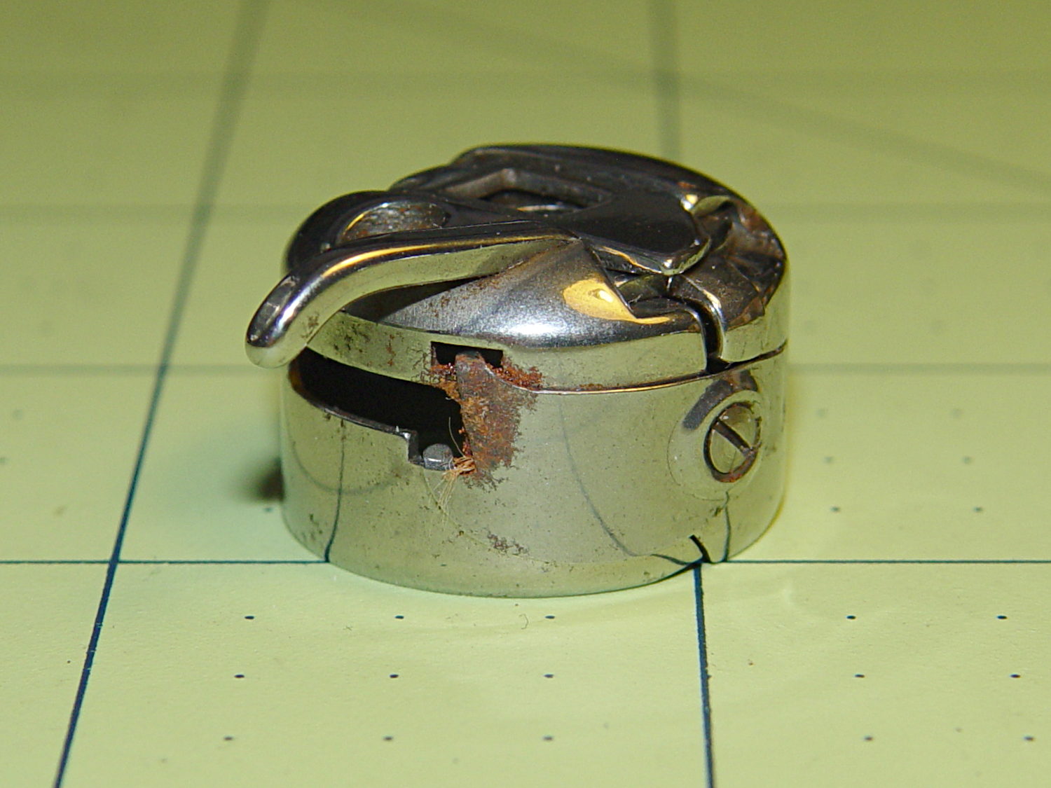
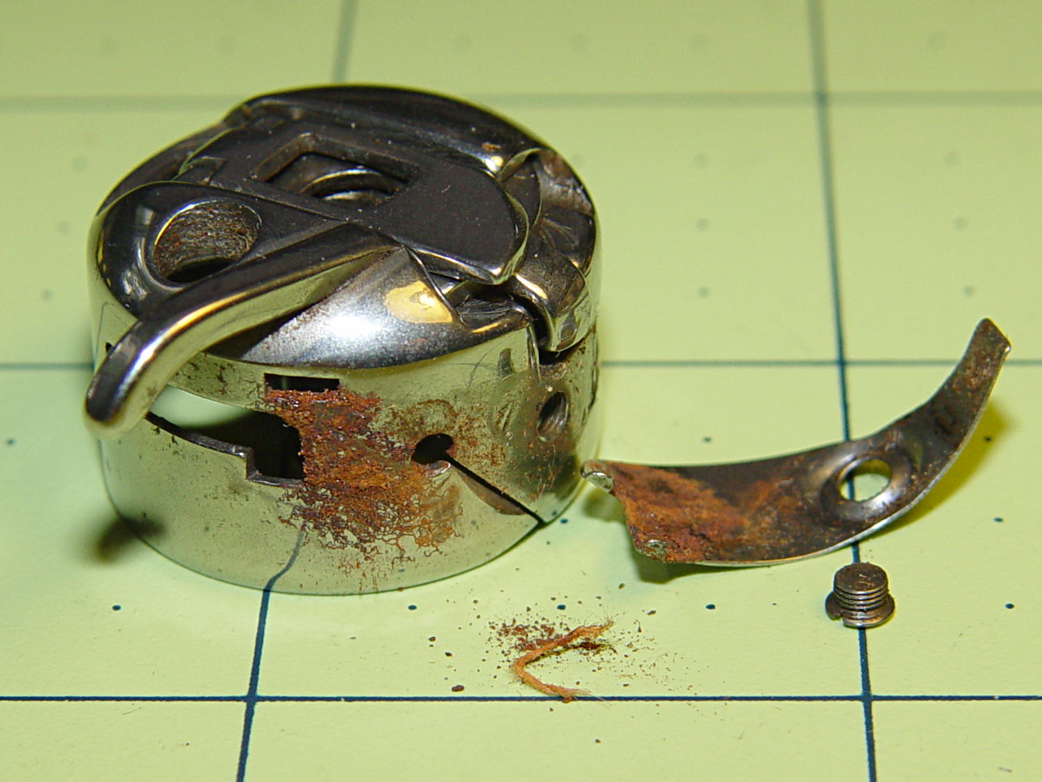
I picked up a spare sewing machine as a crash test dummy for modifications to Mary’s Kenmore Model 158. It’s in reasonably good condition, although the bobbin case showed a bit of rust:
Kenmore bobbin case – rusted overview
Taking the tension spring off revealed more rust:
Kenmore bobbin case – rusted parts
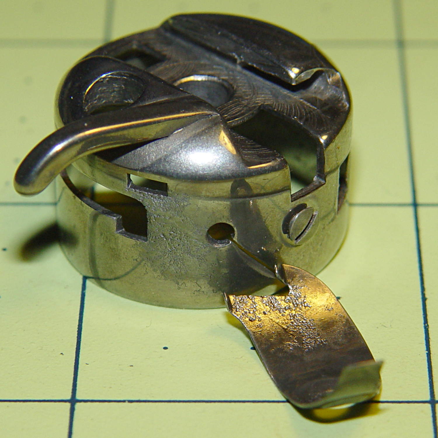
An overnight soak in Evapo-Rust got rid of the corrosion and left the pits behind:
Kenmore bobbin case – restored parts
Those imperfections on the tension spring are pits, not bumps, despite their appearance.
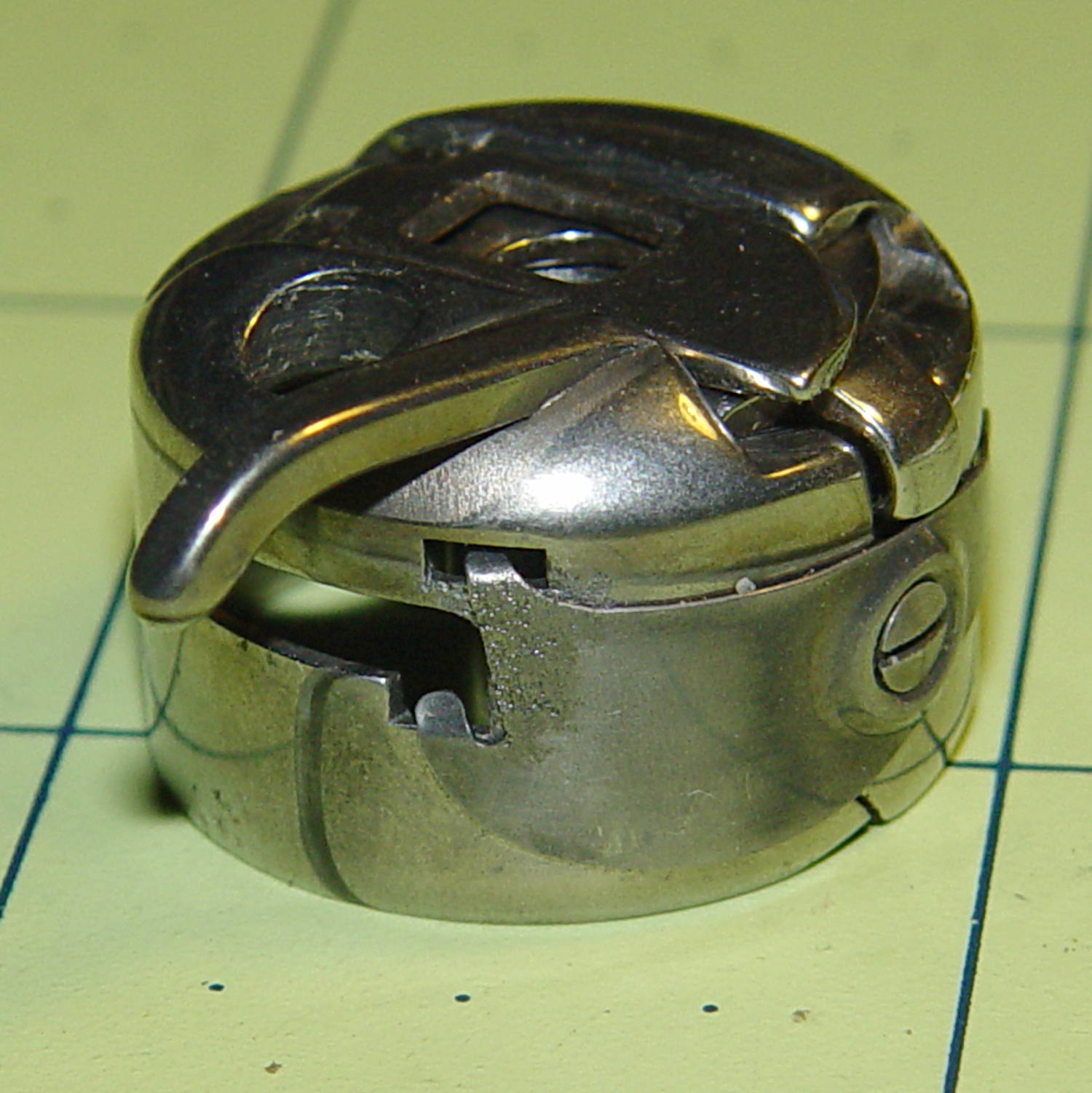
It doesn’t seem so bad from the outside:
Kenmore bobbin case – restored
It probably won’t work nearly as well as it should, this being one place where a smooth surface counts for a lot. Fortunately, it’s just a crash test dummy machine and good results aren’t critical.
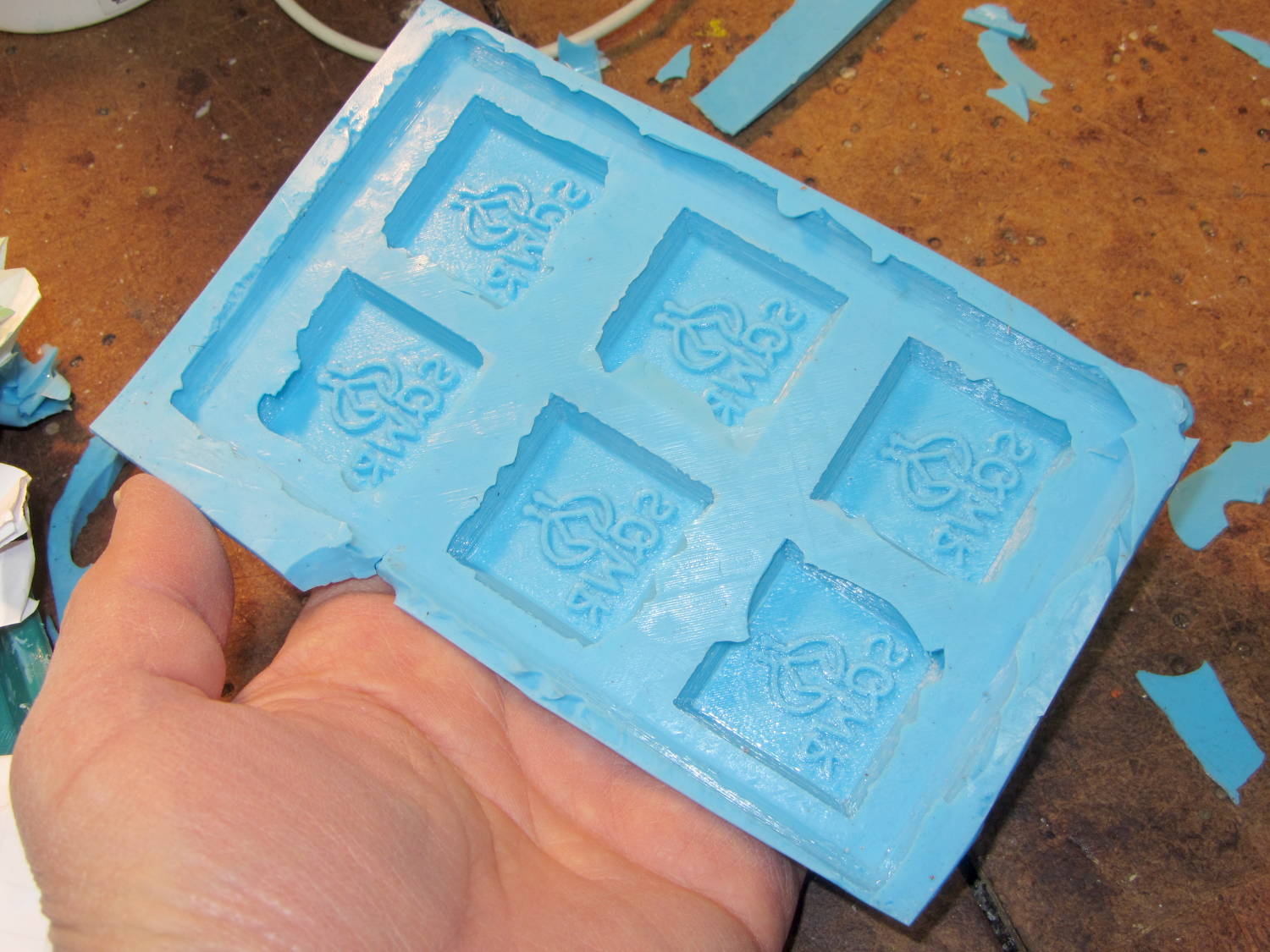
A closeup shows that the characteristic 3D printed striations came through perfectly on the silicone:
SqWr chocolate molds – silicone interior detail
In this application, the 3D printer’s hand-knitted look is desirable, but most molds would benefit from manual smoothing / sanding / filling; perhaps slathering release agent over the molds would help. In any event, the silicone didn’t lock to the striations and parted easily, so it’s all good.
The first layer of silicone worked its way between the positive molds and the slab; Tesa says the positives were so well attached to the pegs that she forgot to apply double-sided tape between them. No harm done: the flashing peeled / trimmed off easily enough.
She thinks a shallow block mold would work just as well for a slab like this: you’d (well, she’d) save hours of tedious layering. The block mold wouldn’t use any more silicone, as the mixing cup had plenty of residue after each layer, even after scraping: doing just one mixing, one pouring, and one curing stage would be a major win.
Something Went Wrong during the elaborate dance my M2 goes through to home all three axes, resulting in the platform heater connector whacking the nozzle from the rear, the nozzle dragging off the platform to the right, and then jamming on the edge of the too-high platform on the way back. As nearly as I can tell, the command to lower the platform before doing anything else didn’t happen, after which things slid rapidly downhill.
There are disadvantages to having powerful motors and rigid machinery, but in this case the advantages outweigh them. You should browse Youtube’s collection of CNC mishaps to see what a real machine tool crash looks like.
I think that’s the second time the thing has misbehaved, so it’s doing OK. I have seen a few instances where the firmware doesn’t obey the acceleration limits, but I don’t have any way to verify what happened. If the Z-axis motor stalled while lowering the platform, that would explain everything; that same G-Code has worked flawlessly for nearly a year.
After realigning the extruder motor and checking that the hot end hadn’t gotten dislodged, I ran off a thinwall open box that showed the extruder was about 0.1 mm lower than before. That called for a tweak to the G92 setting in the startup G-Code that defines the offset between the two.
After that, I figured it would be a Good Idea to check the platform leveling, so I arranged five boxes on the platform:
M2 Platform Leveling – thinwall open box layout
About 8 minutes later, I had the five values at the top of this scratch paper:
M2 Platform Leveling Data
Tweaking the three leveling screws under the platform and iterating with more boxes eventually got the platform aligned to about ±0.07 mm across the 200×250 mm platform diagonal; supper got in the way of repeating the last test. The bird’s nest failure of the left-front box in that test looked like an adhesion problem; in the heat of it all, I built four sets of thinwall boxes on exactly the same spots without renewing the hairspray coating.
Measuring the skirt and box heights suggested a bit of adjustment to the initial Z offset. A static measurement comes pretty close, but the actual results are what matters.
I’ll recheck the alignment at some point, but for now it’s back in operation…
The current startup G-Code from Slic3r’s configuration:
;-- Slic3r Start G-Code for M2 starts --
;  Ed Nisley KE4NZU - 15 Nov 2013
;  28 Feb 2014 tweak Z offset
; Z-min switch at platform, must move nozzle to X=130 to clear
M140 S[first_layer_bed_temperature]	; start bed heating
G90				; absolute coordinates
G21				; millimeters
M83				; relative extrusion distance
G92 Z0			; set Z to zero, wherever it might be now
G1 Z10 F1000	; move platform downward to clear nozzle; may crash at bottom
G28 Y0			; home Y to be sure of clearing probe point
G92 Y-127 		; set origin so 0 = center of plate
G28 X0			; home X
G92 X-95		; set origin so 0 = center of plate
G1 X130 Y0 F30000	; move off platform to right side, center Y
G28 Z0			; home Z with switch near center of platform
G92 Z-4.40		; set origin to measured z offset
G0 Z2.0			; get air under switch
G0 Y-127 F10000	; set up for priming, zig around corner
G0 X0			;  center X
M109 S[first_layer_temperature]	; set extruder temperature and wait
M190 S[first_layer_bed_temperature]	; wait for bed to finish heating
G1 Z0.0 F500	; plug extruder on plate
G1 E25 F300		; prime to get pressure, generate blob
G1 Z5 F2000		; rise above blob
G1 X15 Y-125 F30000	; jerk away from blob, move over surface
G1 Z0.0 F1000	; dab nozzle to attach outer snot to platform
G4 P1			; pause to attach
G1 X35 F500		; slowly smear snot to clear nozzle
G1 Z1.0 F2000	; clear bed for travel
;-- Slic3r Start G-Code ends --
Clamping a long-stroke dial indicator to the M2’s X axis gantry:
Dial indicator – gantry to M2 Y rail
Then stuffing manual G-Code into Pronterface produced some data on Z-axis accuracy, repeatability, and hysteresis:
M2 Z-axis positioning measurements
Note that the commanded positions are in 0.001 mm units (25 = 0.025 mm) and the observed positions are in mils (1 = 0.001 inch). The arrows indicate which way the stage moved, with positive Z increments moving the stage down.
The overall distance seems to be quantized at 0.0150 mm = 6 step intervals. You can command a motion between those steps (G0 Z0.0025, G0 Z0.0075, etc), but the motor doesn’t turn until the distance exceeds the next interval (G0 Z0.0150 causes motion). This isn’t stiction, because the firmware isn’t activating the motor.
Stepping up and down in 0.025 mm increments (10 steps, but not an even multiple of the 6 step quantization intervals) over a 0.100 mm range produces about 0.01 mm = 4 steps of backlash. Some of that definitely comes from the quantization interval, but it’s not consistent, so there’s also mechanical backlash.
Frankly, that’s better than I expected, but any motion less than about 4 steps probably won’t happen and the errors are on the same order. Whether the firmware itself can compute and apply a smaller motion isn’t clear.
The controller doesn’t know where the platform is, at least in an open-loop stepper system. That means when the commanded motion is on the same order as the backlash, the controller can’t make the proper adjustments. As long as the positioning error remains smaller than the tolerance, it’s all good; expecting 0.020 mm resolution and accuracy seems reasonable.
But it’s only a quick-and-dirty test, so I wouldn’t read too much into it.
Solder pretty cable with silver plating on the braid (it’s probably mil-spec Teflon dielectric RG-174 coaxial cable) to the LEDs
Conjure a coax power connector and wall wart
Apply foam squares to mounts
Affix to sewing machine
The front LEDs have a jaunty angle along the bottom of the plastic panel:
Kenmore Model 158 Sewing Machine – LED Lights – front
You can see why I want cool-white LEDs, rather than these warm-white ones, to match the daylight from the window to the right. The wash of orange light from the incandescent bulb inside the end bell has got to go, too.
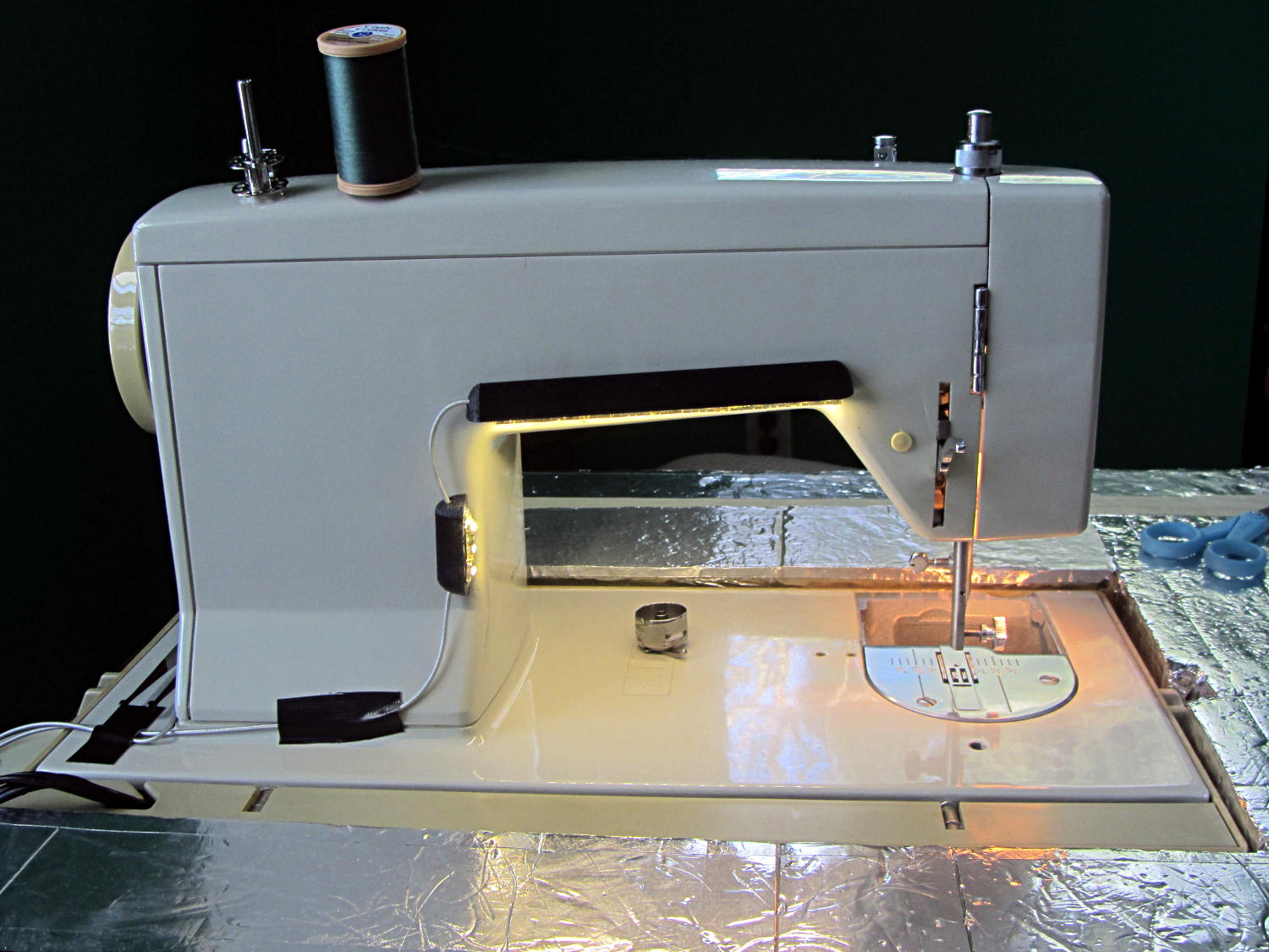
The rear LEDs over the arm may be slightly too close to the opening:
Kenmore Model 158 Sewing Machine – LED Lights – rear
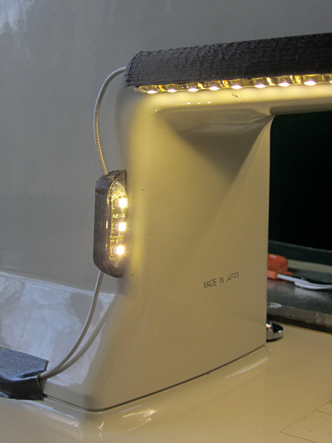
The single-segment strip on the side provides a bit more light for the needle across the opening:
Kenmore Model 158 Sewing Machine – LED Lights – rear detail
Now, I’ll grant you that the strips of of black Gorilla Tape aren’t particularly attractive, but the intent here is to find out whether the LEDs produce enough light, don’t snag the quilt, and generally meet requirements.
My old Thing-O-Matic has new life as the Frank-O-Squid at Squidwrench Galactic HQ, with all the original Makerbot electronics replaced by an Azteeg X3 controller. Over the last several weeks I’ve coaxed it into doing most of the right things at the proper speeds & feeds, so we can now move on to actually making stuff:
Frank-o-Squid in action
The warping on that little digital caliper thumbwheel holder show that I don’t have the tiny-object slowdown settings quite correct, but it’s getting close.
The Marlin firmware is on GitHub. I intended to set it up so that pulling changes from upstream Marlin would be easy, but totally blundered something along the way. I’ll eventually plug the changes from Configuration.h, Configuration_adv.h, and pins.h into a clean branch and start over, but, for now, we’re slowly diverging from consensus reality.
Although the platform still has the Z-min switch over on the right edge, neither the firmware nor Slic3r pay any attention to it. A stub in the startup G-Code sequence does a head fake toward the switch, but doesn’t actually probe it.
I scrapped the original craptastic Makerbot ATX power supply and replaced it with Makergear’s huge 12 V laptop brick that powered the original M2 platform, so the thermal switches on the extruder no longer do anything useful; it’s running bare, pretty much like all other 3D printers.
The Slic3r configuration exports thusly:
# generated by Slic3r 1.0.0RC1 on Mon Mar  3 07:48:29 2014
avoid_crossing_perimeters = 0
bed_size = 105,120
bed_temperature = 100
bottom_solid_layers = 3
bridge_acceleration = 0
bridge_fan_speed = 100
bridge_flow_ratio = 1
bridge_speed = 40
brim_width = 1.0
complete_objects = 0
cooling = 1
default_acceleration = 0
disable_fan_first_layers = 1000
duplicate = 1
duplicate_distance = 6
duplicate_grid = 1,1
end_gcode = ;---- end.gcode starts ----\n; TOM 286 - Al plates + Geared extruder\n; Ed Nisley - KE4ZNU - January 2014\n; Marlin with tweaks for Azteeg X3 with thermocouple\n;- inhale filament blob\nG91\nG1 E-5 F900\nG90\n;- turn off heaters\nM104 S0         ; extruder head\nM140 S0         ; HBP\n;- move to eject position\nG0 Z115 F1000   ; home Z to get nozzle away from object\n;G92 Z115      ; reset Z\nG1 X0 F6000     ; center X axis\nG1 Y35          ; move Y stage forward\n;---- end.gcode ends ----
external_perimeter_speed = 50%
external_perimeters_first = 0
extra_perimeters = 1
extruder_clearance_height = 20
extruder_clearance_radius = 20
extruder_offset = 0x0
extrusion_axis = E
extrusion_multiplier = 0.95
extrusion_width = 0.50
fan_always_on = 0
fan_below_layer_time = 1
filament_diameter = 2.95
fill_angle = 45
fill_density = 0.15
fill_pattern = honeycomb
first_layer_acceleration = 0
first_layer_bed_temperature = 100
first_layer_extrusion_width = 0.50
first_layer_height = 0.25
first_layer_speed = 10
first_layer_temperature = 210
g0 = 0
gap_fill_speed = 30
gcode_arcs = 0
gcode_comments = 0
gcode_flavor = reprap
infill_acceleration = 0
infill_every_layers = 2
infill_extruder = 1
infill_extrusion_width = 0.50
infill_first = 1
infill_only_where_needed = 1
infill_speed = 50
layer_gcode =
layer_height = 0.25
max_fan_speed = 100
min_fan_speed = 35
min_print_speed = 10
min_skirt_length = 3
notes =
nozzle_diameter = 0.4
only_retract_when_crossing_perimeters = 1
ooze_prevention = 0
output_filename_format = [input_filename_base].gcode
overhangs = 1
perimeter_acceleration = 0
perimeter_extruder = 1
perimeter_extrusion_width = 0.50
perimeter_speed = 30
perimeters = 1
post_process =
print_center = 0,0
raft_layers = 0
randomize_start = 1
resolution = 0.05
retract_before_travel = 0.0
retract_layer_change = 0
retract_length = 0.75
retract_length_toolchange = 10
retract_lift = 0
retract_restart_extra = 0
retract_restart_extra_toolchange = 0
retract_speed = 30
rotate = 0
scale = 1
skirt_distance = 2
skirt_height = 1
skirts = 1
slowdown_below_layer_time = 30
small_perimeter_speed = 50%
solid_fill_pattern = rectilinear
solid_infill_below_area = 5
solid_infill_every_layers = 0
solid_infill_extrusion_width = 0.50
solid_infill_speed = 150%
spiral_vase = 0
standby_temperature_delta = -5
start_gcode = ;---- start.gcode begins ----\n; TOM 286 - Al plates + Geared extruder + Zmin platform sense\n; Ed Nisley - KE4ZNU - January 2014\n; Marlin with tweaks for Azteeg X3 with thermocouple\n;\n; Set initial conditions\nG21                 ; set units to mm\nG90                 ; set positioning to absolute\n;----------\n; Begin heating\nM104 S[first_layer_temperature]         ; extruder head\nM140 S[first_layer_bed_temperature]	; start bed heating\n;----------\n; Home axes\nG28 X0 Y0 Z0\nG92 X-53.5 Y-58.5 Z114.5\n;----------\n; Initial nozzle wipe to clear snot for Z touchoff\nG1 X0 Y0 Z3.0 F1000     ; pause at center to build confidence\nG4 P1000\nG1 Z10                  ; ensure clearance\nG1 X39 Y-58.0 F1000    ; move to front, avoid wiper blade\nG1 X55                  ; to wipe station\nG1 Z6.0                 ; to wipe level\nM116                    ; wait for temperature settling\nG1 Y-45 F500            ; slowly wipe nozzle\n;-----------------------------------------------\n; Z platform height touchoff\n; Make sure the XY position is actually over the switch!\n; Home Z downward to platform switch\n; Compensate for 0.05 mm backlash in G92: make it 0.05 too low\nG1 X56.0 Y8.2 F5000\nG1 Z4.0 F1000     ; get over build platform switch\n;G1 Z0 F50                    ; home downward very slowly\n;G92 Z1.45                    ; set Z-min switch height\nG1 Z6.0 F1000                ; back off switch to wipe level\n;-----------------------------------------------\n; Prime extruder to stabilize initial pressure\nG1 X55 Y-45 F5000   ; set up for wipe from rear\nG1 Y-58.0 F500      ; wipe to front\nG91                 ; use incremental motion for extrusion\nG1 F100               ; set decent rate\nG1 E10              ; extrude enough to get good pressure\nG1 F2000            ; set for fast retract\nG1 E-1.0            ; retract\nG90                 ; back to absolute motion\nG1 Y-45 F1000       ; wipe nozzle to rear\n;----------\n; Set up for Skirt start in right front corner\n; Compensate for Z backlash: move upward from zero point\nG1 X40 Y-40 F5000\nG1 Z0.0 F1000     ; kiss platform\nG1 Z0.2 F1000       ; take up Z backlash to less than thread height\n;G92 E1.0            ; preset to avoid huge un-Reversal blob\n;G1 X0 Y0\n;---- start.gcode ends ----
start_perimeters_at_concave_points = 1
start_perimeters_at_non_overhang = 1
support_material = 0
support_material_angle = 0
support_material_enforce_layers = 0
support_material_extruder = 1
support_material_extrusion_width = 0.50
support_material_interface_extruder = 1
support_material_interface_layers = 3
support_material_interface_spacing = 0
support_material_pattern = honeycomb
support_material_spacing = 2.5
support_material_speed = 60
support_material_threshold = 0
temperature = 210
thin_walls = 1
threads = 2
toolchange_gcode =
top_infill_extrusion_width = 0.50
top_solid_infill_speed = 50%
top_solid_layers = 3
travel_speed = 150
use_firmware_retraction = 0
use_relative_e_distances = 0
vibration_limit = 0
wipe = 0
z_offset = 0
All of that should become three TOM286 - Default sub-profiles.
The Pronterface configuration looks like this:
set port /dev/ttyUSB0
set monitor True
set last_bed_temperature 100.0
set last_temperature 210.0
set baudrate 115200
set temperature_abs 210
set xy_feedrate 5000
set z_feedrate 1000
set build_dimensions 110.00x120.00x117.00+0.00+0.00+0.00+0.00+0.00+0.00
set extruders 1
set slic3rintegration True
set tempgauges True
set preview_extrusion_width 0.4
set e_feedrate 100
set last_extrusion 3
set last_file_path /home/ed/Documents/Thing-O-Matic/Calibration/Thread Thickness
set recentfiles ["/home/ed/Documents/Thing-O-Matic/Calibration/Thread Thickness/Caliper Thumbwheel Holder.gcode", "/home/ed/Documents/Thing-O-Matic/Calibration/Thread Thickness/Thinwall Open Box.gcode", "/home/ed/Documents/Thing-O-Matic/Calibration/Thread Thickness/Platform Level.gcode", "/home/ed/Documents/Thing-O-Matic/Calibration/Circle Diameter Calibration/Small Circle Cal - M2 0.2 mm.gcode", "/home/ed/Documents/Thing-O-Matic/Calibration/Circle Diameter Calibration/Small Circle Cal - TOM.gcode"]
As you can see, it’s all running from a directory on my old laptop. The next step involves migrating everything to a dedicated PC next to the printer, so nobody else need worry about this stuff…