Ed Nisley's Blog: Shop notes, electronics, firmware, machinery, 3D printing, laser cuttery, and curiosities. Contents: 100% human thinking, 0% AI slop.
Two passes make the scratch deep enough to hold engraving crayon / lacquer / ink, without making it much wider. Laser engraving would surely work better.
In lieu of actually milling the cursor, this code scratches the perimeter:
  local dr = DeckBottomOD/2;
  local hr = CursorHubOD/2;
  local a = atan(hr - CursorTipWidth/2,dr);   // rough & ready approximation

  local p0 = hr * [sin(a),cos(a),-];          // upper tangent point on hub

  local c1 = [dr - CursorTipRadius,CursorTipWidth/2 - CursorTipRadius*cos(a),-];
  local p1 = c1 + [CursorTipRadius*sin(a),CursorTipRadius*cos(a),-];

  local p2 = c1 + [CursorTipRadius,0,-];      // around tip radius

  feedrate(KnifeSpeed);

  goto([-,-,TravelZ]);
  goto([-hr,0,-]);
  move([-,-,EngraveZ]);

  repeat(3) {
    arc_cw(p0,hr);
    move(p1);
    arc_cw(p2,CursorTipRadius);

    move([p2.x,-p2.y,-]);
    arc_cw([p1.x,-p1.y,-],CursorTipRadius);
    move([p0.x,-p0.y,-]);
    arc_cw([-hr,0,-],hr);
  }
Three passes makes it deep enough to snap along the line:
Tektronix Circuit Computer – cursor outline
If you look closely, though, you’ll find a little divot over on the left along the bottom edge, so I really must machine the thing.
Were I to go into production, I’d have to figure out a fixture, but I think I can just clamp a rough-cut acrylic rectangle to the Sherline’s table, mill half the perimeter, re-clamp without moving anything, then mill the other half.
Subtractive machining is such a bother!
The pivot holding the cursor and decks together is a “Chicago screw“, a.k.a. a “sex bolt“. I am not making this up.
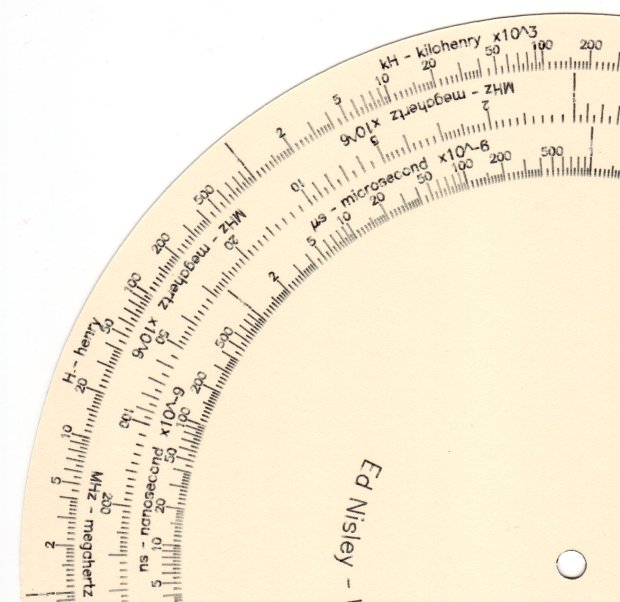
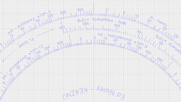
The Tektronix Circuit Computer, being a specialized circular slide rule, requires logarithmic scales bent around arcs:
Scale Tick Layout – Bottom Deck
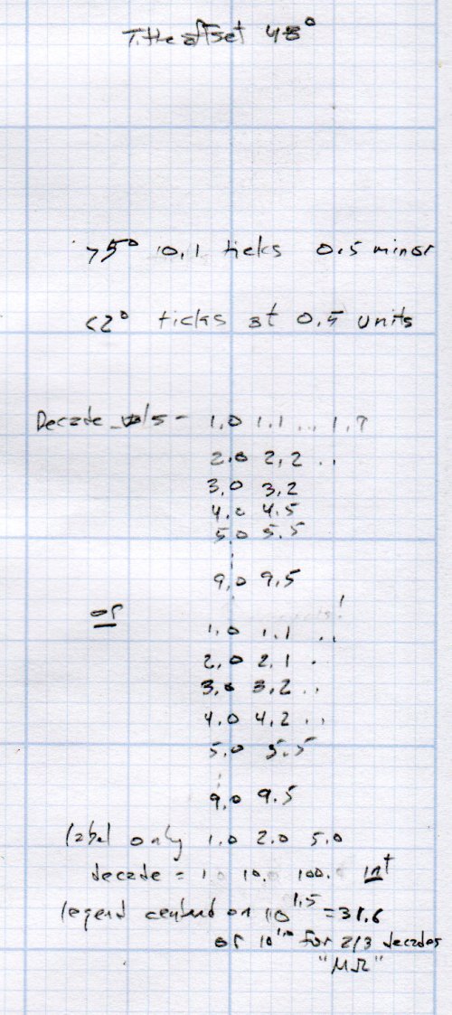
Each decade spans 18°, except for the FL scale’s 36° span to extract the square root of the LC product:
FL = 1 / (2π · sqrt(LC))
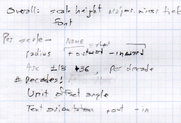
The tick marks can point inward or outward from their baseline radius, with corresponding scale labels reading either inward or outward.
There being no (easy) way to algorithmically set the tick lengths, I used a (pair of) tables (a.k.a. vector lists):
TickScaleNarrow = {
  [1.0,TickMajor],
  [1.1,TickMinor],[1.2,TickMinor],[1.3,TickMinor],[1.4,TickMinor],
  [1.5,TickMid],
  [1.6,TickMinor],[1.7,TickMinor],[1.8,TickMinor],[1.9,TickMinor],
  [2.0,TickMajor],
  [2.2,TickMinor],[2.4,TickMinor],[2.6,TickMinor],[2.8,TickMinor],
  [3.0,TickMajor],
… and so on …
The first number in each vector is the tick value in the decade, the log of which corresponds to its angular position. The second gives its length, with three constants matching up to the actual lengths on the Tek scales.
The Circuit Computer labels only three ticks within each decade in the familiar (to EE bears, anyhow) 1, 2, 5 sequence. Their logs are 0.0, 0.3, and 0.7, spacing them neatly at the 1/3 decade points.
Pop quiz: If you wanted to label two evenly spaced ticks per decade, you’d mark 1 and …
Generating the L (inductance) scale on the bottom deck goes like this:
The L scale covers 1 nH to 1 MH (!), as set by the MinLog and MaxLog values. Arc sets the angular size of each decade from ScaleArc, with the negative sign indicating the values increase in the clockwise direction.
The first decade starts with a tick labeled 1, so dec = 1. The next decade has dec = 10 and the third has dec = 100. Maybe I should have used the log values 0, 1, and 2, but that seemed too intricate.
The angular offset is zero because this is the outermost scale, so 1.0 H will be at 0° (the picture is rotated about half a turns, so you’ll find it off to the left). All other scales on the deck have a nonzero offset to put their unit tick at the proper angle with respect to this one.
The scales have legends for each group of three decades, positioned in the middle of the group:
I wish there were a clean way to draw exponents, as the GCMC Hershey font does not include superscripts, but the characters already live at the small end of what’s do-able with a ballpoint pen cartridge. Engraving will surely work better, but stylin’ exponents are definitely in the nature of fine tuning.
With all that in hand, the scales look just like they should:
This file contains hidden or bidirectional Unicode text that may be interpreted or compiled differently than what appears below. To review, open the file in an editor that reveals hidden Unicode characters.
Learn more about bidirectional Unicode characters
This file contains hidden or bidirectional Unicode text that may be interpreted or compiled differently than what appears below. To review, open the file in an editor that reveals hidden Unicode characters.
Learn more about bidirectional Unicode characters
This file contains hidden or bidirectional Unicode text that may be interpreted or compiled differently than what appears below. To review, open the file in an editor that reveals hidden Unicode characters.
Learn more about bidirectional Unicode characters
The text baseline sits at the specified radius from the center point, regardless of its orientation, so you must offset the text path by half its height in the proper direction before handing it to the ArcText function.
A utility function to draw scale legends stuffs some of that complexity into a bottle:
function ArcLegend(Text,Radius,Angle,Orient) {

  local tp = scale(typeset(Text,TextFont),LegendTextSize);
  local tpa = ArcText(tp,[0mm,0mm],Radius,Angle,TEXT_CENTERED,Orient);

  feedrate(TextSpeed);
  engrave(tpa,TravelZ,EngraveZ);
}
Which means most of the text uses a simpler invocation:
Arc determines the angular span of each decade, with positive values going counterclockwise. MinLog is the logarithm of the scale endpoint, so adding 1.5 puts the text angle one-and-a-half decades from MinLog and multiplying by Arc moves it in the right direction. The offset angle rotates the entire scale with respect to the 0° reference sticking out the X axis over on the right. The top picture has its 0° reference pointing north-northeast.
The GCMC source code as a GitHub Gist:
This file contains hidden or bidirectional Unicode text that may be interpreted or compiled differently than what appears below. To review, open the file in an editor that reveals hidden Unicode characters.
Learn more about bidirectional Unicode characters
GCMC treats variables defined inside a function as local, unless they’re already defined in an enclosing scope, whereupon you overwrite the outer variables. This wasn’t a problem in my earlier programs, but I fired the footgun with nested functions using the same local / temporary variables. Now, I ruthlessly declare truly local variables as local, except when I don’t, for what seem good reasons at the time.
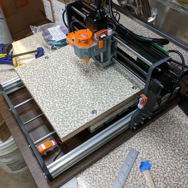
The CNC 3018-Pro uses cheap & readily available parts, so extending the Y axis went smoothly:
CNC 3018-34 – overview
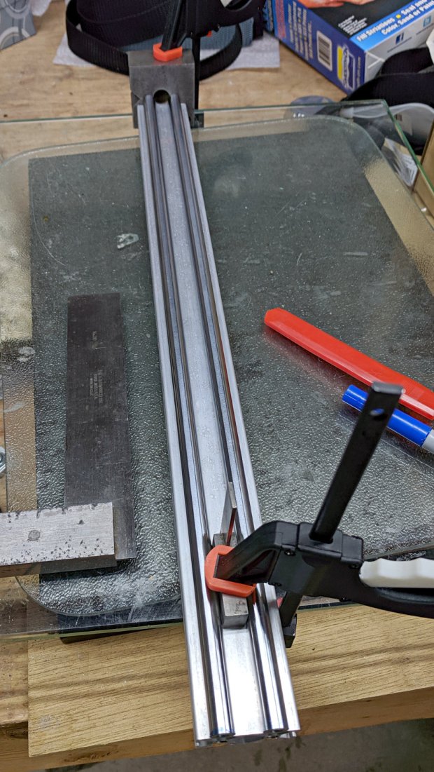
The 2040 side rails are now 450 mm long, as is the 8 mm leadscrew. I ordered 500 mm guide rods to forestall small length mismatches, then marked them to match the rails:
CNC 3018-ProXL – marking guide rods
Cut them off slightly beyond the mark, face the raw ends to length, drill-and-tap for M5 screws, then put a pair of just-under-50-mm stubs in the bar stockpile. They ought to come in handy for something, right?
The original side rails & guide rods were 290 (not 300!) mm long, so the table gained another 160 mm of travel for a total of 340 mm; I suppose it’s now a CNC 3034-Pro. Seeing as how it’s the only one and I don’t want to kill my snicker SEO, let’s call it a CNC 3018-ProXL or a maybe 3018-Pro34. Whatever.
The embiggened 300×340 mm platform dates back to the original 1955 kitchen: genuine Formica over plywood. It sits atop the previous 300×180 mm table, now demoted to being a riser, and a sheet of closed-cell foam, with the same 50 mm long M6 screws holding everything to T-nuts in the 3018’s original aluminum platform.
And, yes, the identical Formica underneath the machine originally covered a freestanding kitchen cabinet; I knew I kept it around for some good reason. Kinda disorienting to see a piece of the pattern moving against the same background, though.
The GRBL setup now extends the Y-axis length ($131=338) and puts the G54 coordinate at the new middle, with the Z-axis origin kissing the ball-point pen on the new surface:
G10 L2 P1 X-145 Y-169 Z-24.6
While I was at it, I set the G28 position at the far left side of the gantry, with the table sticking out to the front, and the Z axis at the top:
G28.1 X-298 Y-1 Z-1
Those are absolute machine coordinates, with Y and Z pulled off home by 1 mm. I set one of bCNC’s buttons to emit G28 and park the tool carrier over there, out of the way.
With all that prepared, a full-size Tek Circuit Computer disk plots the way it should on a sheet of Letter-size paper:
CNC 3018-34 – first light
I suspect the longer rods wouldn’t work quite so well for actual milling / machining any material tougher than, say, rigid foam blocks. For engraving and pen plotting, they’re all good.
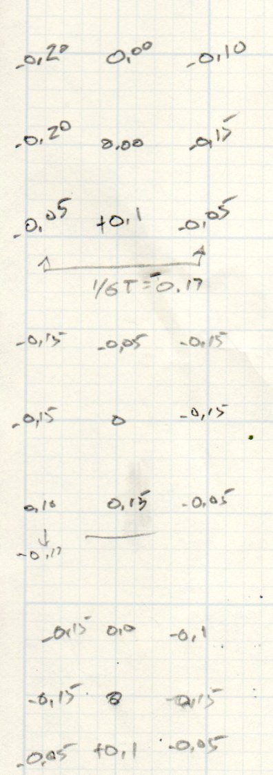
Some measurements show this countertop isn’t quite as flat as the previous one, but a pair of tweaks got it within -0.15 / +0.1 mm:
CNC 3018-ProXL – table flatness – 2019-11-09
Which I defined to be Good Enough™ for use with spring-loaded implements of cutting & drawing.
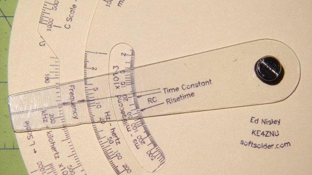
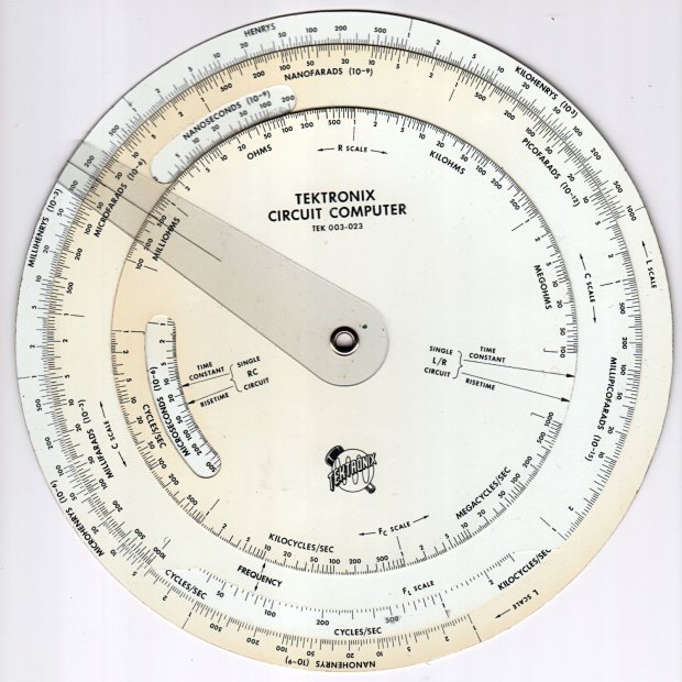
Following a linkie I can no longer find led me to retrieve the Tektronix Circuit Computer in my Box o’ Slide Rules:
Tektronix Circuit Computer – front
I’m pretty sure it came from Mad Phil’s collection. One can line up the discolored parts of the decks under their cutout windows to restore it to its previous alignment; most likely it sat at the end of a row of books (remember books?) on his reference shelf.
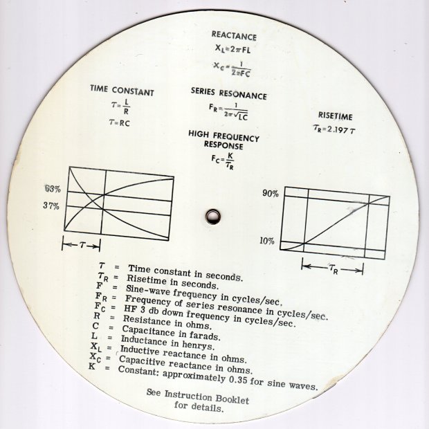
The reverse side lists the equations it can solve, plus pictorial help for the puzzled:
Tektronix Circuit Computer – rear
Some searching reveals the original version had three aluminum disks, shaped and milled and photo-printed, with a honkin’ hex nut holding the cursor in place. The one I have seems like laser-printed card stock between plastic laminating film; they don’t make ’em like that any more, either.
TEK PN 003-023 (the paper edition) runs about thirty bucks (modulo the occasional outlier) on eBay, so we’re not dealing in priceless antiquity here. The manual is readily available as a PDF, with photos in the back.
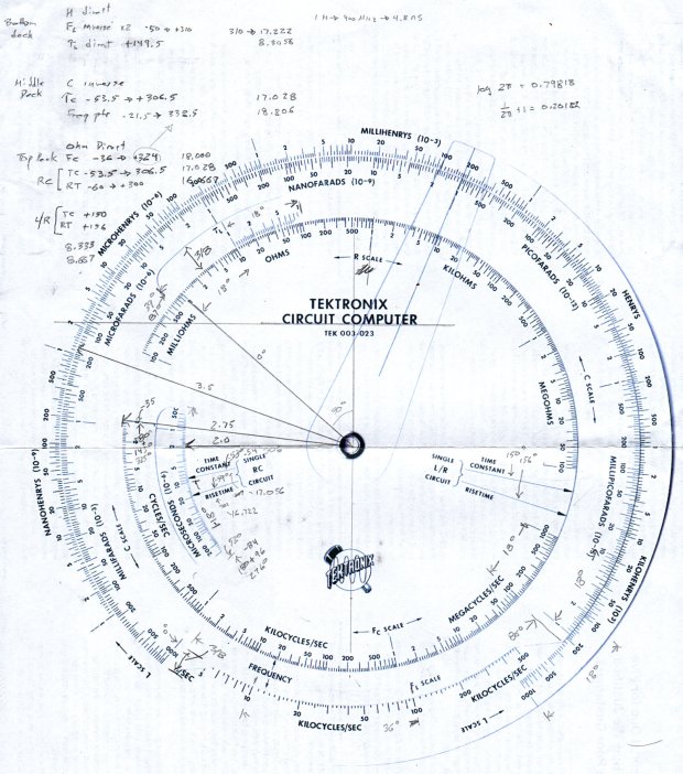
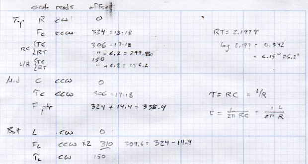
Some doodling produced key measurements:
Tektronix Circuit Computer – angle layout
All the dimensions are hard inches, of course.
Each log decade spans 18°, with the Inductive Frequency scale at 36° for the square root required to calculate circuit resonance.
Generating the log scales requires handling all possible combinations of:
Scales increase clockwise
Scales increase counterclockwise
Ticks point outward
Ticks point inward
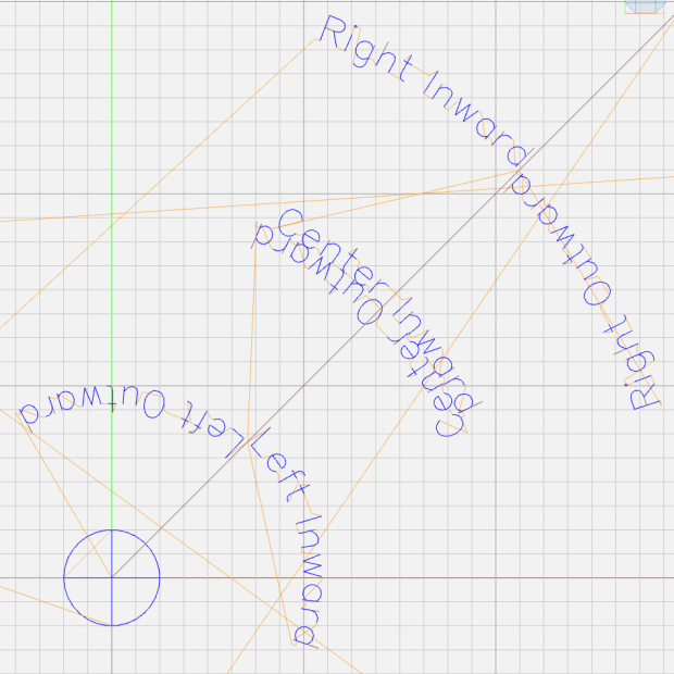
Text reads from center
Text reads from rim
I used the 1×100 tick on the outer scale of each deck as the 0° reference for the other scales on that deck. The 0° tick appears at the far right of plots & engravings & suchlike.
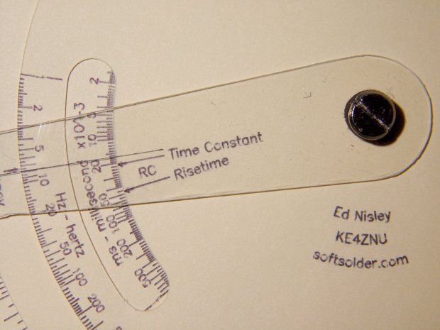
The L/R Time Constant (tau = τ) pointer on the top deck and the corresponding τL scale on the bottom deck has (what seems like) an arbitrary -150° offset from the 0° reference.
The Inductive Frequency scale has an offset of 2π, the log of which is 0.79818 = 14.37°.
The risetime calculations have a factor of 2.197, offsetting those pointers from their corresponding τ pointer by 0.342 = log(2.197) = 6.15°.
A fair bit of effort produced a GCMC program creating a full-size check plot of the bottom deck on the MPCNC:
By the conservation of perversity, the image is rotated 90° to put the 1 H tick straight up.
The 3018 can’t handle a 7.75 inch = 196 mm disk, but a CD-size (120 mm OD) engraving came out OK on white plastic filled with black crayon:
Tek CC bottom – ABS 160g 2400mm-min
The millimeter scale over on the right shows the letters stand a bit under 1 mm tall. And, yes, the middle scale should read upside-down.
Properly filling the engraved lines remains an ongoing experiment. More downforce on the diamond or more passes through the G-Code should produce deeper trenches, perhaps with correspondingly higher ridges along the sides. Sanding & polishing the plastic without removing the ink seems tedious.
The Great Dragorn of Kismet observes I have a gift for picking projects at the cutting edge of consumer demand.
More doodles while figuring the GCMC code produced a summary of the scale offsets:
It turned out easier to build vectors of tick mark values and their corresponding lengths, with another list of ticks to be labeled, than to figure out how to automate those values.
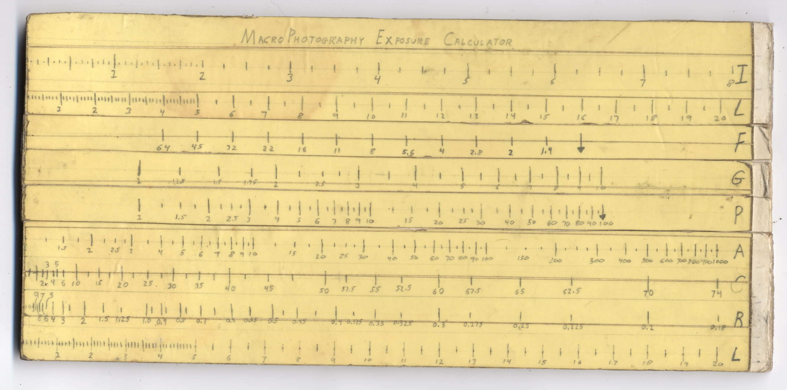
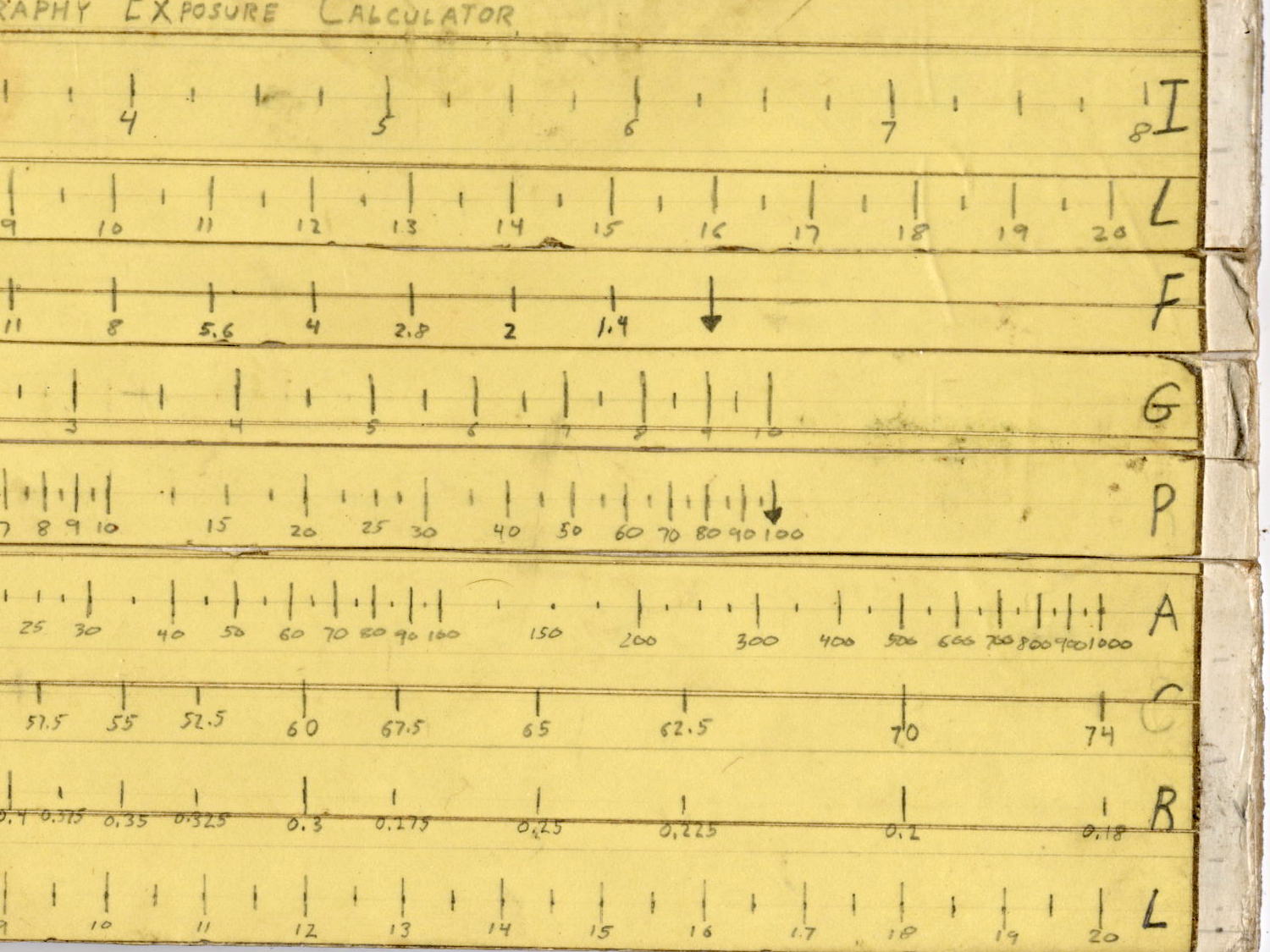
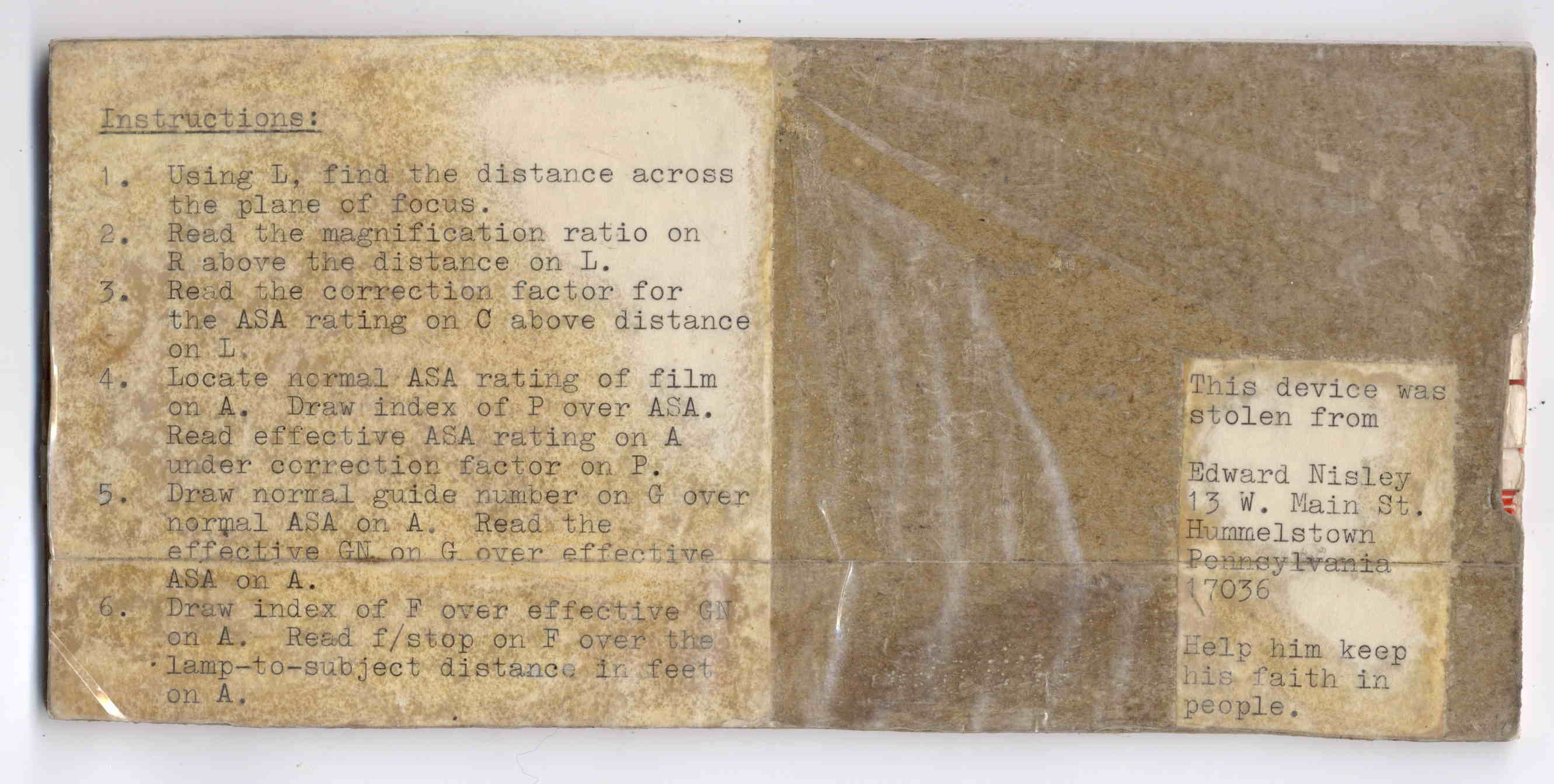
Back in high school, I designed and built a slide rule exposure calculator to improve my macro photographs:
Macrophotography Exposure Calculator – front
The base consists of three layers of thin cardboard glued together with Elmer’s Glue. The three slides have three layers of thinner white cardboard glued together, with offsets forming tongue-and-groove interlocks, topped with yellow paper for that true slide rule look:
Judging from the seams, I covered the hand-drawn scales with “invisible” matte-surface Scotch Tape. Worked well, if you ask me, and still looks pretty good:
Macrophotography Exposure Calculator – front – detail
The reverse side carries instructions under a layer of packing tape (which hasn’t survived the test of time nearly as well), for anyone needing help:
The slides still move, albeit stiffly, and it might be usable.
I vaguely recall extension tubes on an early SLR, but memory fades after that. Getting the exposure settings close to the right value evidently posed something of a challenge and, given the cost of 35 mm film + development, it made sense to be careful.
Fortunately, even today’s low-end cameras make macro photography, at least for my simple needs, easy enough, with the camera handling the exposure calculations all by itself:
“… One of the most frightening things about your true nerd, for many people, is not that he’s socially inept — everybody’s been there — but rather his complete lack of embarrassment about it.”
“Which is kind of pathetic.”
“It was pathetic when they were in high school,” Randy says. “Now it’s something else. Something very different from pathetic.”
“What, then?”
“I don’t know. There is no word for it. You’ll see.”