Ed Nisley's Blog: Shop notes, electronics, firmware, machinery, 3D printing, laser cuttery, and curiosities. Contents: 100% human thinking, 0% AI slop.
The Totally Featureless Clock will have a black acrylic case with a Graylite Lexan faceplate. The top & bottom panels are 11.75 inches long, which is much too large for the Sherline’s 9-inch maximum X travel.
Fortunately, in this case I can cheat.
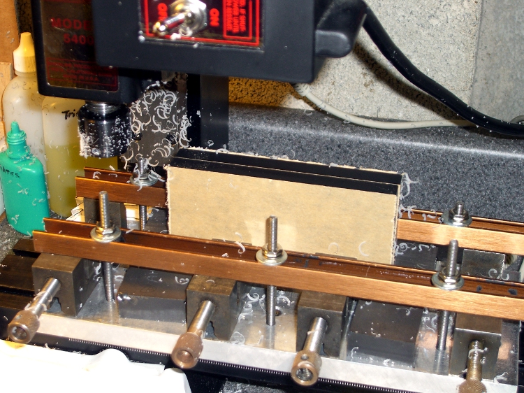
This setup cut the panels to the proper width. A pair of parallel blocks, made from some mysterious glass-like material and ground very nicely flat, support the panel just over the body of the four toolmaker’s vises lined up along the tooling plate. I drilled the brown bookshelf rails to match the tooling plate and secured them with 10-32 studs.
The front rail secures the vise bodies to the tooling plate; they’re aligned parallel to the X axis by the simple expedient of laying a parallel along the back edge and matching that to the tooling plate. No real precision is in order here; the flycut is across the whole top edge.
The rear rail holds the movable vise jaws down; they tend to rise up just slightly when tightened, but the difference amounts to barely enough to release pressure on the parallel blocks. Not enough to matter, as it turned out.
The general notion is to flycut about 2/3 of the length of the panel, then slide it far enough to cut the remainder. Flip it over and flycut the other side the same way.
About 1000 rpm and 150 mm /min, cutting 0.5 mm or so on each pass.
This worked surprisingly well. I expected to find a bow in the middle due to an uneven bandsaw cut on the initial downward side, but it was all good; evidently the blocks were wide enough to average things out.
The joint where the two cuts meet turns out to be visible, but barely detectable with a fingernail: entirely suitable for this application. I’ll hit the sides with sandpaper on a sheet of plate glass before bonding them to the faceplate.
Flycutting the end panels was much simpler: one pass clears their entire length. I moved the clamping rails to simplify the whole process; turned out that clamping the movable jaw didn’t really gain very much at all while complexicating the slide-the-stock process beyond belief.
Flycutting end panels
Overall, the width varies by about two mils along the length of the long panels and they’re perfectly straight as measured against a surface plate. Definitely close enough!
What with all the milling going on lately, I decided to replace the crusty bellows on the Sherline mill. The previous design worked reasonably well, but I’ve had a few tweaks in mind for a while.
Color coded lines so you know which way to fold them!
Unlined side up for a neat look
Fits on Letter and A4 sheets
Taping cuts and hints
The PDF page size is about 8×10 inches; call it 204×280 mm. Print it without scaling and it should just barely squeak onto the sheet. If you don’t have a full-bleed printer, the tips of the sides may get cropped off, but you can extrapolate easily enough.
Some assembly required:
Cut it out
Fold the central valleys (red) first, flatten it out again
Fold the central ridges (blue) next
Pleat the whole thing into a half-inch tall stack
Squash it into a neat package to harden the folds
Fold the tips along one side
Fold the tips along the other side
Squash the folds again
Make the saddle cuts & fold the tabs
Apply double-stick tape as noted (some on back)
Install on your cleaned-up mill
Admire!
The tip folding is the trickiest part. Basically, flip the first tip from a ridge to a valley, then chase the little transition folds into place. Repeat for each tip along that side, then do the other side.
It gets easier after you fumble around for a while.
My nimble-fingered daughter has offered to fold ’em for you. Stick a few bucks in an envelope and mail it to me; we’ll mail back two folded sets (two each, front and rear bellows) for your amusement. Kid’s gotta earn her college money somehow…
Address? Go to the QRZ.com database and search for my amateur radio callsign: KE4ZNU. Cut, paste, that was easy.
For the do-it-yourselfers, start with the PDF file in the link above. That’s the easiest way to get the correct scaling. The tabs on the ends should be 4.0 inches across on the printed page.
Rear BellowsFront Bellows
Here are some 300 dpi PNG files, but you’re on your own for scaling.
If you want the original Inkscape SVG files, drop me a note.
I needed a few strips of single-row pin headers, but the parts bin was empty.
I hate it when that happens.
The heap disgorged a handful of double-row strips and, of course, I Have A Machine Shop.
So: no problem.
This is, I admit, not cost-effective, but it took about 15 minutes to slit the aforementioned handful of strips right down the middle and get back to soldering.
The trick is to use an ultra-thin slitting saw, rather than a regular saw. The one here is 4 mils thick and the better part of 7/8″ in diameter; call it 0.1 mm x 22 mm. I think it came with one of the Dremel tool kits a long while ago.
Cut about 1 mm deep on the first pass, then cut through on the return to avoid having the saw deflect too much. Run about 100 mm/min, 1000 rpm, and no coolant. Line it up by eye, type manual CNC commands into EMC2, and it’s all good.
The trick is finding a mandrel that doesn’t collide with the vise; my larger saws have a rather thick screw-and-washer arrangement that doesn’t fit. I think some padding (chopped-up credit cards?) between the longer pins, mounting the vise vertically, and grabbing the longer pins would fix that. The catch might be clearance between the top of the vise and the bottom of the spindle motor.
Better to just buy some single-row strips. Sheesh… but if all you have is a CNC mill, you have plenty of solutions.
I use a blender to mix up the pancake batter every few days. Over the last week or so, the rotary switch Pulse position wasn’t returning to Off all by itself. After having replaced the impeller bearings, I couldn’t just ditch the mumble thing without at least trying to fix it…
A search for replacement parts reveals that Farberware kitchen appliances are disposable crap: they’re so cheap nobody stocks repair parts. IIRC, this blender was maybe ten or twenty bucks after rebate, which gets you through the shipping charge for the repair part. I would love to believe that paying more for kitchen appliances actually bought better quality.
Switch wire connections
As you’d expect, the four silicone rubber feet pop off to reveal machine screws that hold the plastic base to the metal body. This picture shows the wire connections to the switch:
L = brown
1 = orange
2 = no connection
3 = red
I couldn’t pull the switch knob off the shaft, so I dismantled enough of the motor mount to ease it to one side, apply a right-angle screwdriver to the switch body screws, and loosen the switch. That gave me enough room to jam a screwdriver between the switch and the mounting bracket to pry the knob off. It’s a plastic-on-plastic friction fit.
After the fact, it turns out that two screws behind the knob secure the mounting bracket to the bezel. Remove those screws, the bracket comes off, and it’s trivially easy to remove the switch screws.
The wires attach through those horrible spring-loaded push-and-pray connections: jam the wires in, pull back, and it’s supposed to be a gas-tight joint forever. I don’t believe a word of it. Remove the wires by poking a small screwdriver into the opening and forcing the brass tab away from the wire. Yuch!
Opening switch with slitting saw
The switch body parts are, of course, bonded firmly together: no user serviceable parts inside. I deployed a slitting saw on the Sherline mill, grabbed the switch in the vise, and sliced 2.5 mm deep along the line between the two body parts.
The switch is some sort of engineering plastic, so I ran the saw at about 2000 rpm, cut at 100 mm/min, and dribbled water on the blade to keep it cool. You can see the grayish-brown residue under the switch.
The thing came apart easily enough after that…
Switch Guts
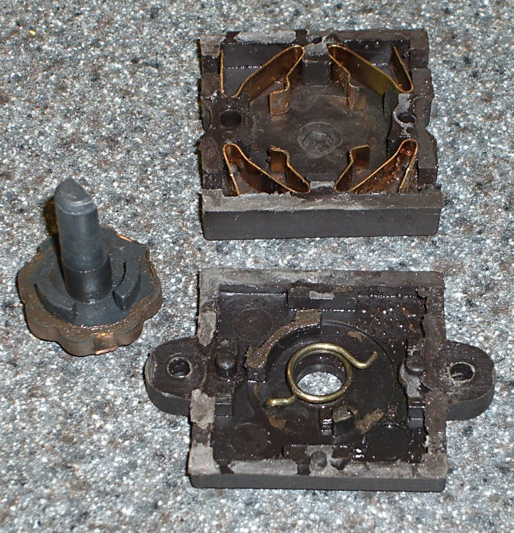
These pics show the switch components. Note how the spring fits in the body and the four cunningly folded brass strips that simultaneously attach the wires, make the switch contacts, and spring-load the rotary detents.
I took the liberty of bending the strips to restore the clamping force on the wires; poking the tabs with a screwdriver tends to bend them a bit.
So it goes.
There wasn’t anything obviously wrong inside, but after a bit of puzzling, I discovered the problem residing in the coil spring that returns the switch to Off…
Cracked spring
The spring wire is 1 mm diameter. A bit of rummaging in Small Spring Box Number Two disgorged a bag of spring-clip thingies with the proper wire size and just about the right coil diameter, too.
The right way to make a spring is to start with straight music wire, anneal it, make a mandrel, bend up a spring, then heat-treat the spring to make it just the right hardness and toughness for the job.
Spring iterations
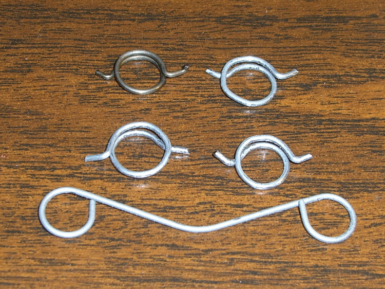
I deployed my wire-bending pliers, made a few trial runs (well, OK, they weren’t trial runs when I started…), and got close enough by the third attempt (lower right).
Yup, cold-bending spring steel. It is to shudder, huh?
I bent the wire just off straight and worked my way around the coil about 0.5 mm per bend to produce a rather lumpy coil spring. This is definitely the wrong way to go, because the wire’s much too hard for that treatment: it wants to stay straight and doesn’t like those right-angle bends to form the end tabs. I think this will work well enough for long enough, though.
The spring’s chirality turns out to be important; the coil wants to tighten around the shaft when the knob’s in the Pulse position. The spring-clip thing has two ends; only one produces the correct result, which is perfectly obvious in retrospect.
Spring on switch rotor
The spring fits on the rotor like this, but with a whole lot more preload tension than you’d expect. The end result was a somewhat smaller coil diameter than I started with; I shrank the coil, re-bent a new tab on one end, chopped off about 4 mm of wire, and it was all good.
I also backed off the ramp on the notches that engage the brass contacts in the Pulse position so the switch wasn’t so prone to hang up. That was what motivated me to fix the thing: one morning I manged to leave the switch in Pulse because it didn’t quite snap back to Off, took the lid off the bowl, and the blender started up again. Fortunately, the batter is too thick to jump out of the bowl, but it was a near thing.
Here are the four switch positions and their contacts, in order from Pulse (most counterclockwise) to Speed 2 (most clockwise). You could, I suppose, conjure up a replacement switch if you puzzled out the connections; all the rotor tabs are connected together.
Switch contacts – PulseSwitch contacts – Off
Notice that, although switch contact 2 is unused, it is connected when the switch is in the Off position.
The back of the switch body takes pressure on the switch knob, as well as engaging the end of the rotor to hold it in the middle of the body. I wasn’t comfortable just gluing the body together again, because I suspect none of my adhesives will actually bond to the plastic.
So I chopped off a length of aluminum U-channel, poked two holes it in, shortened a pair of salvaged screws, and made a clamp for the switch body’s back. The body has three locating pins, so the two parts aren’t shifting with respect to each other, and the clamp holds the back firmly in position.
Repaired switch with back clamp
Reassembly is in reverse order, paying a bit of attention to securing the wires in those crappy push-and-pray contacts and keeping everything away from the cooling fan as the bottom snaps into place.
Done!
The economics of this sort of repair make absolutely no sense at all, but I hate throwing stuff away just because some cheap part failed. In this case, I’d be happy to replace the switch… let me know where you can find one with the requisite contacts and spring arrangement!
It turns out that attaching some, but not all, of the PCs around here to the Arduino Pro board controlling the Totally Featureless Clock cause the WWVB receiver to drown in a sea of noise. In fact, just touching the USB cable’s shield to the FTDI Basic USB-to-serial adapter would bring the noise.
So this is a quick-and-dirty circuit to see if optical isolation will reduce the problem enough to be bearable.
The schematic is pretty simple: two bits in, two bits out.
Optical Isolate Schematic
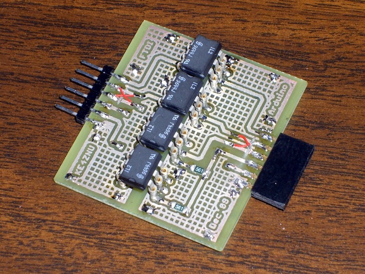
The layout puts the DIP isolators on the top and the SMD resistors on the bottom. I used fancy screw-machine IC socket pins, just because I had some, but you could solder the isolators directly to the board. The FTDI Basic connects through header pins and the Arduino connects through female header sockets, both soldered sideways to the top of the board. I’ll eventually reinforce them with some epoxy, never fear.
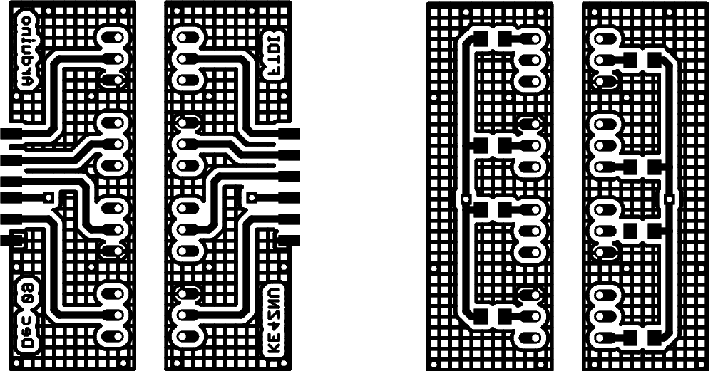
Double-size PCB layout:
PCB Layout
Actual-size copper images. Remember that the top copper is flipped left-to-right here so it comes out properly after toner-transfer imaging.
Copper
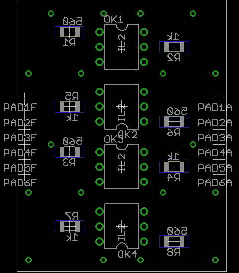
And the placement info showing where the parts wind up. This is sort of the silkscreen for the top and bottom, both together: the backwards stuff goes on the bottom side.
Top and Bottom Silkscreen
The alert reader will note that the photo doesn’t match the rest of the images. Nay, verily, eagle-eyed readers will have picked out a few resistors on the top and two embarrassing little red-wire Xes at the connectors. Somehow, I managed to swap the RxD and TxD pins, even with an FTDI board on the desk next to me. I hate it when that happens… so I fixed the schematic & layout for the next time around.
The resistors push a lot of current through the LEDs and phototransistors, which is what you need to get decent 19200 b/s serial data pulses. Here’s what the data stream out of the TxD isolator looks like:
Optoisolator – TXD
I have the Eagle files and the CNC drill file for my Sherline mill if you must have them, but you can go from those images above directly to the hardware. It’s an evening’s work, more or less.
You might want to kludge a jumper into the Reset line so it’s impossible to accidentally reset the Arduino. Sometimes you don’t want a reset, like after a few days of data collection…
Now, does it actually do what I expected? The early reports are good, but I’m at the mercy of the atmosphere and must collect a few days (actually, nights) worth of data to find just how far down the noise went.
I needed a brass tube with a lengthwise slit to serve as an electrostatic shield around a ferrite bar antenna. There are many wrong ways to do this, all of which produce terrible results, pose a serious risk of personal injury, or both. I say that with some confidence, having tried some of them over the years.
Here’s one right way: fill the tube with Wood’s Metal, thus turning it into a solid rod, then cut the slit with a slitting saw.
Wood’s Metal is a moderately toxic alloy that melts in hot water, which turns casting into a simple workbench operation. You might not want to cast it in the kitchen, but that’s your call. Clean up the scraps, wash the counter even though you used newspaper, wash your hands, and don’t suck your thumb.
As shown, I just poured the molten metal into the brass tube atop a steel block, broke off whatever seeped out, and remelted the scraps. Turns out I had just barely enough for the job.
Slitting brass tubing – overview
My buddy Eks gave me a stack of slitting saws a while ago and I modified a standard Sherline holder to fit them. Turns out there’s just barely enough room for everything within the mill’s working envelope; the saws are a bit over 3 inches in diameter.
So I cut the back of the tubing, making the pictures somewhat disorienting.
The tubing fit neatly into an old V-block (evidently homebrewed by a better machinist than I), held down by ordinary Sherline clamps on perilously long studs screwed into the tooling plate. The saw had just enough reach to clear the rather broad V-block’s shoulder.
The tubing is 0.630 OD with a 15-mil wall and the saw blade is pretty nearly 32 mils thick. I touched off Z=0.331 (630/2 + 32/2) with the blade atop the tubing, then jogged away to Y=+1 and drove down to Z=0 to cut exactly through the middle of the tube.
Slit 0.015 inch deep
The V-block is aligned with the front of the table, but I did a bit of nudging to persuade it into final alignment. Of course, the saw wasn’t quite centered on the holder, so a blade or three tinged on the tubing when I did a Y=0 trial pass at low RPM.
For lack of anything smarter, I cut at 500 RPM and fed at 5 inch/min. That’s painfully slow, but correspondingly boring… remember, in machine shop work, boring is good.
I did five passes: one trial at Y=0, three cuts at 5-mil steps, and a cleanup cut. The picture shows the 15-mil pass left a very thin web at the far end. A final 2-mil cut removed that web, leaving only a few burrs. You could do it in one pass, but I wanted to minimize the depth-of-cut into the Wood’s Metal.
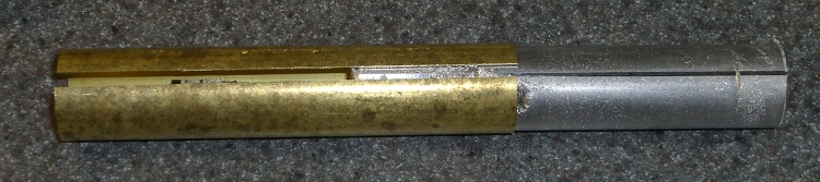
Unclamp, discover that the cast metal rod slides right out, touch up the edges with a file, and it’s all good. A lovely slit, perfectly aligned, without bent metal or bloodshed.
As a bonus, I get a nice Wood’s Metal ingot out of the operation. The line along the rod is just barely perceptible with a fingernail; it’s more of a polished line than an actual cut.
Slit tube with Wood's Metal ingot
Turns out the shield works a bit too well: it cuts out the WWVB signal, too. I think the tubing is too close a fit to the ferrite rod and detunes the winding. More experimentation is in order…
I use the Standard edition of Cadsoft’s EAGLE schematic capture & PCB layout program, which puts a 160×100 mm upper limit on circuit boards. That meshes nicely with the capabilities of my Sherline CNC mill, which I use to drill component holes.
I’m currently making a set of PCBs that are pretty close to that maximum size. They’re awkward to clamp, difficult to peel off from double-sided tape, and require careful positioning to ensure they don’t hit the mill column. Been there, done that, time for something better.
The simple acrylic sheet platen shown here seems to work well. The PCB is a 5×8-inch sheet, clamped along three sides with some aluminum U-channel from the heap. That’s why two of the rails have random holes: it came pre-drilled for something else.
Platen with 5×8-inch PCB
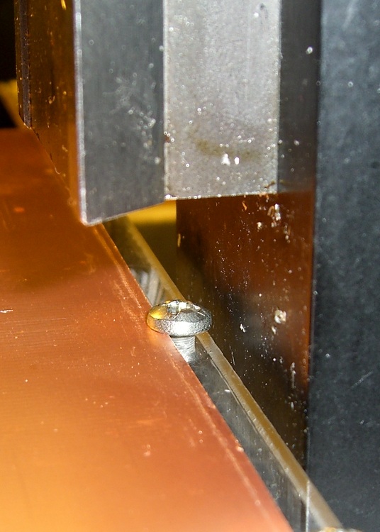
The rear edge (closest to the mill column) has three screws that serve multiple purposes:
They clamp the edge of the sheet firmly to the platen
The two end screws protrude through the platen and align it along the rear edge of the mill table
The middle screw is an origin alignment marker
Rear clearance
My mill has slightly less than the absolute maximum Y-axis travel because I added a bushing to capture the end of the leadscrew, as described there. The picture shows the clearance between the back of the platen and the mill column: 2 mm, more or less. The 6-32 screw head is flush with the rear edge of the platen.
Alignment along the Y-axis is easy: jog rearward until the stepper motor stalls, ease away a smidge, then touch off at Y=3.8 inches. Stalling the motor is bad practice with servos or husky steppers, but on this sort of low-power machine it’s perfectly OK. (One could argue for limit switches, but in vain.)
Slap the platen on the mill table tooling plate (turns out that the Z-axis reach is marginal for the shortest carbide drill when it’s in a collet, oops), adjust more-or-less to the middle of the X-axis scale on the front of the table, line up the hold-down clamps, then crunch the U-channels down on the circuit board. That holds everything in place very firmly; the front overhang doesn’t get much torque because the mill can only reach 4 inches from the rear edge, just beyond the mill table underneath.
That center screw is eyeballometrically in the middle of the platen’s width, so X-axis alignment is also easy: put the laser dot (visible in the top picture if you squint) on the near-side edge of the screw and touch off X=3.2 inches.
That alignment puts the X=Y=0 origin at the front-left corner, about 1/4″ in from the left-side clamp and an inch behind the front clamp.
The mill’s X axis reach goes beyond the clamps, but the 160 mm = 6.30 inch extent of an EAGLE board fits neatly inside.
The Y-axis reach is barely over 3.8 inches, just shy of EAGLE’s 100 mm = 3.94 inches, but that’s close enough for what I need to do. Getting that last 0.14 inch would require a very, very thin clamp at the rear, minus the Y-axis bushing. There wouldn’t be much clearance from the holes to the edge of the board, either.
The generous Y-axis clearance on the front allows for the trickery needed to run toner-transfer sheets through the fuser; you want margins all around the drilled area. More about that there, plus search for PCB to unearth other posts.
Remember that the way I make PCBs, the holes act as alignment points for the toner transfer sheet. That means I don’t really care about absolute alignment with respect to the raw PCB sheet: just clamp it down and start drilling.