The Smell of Molten Projects in the Morning

Ed Nisley's Blog: Shop notes, electronics, firmware, machinery, 3D printing, laser cuttery, and curiosities. Contents: 100% human thinking, 0% AI slop.

Tag: Sherline

Sherline CNC mill

  • Plug Alignment for ICOM IC-Z1A Radio

    Plugs and jack alignment plates
    Plugs and jack alignment plates

    As I mentioned there, I originally connected my bicycle-mobile amateur radio gadget to the ICOM IC-Z1A radio using separate mic and speaker plugs. That seemed like a good idea, but bicycles vibrate a lot and the plugs apply enough leverage to the jacks inside the radio to pry them right off the PCB. That requires a protracted repair session that I never wanted to do again.

    The solution is to mount both plugs rigidly on the radio so that they simply can’t move. I dithered for a while and finally decided that function trumps good looks on this project, particularly given that our radios spend their entire lives inside a bag behind the bike seats.

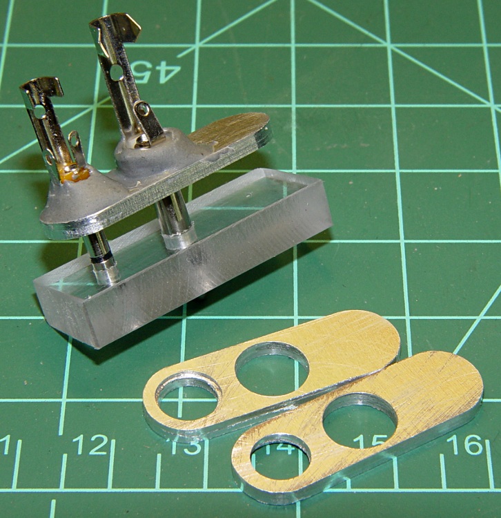
    The top picture shows the small aluminum plates I made to align the plugs to the HT jacks, along with a plastic gluing fixture to hold the plugs parallel while the epoxy cures. If you just jam the plugs into the radio without an alignment fixture, you will glue the plugs together in such a way that they cannot be removed: the radio does not hold the shafts exactly parallel!

    Plug stabilization - What Not To Do
    Plug stabilization – What Not To Do

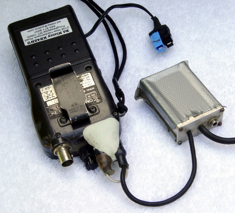
    How do I know? Well, I tried doing exactly that by simply epoxying the existing plugs into place, applying enough epoxy putty to stabilize the plugs against the radio. Looks reasonable, but when it came time to take them out (and you will want to take them out, trust me) they are firmly and permanently embedded. I had to carve them apart to get them out.

    The mic, speaker, and coaxial power jacks are 10 mm on center. The 2.5 mm mic plug has a small shoulder that required a matching recess in the plate, while the 3.5 mm speaker plug is basically a cylinder. I don’t use the coaxial power jack, having hacked an alkaline battery pack with Anderson Powerpoles. The plate’s external contour matches the flat area atop the radio around the jacks.

    You could lay out and drill close-enough holes by hand, use a step drill to make the shoulder recess, and then let the epoxy do the final alignment. However, you want the center-to-center distance exactly spot-on correct, as the plugs won’t mate properly otherwise. I turned it into a CNC project for my Sherline mill, of course, but that’s just because I have one.

    HT Plugs in gluing fixture
    HT Plugs in gluing fixture

    This picture shows two plugs epoxied into the plate. While the epoxy cures, the plate rests atop the fixture with the two plugs vertical and their shell flanges flush against it. I applied the epoxy with a toothpick and worked it into the gap between the threads and the plate.

    The end result will be a pair of plugs that exactly match the radio’s jacks in a plate that sits firmly atop the radio’s case. You should find that the plugs snap firmly into place and the entire assembly is absolutely rigid.

    Caveat: don’t use an aluminum plate if your radio depends on separate electrical connections for the mic and speaker plug shells. The IC-Z1A has isolated shells, but remains happy when they’re connected. My Kenwood TH-F6A HT uses the shells for entirely different functions and will not work with them shorted together.

    With the epoxy cured, wire the connections as usual. I had a small cable with enough tiny wires to put the mic conductors in their own shielded pair, but that’s likely overkill.

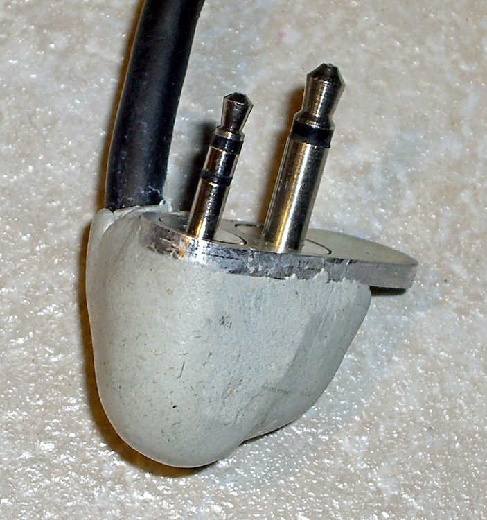
    Finished plugs with epoxy blob
    Finished plugs with epoxy blob

    You could machine a nice enclosure, but I simply molded an epoxy putty turd around the connections, shells, and cable. The trick is to wait until it’s nearly cured, plug it into the radio, then shave off whatever gets in the way of the knobs, antenna plug, and other appurtenances.

    It may not look elegant, but it works great!

  • Avid Rollamajig Repair

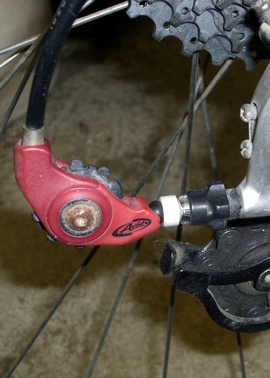
    Avid Rollamajig with new ball socket
    Avid Rollamajig with new ball socket

    Mary’s shifter cable broke at the rear derailleur, causing the Avid Rollamajig to undergo spontaneous auto-disassembly. The only part we couldn’t find was the socket between the ball and the derailleur’s adjusting thimble.

    Good news: my parts heap had the Rollamajig from my bike, which I’d replaced because the most recent derailleur has an integrated gadget that serves much the same purpose.

    Bad news: the socket had a chunk broken out of it and I didn’t want to put a broken part on Mary’s bike.

    Good news: at least I could measure the dimensions to build a new socket.

    Bad news: it needs a spherical socket for what measures out to be a 6.8 mm (0.268 inch) plastic ball and that’s not one of the three ball-end mills I have in the tooling cabinet.

    Good news: this isn’t a really critical high-speed / high-stress rotating joint. Pretty good will be close enough.

    Sherline chuck in lathe chuck
    Sherline chuck in lathe chuck

    Turning the part was a quick lathe job on a random hunk of what’s probably nylon.

    Bad news: the nylon was a rectangular cutoff from a slab and the three-jaw chuck on my lathe has been firmly stuck for the last year. It’s resisted all the non-Armageddeon-scale techniques; I fear I must machine the damn thing off.

    So I…

    • mounted the nylon in the Sherline 4-jaw chuck
    • grabbed that teeny little chuck in the lathe’s much bigger 3-jaw
    • converted one end of the square hunk into a cylinder
    • removed the small chuck
    • mounted the cylinder end in the 3-jaw
    • completed the mission
    Offset roughing mill
    Offset roughing mill

    Lacking the appropriate ball-end mill, I offset a ball-end roughing mill in the tailstock chuck so the near side was at the right radius from the lathe axis, then poked it into the end of the socket-to-be.

    Which, of course, produced a not-quite-spherical dent that was a bit too shallow, so I chucked up a too-small ball mill (on the centerline) and carved out the bottom of the socket. The result was a more-or-less spherical socket of about the right depth, pretty much.

    The right way to do this, and what I was going to do before I came to my senses, was turn the part on the lathe, drill the axial cable hole, then chuck it up on the Sherline CNC mill. Getting a spherical socket of exactly the right radius and depth using a too-small ball-end mill is then a simple matter of G-Code. Maybe I should write that up for my Digital Machinist column…

    Yeah, you could use a ball-turning attachment, if you should happen to have one. Sue me.

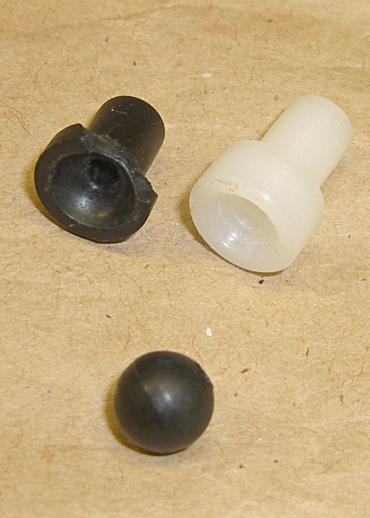
    Broken and new sockets
    Broken and new sockets

    Anyhow, it all worked out OK. The new socket is slightly longer than the old one, as it’s made to fit the derailleur thimble at hand. The end around the socket is slightly thicker, too, as it seemed more meat would add more durability where it was most needed.

    The Rollamajig seems to be discontinued, although some of the smaller online sources still offer it. Building one looks like a straightforward shop project to me.

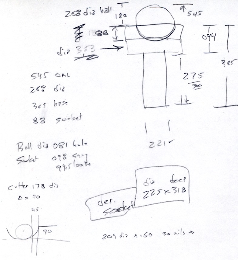
    Ball socket dimensions
    Ball socket dimensions

    The sketch has dimensions in inches, because I was doing this on the lathe. Our daughter measured it in metric and came out with much the same answers, so it’s all good.

  • Aligning to a Hole With a Defocused Laser Spot

    Defocused Laser Spot on Hole
    Defocused Laser Spot on Hole

    When you’re aligning to an edge or scribe mark, you want the laser spot as small as it can possibly be, so you tune for best focus.

    To locate the center of a hole, you first find the edge, then move toward the center by one radius… so you must know the diameter, too. It’s tricky to find an edge exactly on the X or Y axis, which means you generally resort to successive approximation. I did something like that there with good results.

    If you defocus your laser aligner to produce a spot slightly larger than the hole, you can simply position the hole under the beam to produce a nice bright ring. Adjust the focus to make the spot barely larger than the hole and you can get pretty close to the center without any messy arithmetic.

    Now, should you happen to own a real laser aligner, you might actually have a nice-looking defocused spot. My homebrew Orc Engineering aligner, as shown there, starts with the beam from a chip laser in a hacked carpenter’s level, so the defocused spot is rather, mmm, ragged, even after passing through the not-very-restrictive aperture behind the lens.

    With the lens in the spindle, though, I can spin it at a few hundred RPM and persistence of vision blurs the beam into a nice, symmetrical disk. Jog to center the disk around the hole, twiddle the Z-axis position to adjust the focus / size / blobbiness, jog more slowly, tune for best picture, and it’s all good.

    This obviously doesn’t produce jig-boring quality alignment, but, then, I’m not doing that sort of work. In the picture, I’m enlarging a 4-40 hole molded in a Pactec case to fit a 6-32 screw. Normally I’d do that by hand on the drill press, but this time I also had to enlarge the counterbore at the top and figured I’d use a quick G2 with an end mill after I had it aligned for the drill.

    Maybe everybody else knows this trick, but I was delighted to find that it actually works pretty well…

  • Rattle-free Sherline Handwheels

    Knobless Sherline handwheel
    Knobless Sherline handwheel

    The standard Sherline mill comes with tapered plastic knobs on the handwheels, which is exactly what you want for a manual mill and what you don’t want on a CNC machine: they rattle like crazy during computer-controlled moves.

    Some folks contend the knob unbalances the handwheel, but I’m not convinced that’s a real problem. Their advice is to remove the entire knob assembly, leaving a bare shaft sticking out of the motor. Seems a bit extreme to me.

    In any event, shortly after I got the mill, I unscrewed the little retaining screw from the end of each knob, put all the parts in a ziplock bag, tucked it in my tool box, and have been rattle-free ever since.

    The metal shaft is entirely adequate for those rare occasions when I turn the knob manually, the graduated settings let me detect when if I’ve screwed up the acceleration (on a new installation) to the point where the motor is losing steps, and all is right with the world.

    Oh, that orange-barred white tape in front of the motor? That’s a reminder to keep the usual pile of crap away from the spinning knob. That little shaft can fling small objects a fair distance and makes a nasty tangle out of a misplaced red rag…

  • There’s No Undo Key in CNC

    The Axis user interface for EMC2 has a manual command entry mode, wherein you can type G-Code statements and EMC2 will do exactly what you say. That’s handy for positioning to exact coordinates, but I rarely use it for actual machining, as it’s just too easy to mis-type a command and plow a trench through the clamps.

    OK, on a Sherline mini-mill, you’d maybe just snap off a carbide end mill, but you get the general idea.

    I was making a simple front panel from some ancient nubbly coated aluminum sheet. The LCD and power switch rectangles went swimmingly.

    Then I tried to mill an oval for the test prod wires using G42.1 cutter diameter compensation. I did a trial run 1 mm above the surface, figured out how to make it do what I wanted, then punched the cutter through the sheet at the center of the oval and entered (what I thought were) the same commands by picking them from the history list.

    EMC2 now handles concave corners by automagically inserting fillets, so it must run one command behind your typing. I drove the cutter to the upper-right end of the oval (no motion) so it could engage cutter comp mode, entered the G2 right endcap arc to the lower edge (cuts straight to upper right), and then did something wrong with the next command.

    Epoxy-patched front panel hole
    Epoxy-patched front panel hole

    The cutter carved the endcap properly, then neatly pirouetted around the end and started chewing out an arc in the other direction. Even looking at the command trace I can’t figure out what I mistyped, but as it turns out it doesn’t matter… I was using the wrong dimensions for the hole anyway.

    So it’s now patched with epoxy backed up by a small square of aluminum. When it’s done curing, I’ll manually drill a pair of holes at the right coordinates, manually file out the oval, shoot a couple of coats of paint, and it’ll be OK.

    Nobody will ever know!

    If I recall correctly, Joe Martin of Sherline was the first person to observe that, unlike word processing programs, CNC machines lack an Undo key…

    Update: Like this…

    Patched panel - rear view
    Patched panel – rear view

    The shoot-a-couple-of-coats thing did not go well: a maple seed landed on the front panel. Ah, well, it’s close enough. Here’s a trial fit; the bellyband height extenders on the sides need a dab of epoxy and a shot of paint, too, but I may never get a round ‘tuit for that.

    Front panel trial fit
    Front panel trial fit

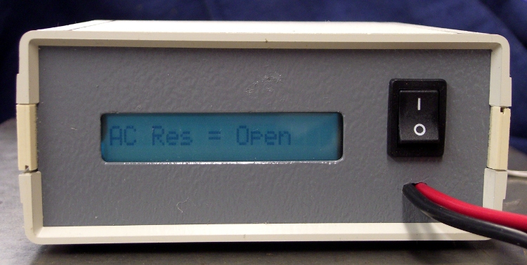
    It’s the long-awaited Equivalent Series Resistance meter…

  • Sherline Collet Pusher Tweakage

    Better-fitting pin & redrilled hole
    Better-fitting pin & redrilled hole

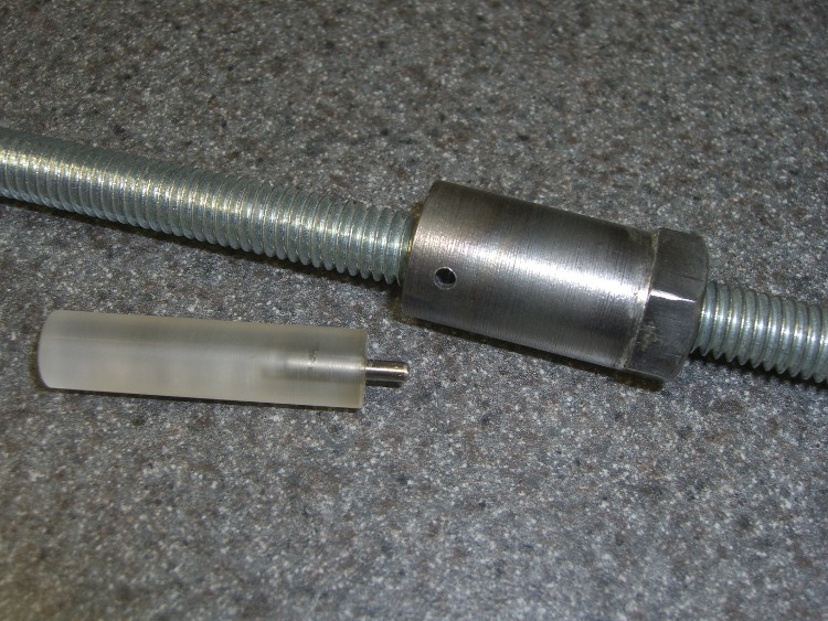
    My simple collet pusher has been working OK, but the locking pin was a few mils too small for the hole in the spindle and eventually put a burr on the edge. The fix is straightforward, although I’ve been putting it off for far too long; I warned you about this in the original post.

    Shoemaker’s child, anyone?

    The locking hole in the spindle starts life at 0.094 inch. I grabbed a #40 drill in a pin vise and drilled it out to 0.098 by hand, which wasn’t nearly as difficult as you’d think, took out all the deformed metal, and didn’t even leave any burrs. Ditto for the hole in the collet pusher.

    My heap yielded a defunct #40 drill, from which I cut 15 mm of shank with a Dremel abrasive wheel. Chucked the shank stub in the drill press, spun it up, and applied a Dremel grindstone to put a very short taper and a nice smooth end on it.

    Pulled the old pin from the handle I built a while ago, added a dot of urethane glue to the new pin, and squished them together (tapered end out!) in a vise until cured. Done!

    No, that’s not a burr on the hole in the pusher…

  • Remote Control Button Shield

    Button shield in place
    Button shield in place

    Mary was giving one of her vegetable gardening presentations and had the projector go into Mute mode all by itself. It’s hard to debug something like that under pressure, but (as nearly as we can tell) the projector’s remote control (!) got squashed inside the tote bag and managed to tell the projector to go mute itself…

    The remote control has buttons that stand proud of the surface by about 2 mm and, worse, they’re exposed from all sides. There seems to be no way to turn the mumble thing off, other than by removing the batteries, so I conjured up a quick-and-dirty button shield. Not the fanciest thing I’ve ever made, but it’s sufficient for the purpose.

    [Update: Apologies to all you Arduino fans who think this should have something to do with a remote-control circuit board plugged atop a Diecimila, but I think the Arduino designers could have picked a more descriptive term than “shield”. Plenty of folks seem to arrive here by searching for the obvious keywords and go away unhappy. If you’re looking for Arduino stuff, click on the obvious tag in the right-side column that’ll call up everything I’ve written about on the subject… ]

    Sizing the perimeter
    Sizing the perimeter

    I thought about making a tidy form-fitting slab that would fill the entire space between the button matrix and the case, but that gets into curved edges and fussy fitting; fortunately, I came to my senses. Without wanting to make a prototype to get the second one right, I simply trimmed the outside of the polycarbonate slab to a ruthlessly rectangular 33×50 mm. That gives about 2 mm clearance on each side of the button matrix and fits with about 1 mm clearance from the case. The lengthwise dimension is what it is.

    The 29×46 mm pocket must be about 3 mm deep to clear the button tops.

    The G-Code came from the Hugomatic pocketRect2points generator, which worked just fine; normally I hammer out my own G-Code, but I was leaving on a trip the next day. The cut depth of 1 mm per pass was probably too conservative. A cutting speed of 300 mm/min with a 2000 rpm spindle worked reasonably well with water cooling.

    Pocket milling with water coolant
    Pocket milling with water coolant

    A 1/8″ end mill produced corner radii that matched the buttons fairly well, which means it took a loooong time to chew out the pocket. The picture shows the mill knee-deep in a pool of water and swarf; I vacuumed the chips out at the end of each pass and added more water.

    Double-stick tape held the polycarb & sacrificial plate to the tooling plate, which worked surprisingly well given that I just wiped the grunge off and squashed it down. A machinist’s square aligned the rectangle closely enough and, of course, I used the laser aligner to set the coordinate zero to the left-front corner.

    For lack of anything smarter, a rubber band holds the shield in place on the remote. I thought about fancy hinges and Velcro and stuff like that, but the projector is used by non-technical folks and, as nearly as I can tell, the remote control never gets used at all.

    Quick and dirty, indeed: about two hours, first doodle to snapping the rubber band, including a bit of time wasted on an ancient G-Code generator that spat out bad coordinates.

    Plus time to write this up, natch…