The Smell of Molten Projects in the Morning

Ed Nisley's Blog: Shop notes, electronics, firmware, machinery, 3D printing, laser cuttery, and curiosities. Contents: 100% human thinking, 0% AI slop.

Tag: Sherline

Sherline CNC mill

  • Toner Transfer PCBs: Alignment Accuracy

    Here’s an example of the dimensional accuracy you can get from toner-transfer PCBs in real life.

    I drill the holes with a CNC-ed Sherline mill, so they’re pretty much spot on. Drilling the holes by hand simply isn’t practical: there’s no way to get both global alignment and local accuracy.

    The toner transfer sheet, printed on a laser printer, gets aligned to the existing holes atop a light table. The paper stretches & shrinks and moves around while printing, but I can generally average out the errors so that the 24-mil holes (the smallest I generally use) across the board have no more than a few mils of error: the pads don’t show more than that inside the drilled holes. In the picture below, you can see a dark rim around the corner alignment hole that looks worse than it really is due to the perspective.

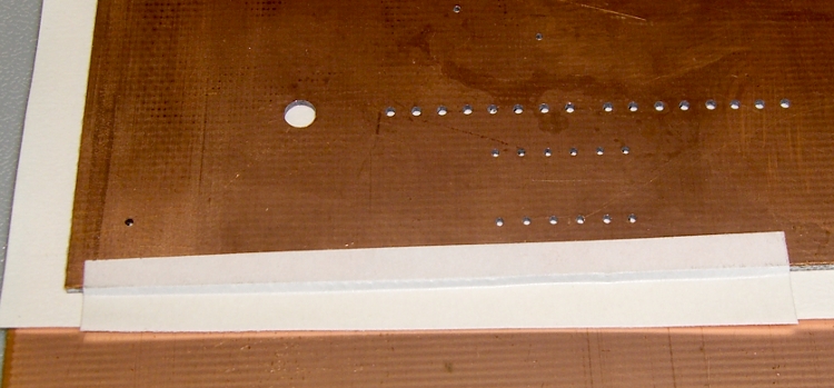
    I put the toner transfer sheet on the light table, toner-side up, lay the PCB atop the paper, and adjust for best overall alignment. I then tape them together along one edge with strips of laser-printer address labels: guaranteed to hold up to high temperatures, which is more than you can say for most tapes.

    PCB alignment and taping
    PCB alignment and taping

    Here’s the board after etching both sides, with the black toner and green sealant film still in place. The toner & film are slightly smeared from the solvent I used to clean off the other side before etching it. The brownish dabs on the green areas come from a brown Sharpie that works fine as a touch-up etching resist.

    WWVB Simulator - Top surface toner mask
    WWVB Simulator – Top surface toner mask

    The narrowest traces are 16 mils, most of the others are 32 mils, and the fat ones down the middle of the chip are 40 mils. Click on the images for bigger versions; you’ll get some JPG compression artifacts, but the resolution is good enough to see what’s going on.

    Here’s the same area with the toner removed and a touch of silver plating applied to make it pretty and more easily solderable. The colors aren’t particularly reliable; in real life, it’s a lot more silvery.

    Top surface copper
    Top surface copper

    Fairly obviously, the alignment isn’t nearly as good as you’d expect from the initial taping. In round numbers, the pads to the left side seem offset by about the diameter of the holes; call it 25 mils. The holes in the DIP pads are off by perhaps 10 mils.

    The bottom surface looks pretty much the same, with similar alignment issues.

    Bottom surface copper
    Bottom surface copper

    The misalignments are not uniform, as you’d expect if the toner transfer sheet moved across the board during fusing. The sheet deforms during the fusing process in a completely unpredictable way, despite my trying all of the usual tricks:

    • Pre-shrinking the transfer paper by running it through the printer with a pure-white image (so no toner gets applied)
    • Fusing quickly after printing to prevent moisture absorption (there’s a limit to how fast I can work)
    • Taping more than one edge to lock the paper in place

    It’s fair to say you (well, I) can get within 25 mils of a board hole for sure, less than that most of the time, and be spot on over much of the board. I use large pads and vias for anything I have control over, as witness the pads surrounding the DIP, and avoid very fine features near holes.

    Anyhow, it’s good enough for what I do, but you shouldn’t get your hopes up that toner-transfer circuit boards come anywhere close to commercial quality. If you’re doing a lot of pure surface-mount work, it’ll probably be good enough because there’s no need for global alignment to holes in the underlying board. Obviously, the smaller the board, the better off you’ll be.

    I etched this board by rubbing ferric chloride on it with a sponge (wearing forearm-length rubber gloves and a shop apron!), renewing the solution as it turned black and gooey. Works like a charm, gives good control of the process, doesn’t erode the Sharpie masking, doesn’t over-etch the traces (much, anyway), and uses less etchant than soaking the board in a bath.

    I have other posts describing the process in more detail. Search for PCB, toner-transfer, and other keywords to unearth those entries.

  • Sherline Z-axis Backlash: Check the Bearing Preload Nut!

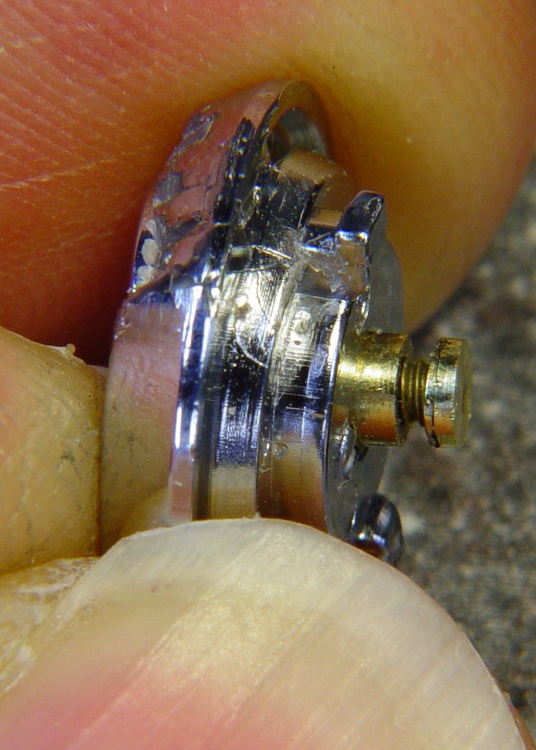
    Loose bearing nut
    Loose bearing nut

    I don’t do any fancy 3D milling, so it takes a lot of Z-axis backlash to get my attention. While setting up for some circuit-board drilling, I finally noticed that the backlash far exceeded even my slovenly specs: something like 20 mils.

    The Z-axis backlash adjusting nut on the saddle was as snug as it usually is. Heaving on the saddle, though, pulled it up & down and moved the handwheel on the top of the Z-axis motor.

    Ah-ha! That says the leadscrew itself is moving, which shouldn’t be possible because it’s captured at the bearings in the stepper motor mount.

    Some tedious disassembly later, the top picture shows the Z-axis leadscrew and motor mount, with the nut obviously too far away from the lower ball bearing housing. The nut was finger-loose and I moved it while extracting the leadscrew; it’s supposed to be snug against the bearing in normal operation.

    The solution is a drop of Loctite, which should be applied to the canonical “clean and dry” threads. Hosing this part of the leadscrew down with solvents isn’t a good idea, because you don’t want any inside the lower bearing in the motor mount, so I spent some Quality Shop Time spinning the threads against a (dry) rag, running the nut to the other end (all of a few millimeters), and repeating until most of the oil was gone.

    Properly adjusted nut
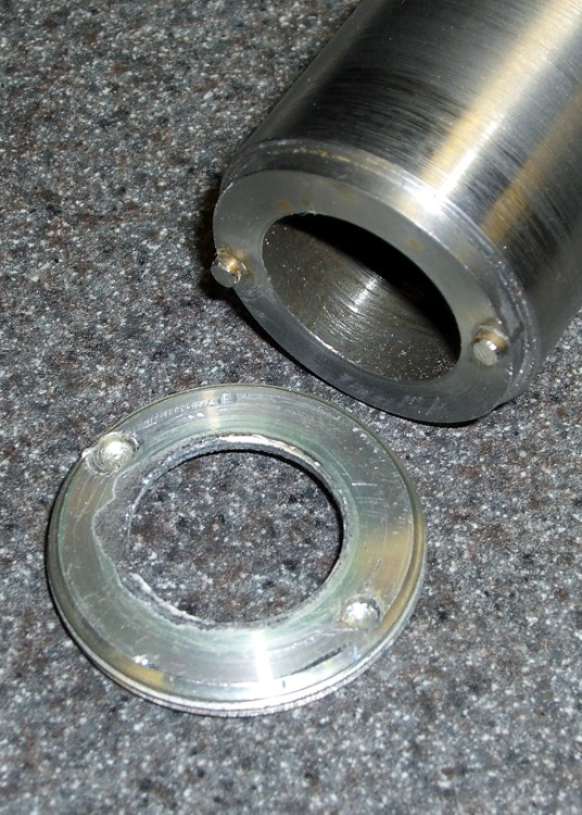
    Properly adjusted nut

    Sherline documents how to assemble & install the motor mounts, so there’s not much mystery involved. I loosened the preload nut until the housing spun freely on the shaft, then tightened it a teensy bit; the housing still spun freely and there’s no detectable end play.

    Reinstallation requires putting the motor mount at the same spot on the Z-axis column as before. I moved the saddle to the top of the column, ran the leadscrew into the saddle nut, and then tightened the motor mount screws. That allows the mount to move to suit the saddle nut’s position, rather than going through the tedious saddle alignment process I mentioned as part of the gib adjustment.

    It’s all good… call it 3 mils of backlash on all three axes.

    Memo to Self: It’s possible to run the Z-axis backlash adjusting nut off the top of the leadscrew thread, then re-engage it without removing the motor mount. The trick is to hold the anti-backlash nut firmly against the saddle nut while turning the leadscrew to engage the thread. Remember that it’s a left-hand thread…

  • Sony DSC-H1 Shutter Button Repair: Putting It Together

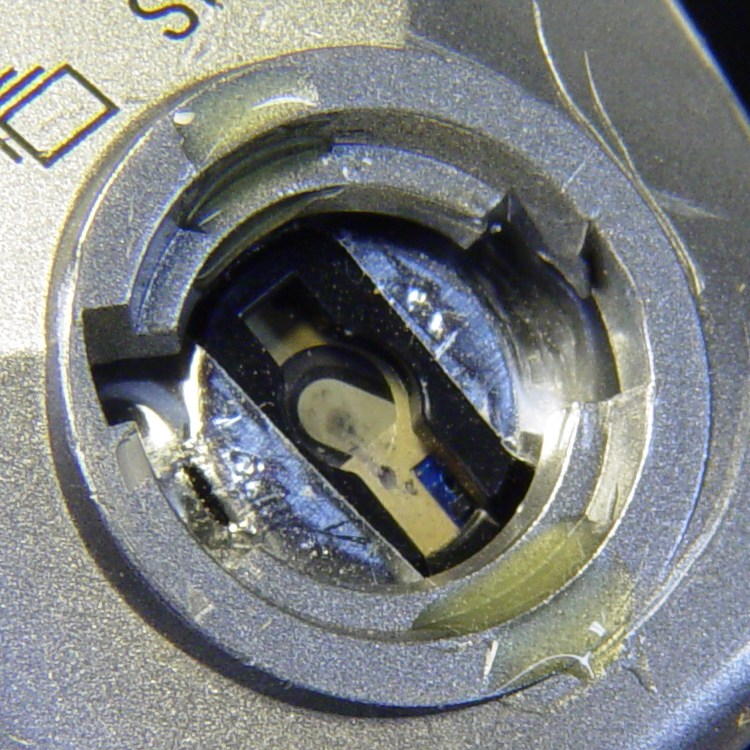
    The story so far: Damage Assessment and Button Milling.

    Some key distances:

    • Bezel bottom 3.3 mm thick, excluding depression on bottom surface
    • Screw head sticks out of depression 0.9 mm

    Some deft work on the bezel installed in the camera, using the blunt end of a transfer punch, a pin vise, and a calculator reveals these protrusions:

    • 1.4 mm does not trigger anything
    • 2.1 mm triggers the half-pushed focus action
    • 2.4 mm reliably triggers the shutter

    So the new stem can stick out about 1.4 mm when the button is released and must not stick out more than 2.4 mm with the button fully depressed: a whopping 1 mm of travel!

    Eyeballing the shutter release on my DSC-H5, that seems to be about right. I think it has more travel between “released” and “half pressed” than those measurements indicate, but it’s close. And sloppy, too: the H5’s button has a lot of side-to-side wobble, indicating that the stem is not a close fit in the bezel hole.

    The screw head is 3 mm dia after being turned down and that’s about the right size for the nut that will adjust the travel distance, as it must fit into the recess in the bezel. The nut sets the protrusion when the shutter button is released: 1.4 mm.

    The distance from the shutter button’s bottom to the bezel sets the travel from “released” to “click”: 1 mm, more or less. They’re held apart by the spring, so that’s the default state.

    Circular Milling the Nut
    Circular Milling the Nut

    I re-centered the 3-jaw chuck under the spindle, put a 1-72 nut on the turned-down screw, and applied some gentle manual CNC to convert the nut from a hex to a disk. The trick is to approach the nut from the right side (the +X side) and go clockwise around it (climb milling), so that the cutting force tends to jam the nut against the screw head. Do it the other way and the nut will zip downward away from the cutter

    Surprisingly, I got that right the first time.

    Using a 2 mm end mill and figuring a 2.9 mm final diameter, the radius of the circle to move the end mill around the nut is:
    R = (2.9 + 2.0) / 2
    So the G-code for one pass looks like:

    #<R>=[[2.9+2.0]/2]
    G1 X#<R> F150
    G2 I[0-#<R>]
    
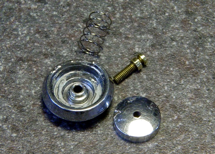
    Shutter Button Parts
    Shutter Button Parts

    Now, given the fragility of that setup, you don’t cut it all at once. You start from a diameter of maybe 4 mm and go down by 0.2 mm until you hit 3.0, then make a final pass at 2.9 mm. EMC2’s AXIS MDI mode makes this easy enough: type in the commands for a pass at 4.0 mm, then click on the previous command, change 4.0 to 3.8, and then just clickety-click.

    Spindle far too slow at 3000 RPM, feed at 150 mm/min seemed fine. Sissy cuts worked out OK.

    After the first few passes, my dim consciousness became aware of the fact that this is how I should have turned down the screw head…

    Button Assembly - Top
    Button Assembly – Top

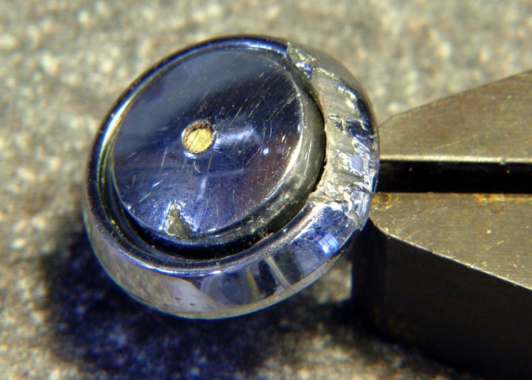
    I cleaned up the bezel by putting it in an ultrasonic cleaner to shake the crud off, put it on a warm firewall router overnight to dry it out, then slobbered some Plastruct solvent adhesive into the cracks and clamped it for another night. The bezel was slightly out-of-round from the damage, so I hand-trimmed the bent plastic using a “high speed cutter” (#193, basically an end mill) in a Dremel flexible shaft at about 1/3 max speed until the shutter button bottomed out smoothly within the inner recess. Not a bit of CNC to be seen: hand held all the way.

    Button Assembly - Bottom
    Button Assembly – Bottom

    Then loosen the nut a bit, poke the screw through the bezel, put the spring on, and screw the shutter button in place. Adjust the nut so the screw head is 1.4 – 1.5 mm from the bottom of the bezel with the nut resting in the recess.

    Button Assembly - Pressed
    Button Assembly – Pressed

    Twiddle the shutter button until the screw head protrudes 2.4 mm from the bezel with the button pressed down.

    That’s measured with the hole-depth tang of a caliper, sitting atop the screw head. I don’t believe there’s 0.1 mm accuracy in the measurements, but they’re close enough. I did file off a few mold flash bumps from the shutter button & bezel during this adventure.

    Mark the screw threads above the button, unscrew it, chop the screw off with a stout diagonal cutter (it’s brass and not very thick, it’s OK), file the end flat, clean up the threads.

    The trick seems to be that the button must rest just below the inner ring of the bezel, so that it bottoms out smoothly when pressed. If it’s above the ring, then one side will hang up. The ring depth thus seems to limit the maximum travel, although I can’t say whether this is the way it’s supposed to work or not.

    I iterated & filed until the screw was flush with the top of the button with it screwed down to the proper position. It helped to figure out that one turn of the shutter button on the screw changed the “pressed” protrusion by 1/72″ = 0.35 mm.

    Urge some low-strength Loctite under the nut and into the shutter button’s hole, reassemble everything, and you’re done.

    Urethane Adhesive on Body Socket
    Urethane Adhesive on Body Socket

    The fall bent the bezel tabs so they no longer latch firmly in the camera body. I put two dabs of urethane adhesive on the socket in the body. The adhesive expands (foams!) as it cures; I hope it will lock the bezel in place while still allowing it to be removed if needed.

    I dabbed off most of the adhesive you see in the picture before installing the bezel; it’s not as awful as it looks!

    The final result has slightly less travel than the (undamaged, original) shutter button in my DSC-H5, but it works perfectly: half-press to focus, full press to trigger the shutter.

    Repaired Shutter Button
    Repaired Shutter Button
  • Sony DSC-H1 Shutter Button Repair: Rebuilding the Button

    Having figured out what to do, I started with the button, which is chromed plastic, nothing too fancy, and not at all hard to machine.

    Laser Aligning to the Button Stem
    Laser Aligning to the Button Stem

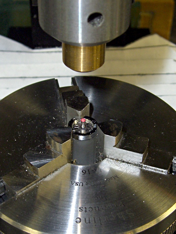
    A small post turned from an acrylic rod (the gray cylinder) supports the button in the Sherline 3-jaw chuck attached to the mill table; that was the only way to keep it reasonably level. Laser alignment got eyeballometrically close to the middle; it looks a bit off to the right, but the end result was OK.

    Removing the Broken Stem
    Removing the Broken Stem

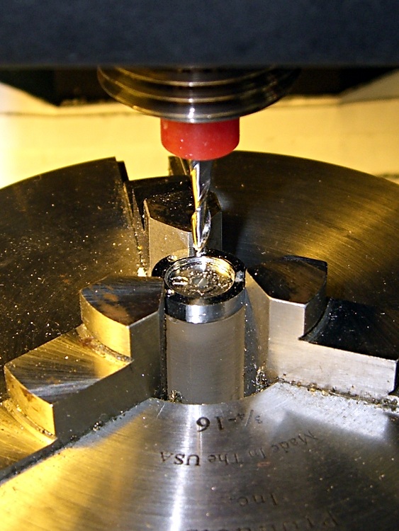
    A 2 mm end-cutting bit chewed off the stem in short order; I set the jog speed to about 100 mm/min and just jogged down until the cutter was flush with the button. Spindle at 4000 rpm, for lack of anything smarter.

    I decided to go with a 1-72 brass machine screw, which is slightly larger (1.75 mm) than the original 1.5 mm button stem. That means I must drill out the bezel hole, as well, but the 1.5 mm diameter of the next-smaller 0-80 screws in my assortment was a sloppy fit.

    A touch of manual CNC for the drilling, #53 with the spindle at 3000 rpm, Z touched off at the button’s surface:

    G81 Z-4 R3 F150

    The spindle was slow enough and the feed fast enough to keep from melting the button without applying any coolant.

    I tapped the hole 1-72 by simply screwing the tap in with my fingers…

    Chuck-in-chuck For Head Shaping
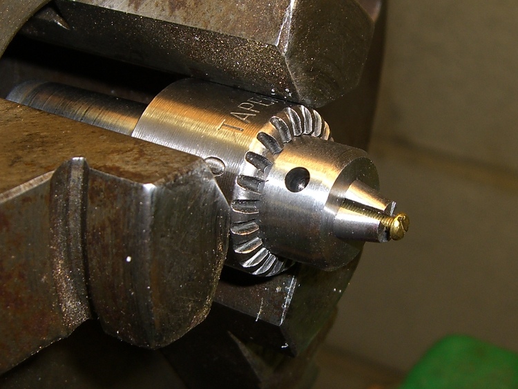
    Chuck-in-chuck For Head Shaping

    The 3-jaw lathe chuck doesn’t grip a 1-72 screw (no surprise there), so I grabbed the screw in the Sherline’s smallest drill chuck and poked that in the lathe. This doesn’t make for great concentricity, but it was close enough. The right way, as my buddy Eks reminds me, is to slit a nested bunch of brass tubing and use them as collets, but … next time, fer shure.

    Button With Reshaped Screw Head
    Button With Reshaped Screw Head

    Anyhow, here’s what the button & screw look like so far. The backside of the screw head looks like it needs some cleanup; there’s nothing like taking a picture to reveal that sort of thing.

    The pencil lead is 0.5 mm and the grid in the background has 1 mm squares, just to give you an idea of the scale.

  • Slitting Copper Sheet

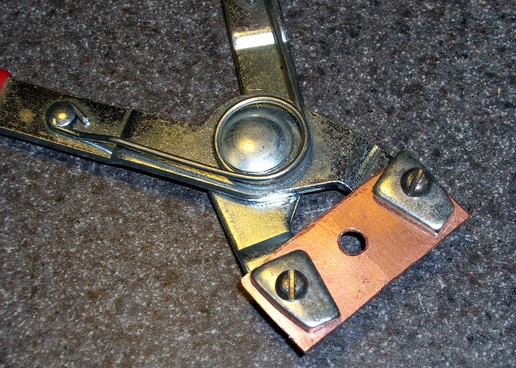
    Slitting Copper Jaws
    Slitting Copper Jaws

    I’m kludging up a clamp to grab AA cells around their positive terminal so that I can resistance-weld nickel strips to that button. The general idea is that the current passes through the strip, through the button, and out the side to the clamp, rather than trying to heat the button through the strip from the top.

    Trial Fitting the Jaws
    Trial Fitting the Jaws

    A snap-ring pliers has pretty nearly all the right attributes, so I’m making up a set of copper jaws with a hole in the middle to grab the terminal. Basically, I whacked off a ring from a copper pipe, hacksawed it lengthwise, hammered it flat (work-hardening it in the process), and drilled some holes.

    Then I grabbed it in the Sherline vise and set up a teeny 4-mil slitting saw. A bit of manual CNC ran the saw past the copper and, after a while, the top half just fell over dead with a perfectly shiny cut right down the middle!

    Slitting Success
    Slitting Success

    Useful things to remember for the next time around:

    • Cut only 0.2 mm into the copper per pass
    • 100 mm/min feed is fine
    • 4000 rpm is fast enough
    • A drop of cutting lube is a bunch on this scale

    This worked out a whole lot better than I expected…

  • Keeping the Screws in Sherline Hold-Down Clamps

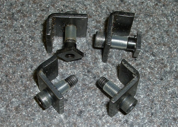
    A small improvement: add a snippet of heat stink shrink tubing to the screw in the L-shaped hold-down clamps and the screw won’t go walkabout in your tooling widget case.

    Make it the same length as the distance from the clamp to the surface and it’ll remind you how far to screw on the T-nut when you swap the clamps from tooling plate to milling machine table.

    The Sherline Mill Vise (PN 3551) comes with a set of clamps. They’re also available separately as the 4-Jaw Hold-Down Set (PN 3058).

  • Recumbent Bicycle Amateur Radio Antenna Mount

    Homebrew antenna mount
    Homebrew antenna mount
    Finished mount top view
    Finished mount top view

    Having had both of our commercial antenna mounts fail, I decided to make something that could survive a direct hit. It turns out that the new mounts are utterly rigid, which means the next failure point will be either the antenna mast or its base structure. We’ve occasionally dropped the bikes and when the antenna hits something on the way down, the mount is not the thing that bends…

    Incidentally, the Nashbar 5-LED blinky white light aimed rearward seems to push motorists over another few feet to the left. Nobody quite knows what we are from a distance, but they do notice that something is up ahead. That’s just about as good as it gets; we tend to not ride in the wee hours of the morning when bike lights just give drunks an aiming point.

    Rough-cut stock
    Rough-cut stock

    The overall structure is a 2-inch square aluminum extrusion, with a hole in the top that matches the right-angle SO-239 base connector salvaged from the Diamond mount and a 1/2″ nylon stiffener plate in the middle. A pair of relentlessly square circumferential clamps attach it firmly to the top seatback rail. A coaxial cable pigtail ensures that the antenna base makes good electrical contact with the seat. I’m not convinced the bike makes a good counterpoise, so we’re now using dual-band antennas that are half-wave on VHF.

    Stainless-steel hardware holds everything together, as I’m sick and tired of rust.

    Drilling box beam
    Drilling box beam

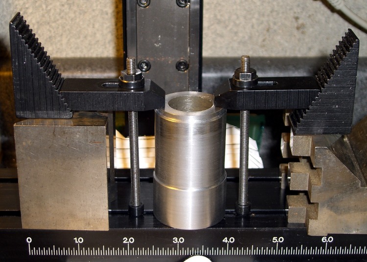
    Not having a huge drill, I helix-milled the SO-239 hole, then reached down through the box to drill the hole for the plastic block retainer screw. Flip the box in the vise, drill four holes for the clamps (I love manual CNC for that sort of thing), manually deburr the holes, and it’s done.

    The block of plastic is a tight slip fit inside the box extrusion, with slightly rounded corners to suit. I milled the slot across the top to a slip fit around the SO-239 connector.

    The two clamps were the most intricate part of the project and got the most benefit from CNC.

    Helix-milling the seat-bar clamp
    Helix-milling the seat-bar clamp

    The clamp hole must have exactly the same diameter as the seat top tube. I helix-milled the hole to an ordinary 5/8″; I have trouble drilling holes that large precisely in the right spot with the proper final diameter. Milling takes longer, but the results are much better.

    Helix-mill the other block while you have the position set up, then flip and reclamp to drill the pair of holes that match the box extrusion. Drill 10-32 clearance (#9) all the way through.

    Flycutting Clamp Slit
    Flycutting the Clamp Slit

    Bandsaw the blocks in half, paying some attention to getting the cut exactly along the midline, then flycut the cut edge to make it nice & shiny & even. That should result in 1 or 2 mm of slit between the blocks when they’re clamped around the seat rail.

    Finished seat-bar clamps
    Finished seat-bar clamps

    Break those relentlessly sharp edges & corners with a file.

    I finagled the dimensions so a 1-1/2″ socket-head cap screw would have just enough reach to fill a nut, with washers under the screw and nut. Your mileage may vary; I’ve gotten reasonably good at cutting screws to length.

    Normally, you tap one side of each clamp for the screws, but in this situation I didn’t see much point in doing that: the box must attach firmly to the clamps and I was going to need some nuts in there anyway.

    Finished parts
    Finished parts

    With all those parts in hand, assembly is straightforward. Secure the SO-239 with its own thin nut, screw the plastic block in place, hold the clamps around the seat bar, poke the cap screws through, dab some Loctite on the threads, install nuts, and tighten everything. That all goes much easier with four hands!

    The grounding braid fits into a huge solderless connector that must have been made with this application in mind. It originally fit a 1/2″ lug, but with enough meat that I could gingerly file it out to 5/8″ to fit the SO-239 inside the aluminum extrusion. I’ve had those connectors for years without knowing what they were for!

    I eventually came up with a simpler and even more ruthlessly rugged mount that’ll appear in my column in the Autumn 2009 Digital Machinist. More on that later… [Update: There]