Ed Nisley's Blog: Shop notes, electronics, firmware, machinery, 3D printing, laser cuttery, and curiosities. Contents: 100% human thinking, 0% AI slop.
Real men have real CNC milling machines and real CNC milling machines have home switches. I have an itsy Sherline CNC mill, but now my mill has home switches just like a Real Man’s mill.
Sorta, kinda.
Truth is, I really don’t need home switches for the Sherline. I haven’t done any “production” milling with fancy fixtures, so zeroing the coordinate system to the lower-left vertex of the part-to-be-milled works reasonably well. But I figured it’d be fun to see what I was missing…
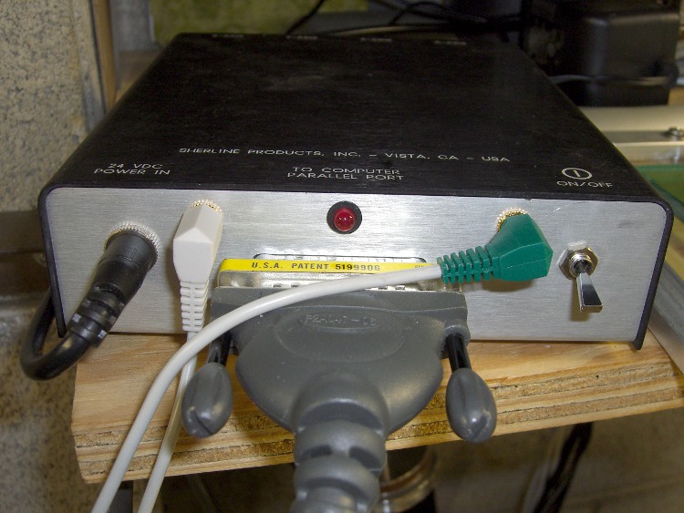
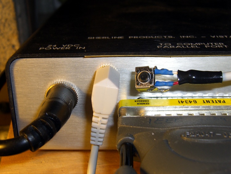
The first step was to hack another jack on the Sherline controller box and connect it to parallel port bit 10. The process is pretty much the same as I used for the probe switch jack documented there. I actually put the jack in the hole used for the power LED and drilled a new hole for the LED smack in the middle above the connector.
Sherline Controller with Probe and Home Jacks
The simplest way to do home switches is to wire them all in parallel using a single port pin. You can even wire the probe switch in parallel with home switches, too, but I figured it’d be nice to have separate jacks… and, besides, the controller still has a few port pins left.
Adding the home switches requires a few lines (adapted from there) in custom.hal that connect the sense inputs in parallel:
net homeswitches <= parport.0.pin-10-in-not
net homeswitches => axis.0.home-sw-in
net homeswitches => axis.1.home-sw-in
net homeswitches => axis.2.home-sw-in
Using the -not suffix flips the sense of the input so the signal is True when the buttons get pushed. I don’t know of any algorithmic way to determine the actual logic states for a given button configuration, so just try it, use Halmeter to see what happens, then flip as needed.
The catch with adding home (or limit) switches is that Sherline mills have an attentuated mechanical structure with no good places to affix switches. I figured a trio of microswitches and a few dollops of JB Quik epoxy would suffice; if I must remove the switches, a quick shot with a chisel should pop the epoxy right off the metal.
The microswitches have about 20 mils of overtravel. I located the switches so the actuator buttons are bottomed out against the cases with the axes at the far limits of their travels. The steppers are puny enough to stall when the mechanical bits hit their hard limits, so there’s no risk of wrecking the machinery or knocking the switches off.
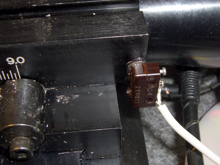
The X-axis home switch goes on the right side of the table, where it contacts the Y-axis slide at the end of travel. Putting it there also means I can remove the table by simply running the leadscrew out of the nut and pulling the whole affair off to the right. I lashed the switch cable to the motor cable with (wait for it) cable ties, which is probably a Bad Idea for larger machines, but seems to be OK in this situation.
X Axis Home Switch
The Y-axis home switch goes at the rear of the machine base, aligned with the plastic bushing I put there to capture the end of the leadscrew. That’s the travel limit for the bare table, but the Sherline tooling plate sticks out another half-inch: the plate hits the column before the table hits the bushing. Alas, I use the plate a lot.
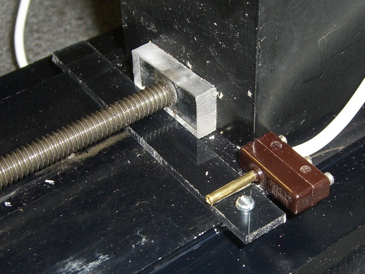
Rather than futz with an adjustable switch position, I made a removable extender. The 3 mm (1/8″ nominal) thick plastic strip has 1 mm milled off the bottom, leaving a tab on the left side that snaps over the dovetail. The screw extends down past the dovetail on the right, so the whole affair slides back & forth just enough to connect the Y-axis slide with the button. The brass tubing exactly fits the tit on the switch actuator and is urethane-glued to the strip.
It’s removable by lifting the left end and sliding the whole affair out under the leadscrew.
Y Axis Home Switch with Extender
The alternative, putting the Y-axis home switch on the very front of the base, would expose the switch & cable to all the slings & arrows of outrageous fortune to be found around the area of the countertop I use most. That may still prove to be a better location: if the back doesn’t work out, it’s easy to move.
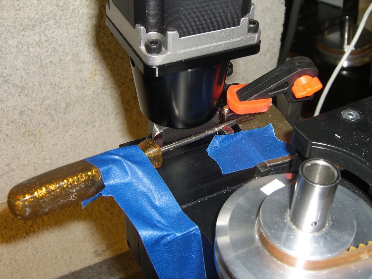
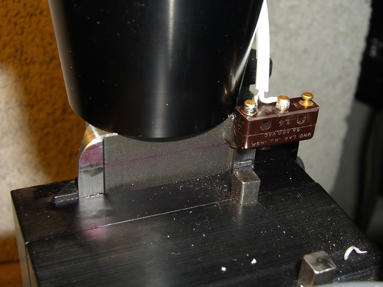
The Z-axis switch had to go at the top-of-column mechanical limit, as homing to the downward limit of travel seemed fraught with peril. I epoxied the switch in place by clamping it to a shim atop the Z-axis slide to align the switch body, then applying gentle sideways pressure with a small screwdriver.
Epoxying the Z Axis Switch
This is what it looks like after the epoxy cured. The square key bar sticking out of the extender block clears the switch with plenty of room to spare, no matter what it looks like.
Z Axis Home Switch
The cables from all three switches go to a common junction where they’re connected in parallel to the cable leading to the green plug in the top picture.
Tomorrow, the configuration file that makes all this work…
My buddy Eks once observed that knurling is something you want to do on somebody else’s lathe, because it puts so much stress on the bearings. As it happens, both Home Shop Machinist and Machinist’s Workshop have run several articles / series on improved knurling, ranging from better clamp knurling tools to a wonderful widget that turns your lathe into something like a shaper with a rotary axis.
I wondered if a touch of G-Code could do the same thing on my Sherline CNC milling machine, using an ordinary end mill…
Pretty much, yes, it can.
The knurled diamonds aren’t raised above the surface, as they are in classical crush-rolled knurling, but my fingers can’t really tell the difference. That’s a chunk of 1-inch PVC pipe, turned smooth in the lathe and knurled with a 2-mm end mill; the fluff is left over from wiping off the swarf with a rag.
The setup mounts the workpiece in the rotary table on the right with the tailstock on the right end. In this case, a little boring (on the lathe) produced a slip fit on the tailstock ram, but you probably should have a plug that supports the tubing with a center-drilled hole for the tailstock’s dead center.
CNC Knurling SetupGeometry Sketch
The general idea is to do the cutting at a 45-degree angle in front of the workpiece, where the end mill will carve a neat 90-degree recess almost like a real 90-degree conical engraving point. This sketch shows the layout, albeit for a very large cutter and a very small workpiece. The YZ origin is at the center of the workpiece, with the X origin at the left edge of the knurled region.
The Z axis remains constant at the level where the bottom of the cutter intersects the 45-degree angle at the proper depth-of-cut. Then you drive Y into the workpiece and drag the end mill along X while twirling A to make a single cut. Move Y out to clear, return X to the start, index A by the angle between the knurls, repeat.
This isn’t perfect, because the bottom of the cutter isn’t parallel to the cut between the knurl diamonds. The leading edge cuts too high / low and the trailing edge cuts too low / high (depending on which way you’re moving X and twirling A), but for small cutters and large workpieces the approximation is probably Close Enough.
Machined Knurl Measurements
The key number is the diametral pitch DP: the number of knurl diamonds around the workpiece divided by the workpiece OD in inches. Machinery’s Handbook suggests that a DP of 48 is coarse and 96 is fine. Measuring some knurled tools lying around the shop shows those values aren’t hard numbers, but they’re a start.
Given an initial DP and the workpiece diameter, figure an actual DP that will produce an integral number of knurl diamonds around the circumference (call it NA):
NA = round (DP * OD) to the nearest integer
Actual DP = NA / OD
Knowing the number of diamonds NA, figure the width of a diamond in degrees (call it the Width-in-Angle):
WA = 360/NA
and also as a fraction of the circumference in inches:
W = π * diameter / NA
Typical knurl diamonds seem to be about twice as long their width, so the nominal aspect ratio is 2. Given the desired length-of-the-knurled-region, figure an actual aspect that will produce an integral number of diamonds along the length (call it NX):
NX = round (length-of-knurl / nominal-aspect) to the nearest integer
Knowing NX, figure the angle to turn (call it TA) while making the cut along X:
TA = WA * NX
Depth of Cut Sketch
This sketch shows the depth-of-cut geometry, with the cutter producing skeletal points where the cut just touches the next knurl over. With a 45 degree angle between the diagonal, all the trig boils down to factors of √2.
The perimeter of an NA-sided polygon inscribed in a circle of radius R (which is just the OD/2 is:
Perimeter = 2 NA R sin (180 / NA)
which simplifies to
Perimeter = NA OD sin (180 / NA)
The length of the chord L from tip to tip for such a polygon:
L = Perimeter / NA
The side of the triangle from the corner of the cut perpendicular to the chord is half the chord length, because it’s an isosceles triangle with angles of 45 and 90 degrees.
The height of the segment above the chord:
(L / 4) tan (WA / 4)
The total depth-of-cut along the diagonal is the sum of those two numbers. Given that, figure the coordinates (Y is negative because it’s out in front):
Z = (radius – depth) / √2
Y = -Z
Now, because the end mill has a nontrivial length along the X axis, it’s doing too much cutting. Reductio ad absurdum, imagine putting a 1-inch knurl along a pencil using a 6-inch end mill: the thing would cut a horizontal swath the entire length of the knurled region, leaving no material behind.
So it makes sense to heave in a Fudge Factor limiting the actual depth-of-cut to some percentage of that value. The knurl above was with that factor set to 0.50, but (as with rolled knurls) be sure to test in an inconspicuous spot before actual use. Subtract the shrunken depth-of-cut from the radius as above to get the YZ coordinates.
Notice the difference between the ends of the cut in that first picture: you can clearly see the shape of the end mill’s cylindrical cut. I ran the cutter at 2500 rpm to avoid overheating the PVC, so you can see the cuts on the top edges of the diamonds: the trailing edge makes neat little swipes. In actual practice, you’d run it much faster to get a smooth cut.
Then it’s just a matter of writing some G-Code…
Knurled Pencil
Herewith, the G-Code that did the pencil, with depth-of-cut set to 0.30. It cuts to the right and cuts to the left, then indexes to the next cut by unwinding the A axis. The nominal DP = 48 makes for a coarse, yet oddly attractive, knurl. The variable names don’t track what you see above, but should be pretty obvious. Also see the notes on optimizations down near the bottom.
(Engraved knurling)
(Ed Nisley - KE4ZNU - May 2010)
(G55 Coordinate Origin: 	X to left of checkering)
(							YZ on centerline of workpiece)
(							A = 0 wherever you like)
(Touch off tool center at Y = workpiece radius)
(				   tip at Z = workpiece radius)

(-- Input dimensions)

#<_Outer_Dia>			= 0.324					(outside dia of workpiece - INCHES)

#<_Knurl_Start_X>		= 0.0					(X offset to start of kurling)
#<_Knurl_Length>		= 1.0					(length of knurled section)

#<_Diamet_Pitch>		= 48					(96 = fine 48 = coarse)
#<_Depth_Fraction>		= 0.3					(fraction of max cut depth)
#<_Aspect_Nominal>		= 2.0					(desired knurl diamond length-to-width ratio)

#<_Tool_Dia>			= 0.078					(end mill diameter)
#<_Feed>				= 20					(cutting speed, inch/min)

#<_Traverse_Clear>		= 0.050					(clearance for traverse moves)

(-- Calculated dimensions)

#<_PI>					= 3.14159265358979323

#<_Outer_Radius>		= [#<_Outer_Dia> / 2]
#<_Tool_Radius>			= [#<_Tool_Dia> / 2]

#<_Num_Points_A>		= ROUND [#<_Diamet_Pitch> * #<_Outer_Dia>]	(points around circumference)
#<_Point_Width_Deg>		= [360 / #<_Num_Points_A>]					(degrees per point)
#<_Point_Width>			= [#<_PI> * #<_Outer_Dia> / #<_Num_Points_A>]

#<_Num_Points_X>		= ROUND [#<_Knurl_Length> / [#<_Aspect_Nominal> * #<_Point_Width>]]
#<_Rotation_Per_Cut>	= [#<_Point_Width_Deg> * #<_Num_Points_X>]
#<_Point_Length>		= [#<_Knurl_Length> / #<_Num_Points_X>]		(actual point length)
#<_Aspect>				= [#<_Point_Length> / #<_Point_Width>]		(actual aspect ratio)

#<_Perimeter>			= [2 * #<_Num_Points_A> * #<_Outer_Radius> * SIN [180 / #<_Num_Points_A>]]
#<_Chord>				= [#<_Perimeter> / #<_Num_Points_A>]		(across one point)
#<_Segment_Height>		= [[#<_Chord> / 2] * TAN [#<_Point_Width_Deg> / 4]]

#<_Cut_Depth_Max>		= [#<_Segment_Height> + #<_Chord> / 2]
#<_Cut_Depth>			= [#<_Depth_Fraction> * #<_Cut_Depth_Max>]

#<_Cut_Z>				= [[#<_Outer_Radius> - #<_Cut_Depth>] / SQRT [2]]	(corner of cut)
#<_Cut_Y>				= [0 - #<_Cut_Z>]

#<_Tool_Z>				= #<_Cut_Z>									(tool bottom)
#<_Tool_Y>				= [#<_Cut_Y> - #<_Tool_Radius>]				(tool centerline)

#<_Safe_Z>				= [#<_Outer_Radius> + #<_Traverse_Clear>]	(clear workpiece top)
#<_Safe_Y>				= [0 - #<_Safe_Z> - #<_Tool_Radius>]		(clear workpiece side)

#<_Retract_Y>			= [0 - [#<_Safe_Z> / SQRT [2]] - #<_Tool_Radius>]	(clear cut)

(-- Start cutting!)

G40 G49 G80 G90 G94 G97 G98		(reset many things)

G55					(working coord system)
G20					(inch!)

F#<_Feed>			(set cutting speed)

(debug,Num points AX: #<_Num_Points_A> #<_Num_Points_X>)
(debug,Pt Width Deg Len: #<_Point_Width> #<_Point_Width_Deg> #<_Point_Length>)
(debug,Aspect: #<_Aspect>)
(debug,Cut Depth: #<_Cut_Depth>)
(debug,Cut YZ: #<_Cut_Y> #<_Cut_Z>)
(debug,Tool YZ Retract: #<_Tool_Y> #<_Tool_Y> #<_Retract_Y>)

(msg,Press [Resume])
M0

G0 Z#<_Safe_Z>					(get air)
G0 Y#<_Safe_Y>					(move to cutting side)

G0 X#<_Knurl_Start_X> A0		(get to knurl XA start)

G0 Y#<_Retract_Y> Z#<_Tool_Z>	(get to clearance point)

#<This_Point> = 0				(loop setup)
#<This_Angle> = 0

O1000 DO

;(debug,Angle: #<This_Angle>)

#<Far_A> = [#<This_Angle> + #<_Rotation_Per_Cut>]
#<Near_A> = [#<This_Angle> + 2 * #<_Rotation_Per_Cut>]

G1 Y#<_Tool_Y>					(cut into workpiece)
G1 X[#<_Knurl_Start_X> + #<_Knurl_Length>] A#<Far_A>	(cut right)

G1 X[#<_Knurl_Start_X>] A#<Near_A>						(cut left)

G0 Y#<_Retract_Y>				(get air)

#<This_Point> = [#<This_Point> + 1]
#<This_Angle> = [#<This_Point> * #<_Point_Width_Deg>]

G0 A#<This_Angle>				(index to next cut)

O1000 WHILE [#<This_Point> LT #<_Num_Points_A>]

G0 Y#<_Safe_Y> Z#<_Safe_Z> A0	(get big air)

M2
Some obvious improvements:
Use G92.whatever to whack A appropriately or
Fiddle the angle variable to track the actual A windup and
Figure the shortest direction to unwind A & tweak the variable
Cut in only one direction to reduce backlash or
Make all the cuts with common endpoints in one pass
Knurl along a known taper by interpolating Y & Z along X
Offset the workpiece axis to match the knurl angle (ugh!)
Although I find it hard to believe I’m the first person to figure this out, a search on CNC knurling using an end mill doesn’t provide any meaningful hits. If you get rich using this idea, send me a generous donation…
Given the overall slovenliness of the recently kludged tool length probe switch on my Sherline CNC mill, you have to have to ask yourself… does that thing actually work?
This boils down to a simple test: repeatedly poke the switch and record the Z-axis trip point. If it’s the same every time, then the switch is repeatable and life is good. If not, then the switch is moving: not good.
One good measurement being worth a thousand expert opinions, I devoted some Quality Shop Time to measuring the switch. The picture shows the simpleminded setup.
There’s a broken carbide cutter (I have a disturbing number of these) held in a collet, with its blunt end downward. The spindle isn’t turning, for obvious reasons.
The probe switch is as far in the -X direction as I can conveniently put it, screwed down to one of the T-nuts holding the tooling plate in place. The G30.1 tool change position is a few inches directly above the switch position.
The dial test indicator grabbed in the vise has 0.5 mil graduations, so it’s eyeballable to more-or-less 0.1 mil, although I have my doubts about the mechanical repeatability in that range. The arm is horizontal, with the XYZ origin set to the top of the ball.
The G-Code (shown below) probes the switch to establish & display the tool’s reference length. Actually, what we’re displaying is the Z-axis coordinate where the switch trips, then computing the new tool length from those values.
Then it does these steps 10 times:
Go XY=0.0 Z=5, just above the indicator ball
Go to Z=0.0. The indicator should read 0.0, too.
Prompt me to write down the indicator reading
G30 to the tool change location
Probe the (unchanged) tool & display the new Z-axis value
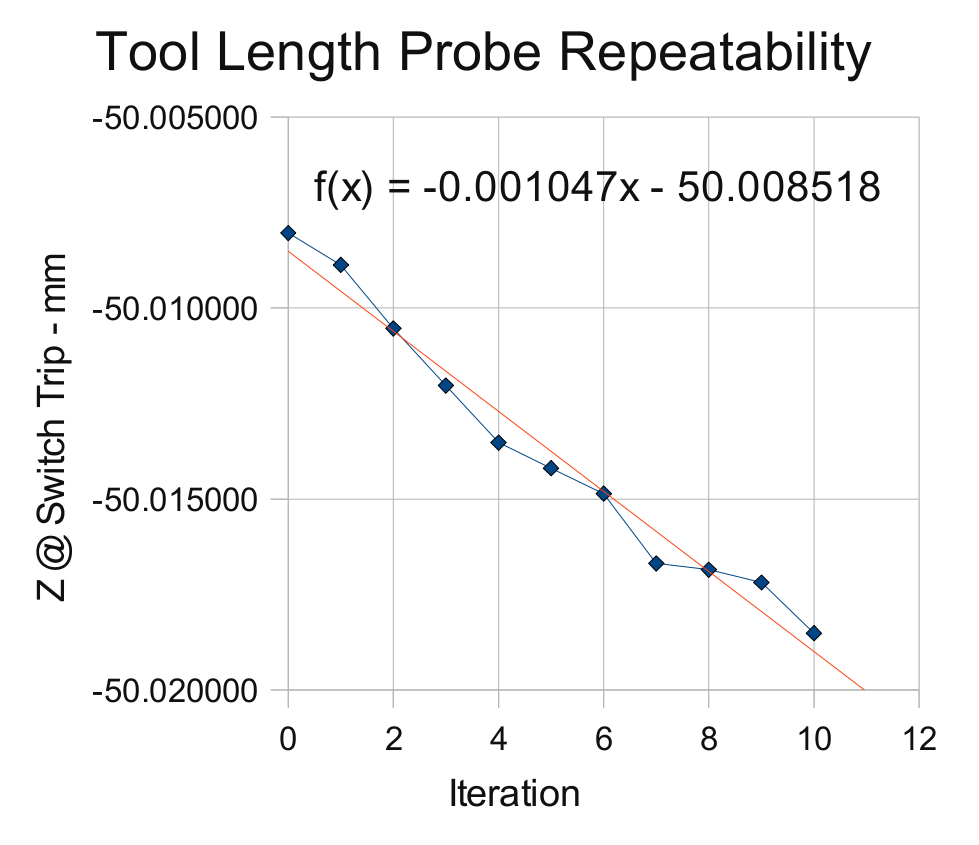
So I did that and here’s the result. The second column is the indicator reading in mils, with negative numbers being further down toward the tooling plate. The third column is the Z-axis coordinate of the probe switch trip in mm.
Iteration
Z @ Origin (mils)
Tool Z @ Probe (mm)
0
0.0
-50.008042
1
0.0
-50.008873
2
0.0
-50.010536
3
0.0
-50.012032
4
-0.1
-50.013526
5
0.0
-50.014193
6
-0.2
-50.014857
7
-0.1
-50.016686
8
-0.1
-50.016852
9
-0.1
-50.017185
10
-0.1
-50.018514
Probe drift
-0.010472
Now, that just cries out for a graph, doesn’t it?
Probe Switch Repeatability
The slope of the regression line says the switch is tripping about one wavelength of infrared light (1 micron) further down at each probe. Well, now, that’s not too bad, is it?
After ten probes, it’s descended about 10 microns, call it 0.3 mils, which is somewhat more than what the dial test indicator reports: 0.1 mil or just slightly more than the width of the indicator’s needle away from the 0.0 line.
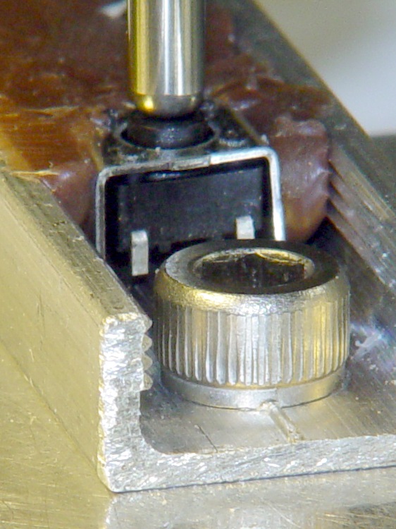
It turns out that the switch doesn’t have any mechanical overtravel whatsoever, so when the switch contacts close, the button is already pretty much bottomed out.
Switch ReleasedSwitch Over-pushed
The left picture shows the tool a few millimeters over the switch. Notice that the top of the black plastic switch body is snug against the metal frame. Although you can’t see it here, there’s nothing but air below the body; the brown hot-melt glue secures the sides and submerges the terminals & wiring.
The right pictures shows the situation after probing the switch at 300 mm/min. The switch body is pushed slightly downward from the metal shell, showing that the Z axis drive didn’t screech to an instant halt after the switch tripped.
My back of the envelope said it’d stop in about 7 mils from 12 in/min (call it 0.2 mm from 300 mm/min, which is what I actually used here). Turns out it’s more like 15 mils, about 0.4 mm. So much for the back of the envelope…
On the other hand, what’s a binary order of magnitude among friends?
The routines below do an initial probe at 300 mm/min, back off about 1 mm, then probe again at 10 mm/min. The theory was that the switch overtravel would soak up the initial probe and the second, more gentle, probe would always trip at the same Z-axis level.
Another good theory all shot to hell…
I should do the initial probe at, say, 100 mm/min and (to speed things up) put the tool change location as close to the switch as the longest tool will allow. That should cut the overtravel down to 5 mils, which ought not be a real problem.
However, I think the switch is usable as-is. It’s certainly more accurate than my manual tool height adjustment and I really don’t do many jobs that require more than a few tool changes, separated by long periods of chewing away at the part.
I suspect the switch gradually oozes back to its original position after being rudely poked, but I ought to check that, too.
The G-Code to make the tests happen:
(Tool length probing test)

(--------------------)
( Initialize first tool length at probe switch)
( assumes metric units!)

O<Probe_Init> SUB

G49					( clear tool length compensation)
G30					( to probe switch)
G91					( relative mode for probing)

G38.2 Z-90 F300		( trip switch on the way down)

G0 Z1				( back off the switch)
G38.2 Z-10 F10		( trip switch slowly)

#<_ToolRefZ> = #5063	( save trip point)

G90					( absolute mode)
G30					( return to safe level)

O<Probe_Init> ENDSUB

(--------------------)
( Initialize new tool length at probe switch)
( assumes metric units!)

O<Probe_Tool> SUB

G49					( clear tool length compensation)
G30					( to probe switch)
G91					( relative mode for probing)

G38.2 Z-90 F300		( trip switch on the way down)

G0 Z1				( back off the switch)
G38.2 Z-10 F10		( trip switch slowly)

#<_ToolZ> = #5063				( save new tool length)

G43.1 K[#<_ToolZ> - #<_ToolRefZ>]	( set new length)

G90					( absolute mode)
G30					( return to safe level)

O<Probe_Tool> ENDSUB

(--------------------)
( Set up first tool)

G21					( metric units)

(msg,Verify origin at indicator ball, hit Resume)
M0
(msg,Verify G30.1 above tool change switch, hit Resume)
M0
(msg,Verify blunt tool installed, hit Resume)
M0

O<Probe_Init> CALL

(debug,Initial tool length = #<_ToolRefZ>)

O100 REPEAT [10]

G0 X0 Y0
G0 Z0
(msg,Record indicator Z-axis reading, hit Resume)
M0

G0 Z5				(get air)
G30					(to tool change position)

O<Probe_Tool> CALL
(debug,Tool length offset = #<_ToolZ>)

O100 ENDREPEAT

M2
And here you thought that switch was a total piece of crap, didn’t you?
I’ve seen all manner of exceedingly fancy and painstakingly constructed tool length switch stations, but it seems ordinary snap-action / tactile-feedback switches are repeatable enough for most purposes. I selected a switch from my stash with these qualifications:
physically small — fits on Sherline table
plastic button — avoid nicking the cutters
many more in the stash — not a special-order item
cheap – ’nuff said
A few snippets of heat stink shrink tubing later…
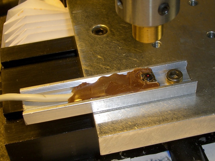
Switch detail
After puzzling over the mounting, I snagged a chunk of aluminum U-channel from the heap, poked a 10-32 clearance hole in one end, and held the switch in place while slobbering brown hot-melt glue over it. The glue is rigid when cool, so the switch isn’t going anywhere, but it’s mounted with some air space below to allow crushing when the probe routine screws up.
The button stands slightly proud of the U-channel, so even wide tools have side clearance. If the tool doesn’t stop when the switch trips (it could happen!), the entire switch will bend downward until the Z-axis drive stalls as the tool crushes the rubble or snags on the side of the U-channel.
At which point I just cut the cable, hammer the hot-melt glue and switch rubble out of the U-channel, solder up another switch, blob it in place, and continue the mission… from scratch, though, because the stored tool height reference value will be kaput.
The U-channel can be screwed down to a T-nut, clamped directly to the table, or affixed wherever it’s needed. If the Sherline had home switches, it’d be better to mount the probe switch in a fixed location somewhere, then use a fixture offset for the part, but I’m not there yet.
The switch doesn’t have much overtravel: when the contacts activate with a tactile click, the button is pretty much bottomed out. However, unless you’re driving the tool into the switch at a dead run, it ought to stop moving fairly quickly.
Back of the envelope: I have the Z axis acceleration set to (a sluggish) 3.0 in/s/s. Approaching the switch at 12 in/min = 0.2 in/s , it’ll screech to a halt in 67 ms = (0.2 in/s)/(3.0 in/s/s). Assuming the average velocity while stopping is 0.1 in/s, the distance works out to 7 mils, which shouldn’t pose a problem.
Then drive up off the switch enough to clear the backlash and drive down at nose-pickin’ speed, so the axis stops pretty much instantly when the switch clicks.
Some not-very-exhaustive testing suggests the repeatability for a single tool is well within 0.03 mm, about 0.001 inch, which is entirely satisfactory for my purposes.
[Update: It’s pretty good, all things considered. A simple experiment is there.]
The overall procedure:
Laser align XY to the part origin, home X&Y axes
Execute G49 to clear any existing tool length compensation
Insert first tool, align to Z=0 on part, home Z axis
Eyeball align XY to the switch with the tool just above
Jog Z comfortably high, execute G30.1 to set tool change location
Fire up your program!
The program probes the first tool length and saves that as the reference length. Each subsequent tool change gets probed and the tool offset becomes the difference between the new length and the reference length.
The initial probing routine:
O<Probe_Init> SUB

G49					( clear tool length compensation)
G30					( to probe switch)
G91					( relative mode for probing)

G38.2 Z-90 F300		( trip switch on the way down)
G0 Z1				( back off the switch)
G38.2 Z-10 F10		( trip switch slowly)

#<_ToolRefZ> = #5063	( save trip point)

G90					( absolute mode)
G30					( return to safe level)

O<Probe_Init> ENDSUB
Note that the G30 coordinates are stored in native units, which are inches for my Sherline mill. To get to that Z height (for safety, before moving) while using metric units:
G0 Z[#5183 * 25.4]
The G38.2 coordinates are stored in whatever units the G20/G21 mode calls for, so they can be applied directly to tool length compensation. That seems odd, as EMC assumes the tool table uses native units.
There does not seem to be any way to determine which unit mode is active, although the probe speed depends on that setting. although I suppose I could set a global variable to the desired probe speed and leave it up to the G-Code program(mer) to get it right. Yeah, like that’ll work…
Anyhow, each subsequent tool gets probed thusly:
O<Probe_Tool> SUB

G49					( clear tool length compensation)
G30					( to probe switch)
G91					( relative mode for probing)

G38.2 Z-90 F300		( trip switch on the way down)
G0 Z1				( back off the switch)
G38.2 Z-10 F10		( trip switch slowly)

#<_ToolZ> = #5063				( save new tool length)

G43.1 K[#<_ToolZ> - #<_ToolRefZ>]	( set new length)

G90					( absolute mode)
G30					( return to safe level)

O<Probe_Tool> ENDSUB
With those two routines in hand, this demo code shows how it’s done…
G21					( metric units)

(msg,Verify origin at proper location, hit Resume)
M0
(msg,Verify G30.1 at tool change switch, hit Resume)
M0
(msg,Verify first tool installed, hit Resume)
M0

O<Probe_Init> CALL

G0 X0 Y0 Z0
(msg,Verify return to origin, hit Resume)
M0

M6 T2
O<Probe_Tool> CALL

G0 X0 Y0 Z0
(msg,Verify return to origin, hit Resume)
M0

M6 T3
O<Probe_Tool> CALL

G0 X0 Y0 Z0
(msg,Verify return to origin, hit Resume)
M0

M6 T4
O<Probe_Tool> CALL

G0 X0 Y0 Z0
(msg,Verify return to origin...)
M2
The M6 Tx commands make use of a
TOOL_CHANGE_AT_G30 = 1
line in Sherline.ini, which tells the Axis automagic manual tool changer routine to traverse to the G30 position and pop up a prompt to (manually) change the tool. When you click OK, the subsequent CALL command invokes the tool length probe routine and away it goes.
This whole lashup doesn’t have a lot of power-on hours, but I really like how it works!
A tip o’ the cycling helmet to the folks behind EMC2…
I’ve been mulling over adding a tool length probe for a while and finally decided that the simplest approach might be the best: a momentary-contact pushbutton switch that pulls a parallel port input pin to ground.
The motivation is that a simple switch seems to be repeatable enough for tool length probing and it’s cheap enough that I won’t form a deep emotional bond to it. When a probe crashes the switch, I can just pop another one in place without any heartache or putzing around for a day or three to build another over-elaborate probe station.
The catch is that the Sherline motor driver box doesn’t include connections for any of the parallel port input pins.
The choices seem to boil down to:
Adding a breakout board between the parallel port and the driver box or
Hacking the driver box to get access to the port pins
Well, I’ve already pretty well hacked up my controller, as I wrote up in Circuit Cellar magazine (Aug & Oct 2004), so I don’t have much to lose… and the box is already in the shop!
Probe to port pin 15
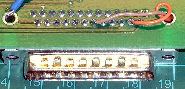
This picture shows the connection to pin 15 of the parallel port on the Sherline driver PCB. The driver doesn’t use that input pin (or any of the others, for that matter), which means the PCB doesn’t have a trace leading anywhere convenient. I ran the new wires through the connector mounting hole, rather than around the edge, and soldered them directly to the connector pins on the bottom of the board.
The jack is an ordinary 1/8″ (3.5 mm, these days) stereo (3 conductor) jack, with lah-dee-dah gratuitous gold-flavored flashed plating; anything similar will work just fine.
Connections:
Sleeve -> driver box
Ring -> circuit ground (pin 19 is convenient)
Tip -> pin 15, the probe input
The cable shield connects only at the plug into the driver box, not at the switch end. That ensures there’s no current flowing through it and it can do a marginally better job of shielding the two conductors within. I’m reasonably sure that makes no difference whatsoever in this application.
The cable got chopped out of an AV-interconnect dingus with all sorts of fancy connectors on the other end. It’s a surplus find, cost maybe a buck, and has the redeeming feature of sporting molded plugs that I don’t have to solder.
The switch connections are soldered and insulated with heat stink shrink tubing. The general idea is that the driver box provides all the power, there’s no electrical contact with the mill table or spindle, and thus no reason to use fancy circuitry to solve a problem that’s not there.
I did not add a capacitor across the switch contacts, figuring that I’d solve that problem when it happened. The common practice of putting a honkin’ big cap across switch contacts is bad practice: it effectively shorts the power supply across the contacts for a brief moment every time the switch closes. Some stored energy is good (it keeps the contacts clean), too much simply burns them away. ‘Nuff said.
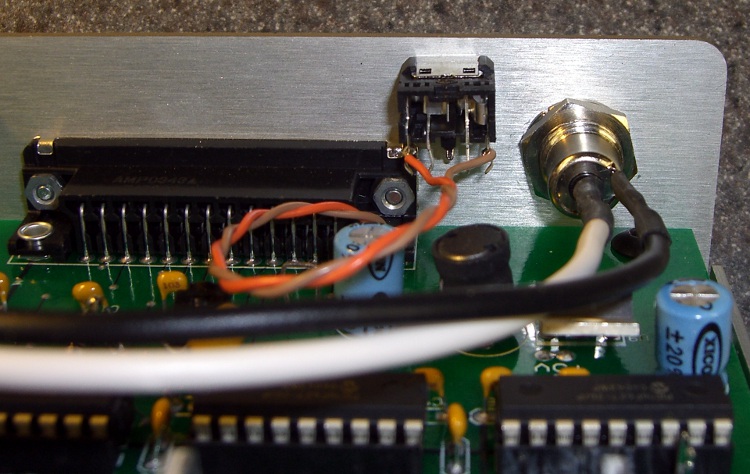
Probe jack – inside
I marked a hole on the front panel symmetric with the LED, eased the circuit board out of the case and wrapped it in a shop rag to keep the swarf out, propped the case on the drill press table, and rammed a 1/4″ hole through the spot marked X with a step drill. Yeah, hand-held on the table, just like you’re never supposed to do.
The force is strong with me…
The (well, my) Sherline.hal file connects pin 15 to the probe sense input (maybe I defined that when I set things up; I don’t recall now), but it assumes the pin will be high when active. The parallel port pin has a built-in pullup resistor and a switch to ground makes it active when low. These two lines in my custom_postgui.hal file disconnect the high-active pin signal and connect the low-active pin signal.
unlinkp parport.0.pin-15-in
net probe-in parport.0.pin-15-in-not
You do it that way to avoid changing the Sherline.hal file, which will be overwritten if you ever run the automagic configuration program again.
If you’re doing this from scratch, just configure the whole thing using the configuration tool, it’ll set the HAL file properly and you won’t need any of that fiddling around.
Tweak the Sherline.ini file to add support for tool changing with the G30 command:
[EMCIO]
TOOL_CHANGE_AT_G30 = 1
Button everything up, then do a quick
G91 G38.2 Z-10 F10
and poke the button while the Z axis is in motion. The Z axis should stop instantly. If not, check your wiring.
Now, some Orc Engineering is in order: I need a low-budget fixture to put the switch in harm’s way.
I used a pair of blue LEDs for the colon in the Totally Featureless Clock. Each one has a brass tube to define the dot and a white plastic diffuser to eliminate hotspots.
Some rummaging in the brass cutoff assortment produced a pair of tubes with a 0.300 inch ID that closely matched the width of the LED segment bars. The catch is that I don’t have a core drill that spits out 0.300 inch slugs…
Milling the dots
So I taped a chunk of translucent acrylic to some plywood scrap and milled the dots. Helix milling on the lesser of a 4% slope or 1/5 of the cutter diameter, 15 inches/min, no cooling, maybe 1500 rpm.
The resulting disks were snug slip fits into the tubes, although I added a dot of cyanoacrylate to ensure they didn’t get any ideas about perpetrating an escape.
It took two disks to remove all the hotspots, which reduced the light intensity to the point where I had to increase the LED current, which really heated up the linear regulator driving the dots. Fooey! In retrospect, I think frosting the LED lens would eliminate the need for a second diffuser without decreasing the intensity much at all.
The code is available as an OpenOffice file there, too.
(Post milling)
(Ed Nisley KE4ZNU - Feb 2010)
(Origin = center of post at surface)
(Double-stick tape holding acrylic sheet to sacrificial plate)

(-- Dimensions)

#<_PostDia>	= 0.300				(post OD)
#<_PostRad>	= [#<_PostDia> / 2]

#<_Thickness>	= 0.120			(sheet thickness)

#<_MillDia>	= 0.250				(cutter diameter)
#<_MillSpeed>	= 15				(cutting speed)

#<_MaxCutDepth>	= [#<_MillDia> / 5]	(max cutting depth)
#<_MaxCutSlope>	= 0.04			(max cutting slope)

#<_TraverseZ>	= 0.300				(safe travel height)
#<_TraverseSpeed> = 25			(safe traverse speed)

G20					(inches!)

(-- Figure cut depth per helix pass)

#<_PassCut> = [#<_MaxCutSlope> * 3.142 * [#<_PostDia> + #<_MillDia>]]		(limit max cut for each pass)

O9000 IF [#<_PassCut> GT #<_MaxCutDepth>]
#<_PassCut> = #<_MaxCutDepth>		(limit max cut for each pass)
O9000 ENDIF

(-- Set up cutter comp)

G0 Z#<_TraverseZ>

G0 X[0 - 3 * #<_PostRad>] Y0		(get to entry point)

G42.1 D#<_MillDia>
G2 X[0 - #<_PostRad>] I#<_PostRad> F#<_TraverseSpeed>

(-- cut down through sheet)

#<CurrentZ> = 0.0

G0 Z#<CurrentZ>

F#<_MillSpeed>

O1000 DO

#<NextZ> = [#<CurrentZ> - #<_PassCut>]	(figure ending level)

G3 I#<_PostRad> Z#<NextZ>		(once around)

#<CurrentZ> = #<NextZ>

O1000 WHILE [#<CurrentZ> GT [0 - #<_Thickness>]]

G3 I#<_PostRad>					(clear final ramp)

G40			(comp off)

G0 Z#<_TraverseZ>
G0 X0 Y0

M2
I finally made a test bar to line up the (vertically mounted) rotary table and tailstock on the Sherline milling machine. It’s a ground-and-polished 0.500-inch rod from a defunct HP2000C inkjet printer; the print head zipped back and forth along the rod while printing, so you know it’s pretty smooth. You could probably salvage something similar from any dead inkjet printer.
Making the bar is simple: saw off a suitable length, stick it in the lathe, face off the end, chamfer the edge, poke a center drill into it, and it’s all good.
If you’re a tool-and-die jig-boring high-precision kind of machinist, you better stop reading right about now before you catch a heart attack.
Lining the bar up is almost trivially easy with a laser spot coming down the spindle bore. Move the table so the spot grazes the side of the bar and casts a shadow on the table, jog X to the other end of the bar, and tweak the angle for the same picture on the table.
Repeat until satisfied.
The trouble comes at the tailstock end, where the ram extends about 1.5 inches, tops. That’s good enough for the Sherline, but it also means the test bar must be pretty close to the length of whatever you’ll be machining, rather than as long as possible to get the best alignment.
However, after you get Sherline tailstock aligned to the end of the bar, vertically, horizontally, and angularly, the magic happens
The ram is quite stable, with very little radial play, so the point moves along the X axis (assuming you did a good job aligning the tailstock). Retract the ram a bit, jog X and Y to put the laser spot on the tip of the center (which should correspond to the Y axis coordinate of the center of the bar), and you’ll see a defocused spot on the table (I put a white card on the table to improve the contrast). Jog Z until there’s a nice triangular image of the dead center’s point in that bright round spot.
It turns out that the laser beam in the top picture is about 10 mils wide at the dead center axis, so you can easily see a difference of 1 mil in the Y coordinate. That’s perfectly accurate for the sort of work I do.
Now, remove the test bar, unclamp the tailstock, move it to wherever you need it for the actual thing-to-be-made, snug it down, and jog the table in X (only!) to move the spot over there, too. Move the tailstock around to align the image of the center point in the middle of the laser spot again and you can be sure it’s aligned to the same Y coordinate. Verify that the tailstock has the same angular alignment. Mine is consistent with the T-nuts pressed against the front of the table slots and it’s easy to slide it carefully along the Y axis to get the point in the spot.
Because the bar was parallel to the X axis to start with, the point is now aligned with the axis of the rotary table.
Laser spot focused on tip
The minimum spot size depends on the beam width and the lens, but it turns out that for my setup, twiddling the Z position of the lens can shrink the spot down to essentially the width of the dead center point. As nearly as I can tell, the beam width is 3 mils and the point pretty much occludes the beam when it’s properly aligned.
The picture shows that situation; the spot is half-occluded because the point now looks like the side of a barn. It’s difficult to tell, but the lens (on the brass snout in the endmill holder) is lower in this picture.
All that jogging, particularly creeping up on the proper alignment, goes much easier with a joggy thing!